date-created: 2024-06-30 09:15:30 date-modified: 2024-10-09 06:52:04
Index
tags: #Social #Website
Overview
Hi, I’m Evelyn a cs-student at the university of tuebingen in Germany.
I “built” this website to gather experience with git-hooks, experience with mdbook and its features to parse md-files to html, well and to provide a space for:
- my ideas
- thoughts
- projects
- scripts and documentations
- maybe some scripts.
Goal and motivation:
Besides the reasons given above I generally wanted to share different thoughts and findings / experiences on some platform that are not dependant on another platform - i.e. social media or discord. Hence I’ve always thought of creating a webpage where I could give those things a foundation to rest on yet my first webpage was not updated often and I dropped the idea - primarily because I had no CMS running and it was entirely hardcoded, meaning I had to connect to the server whenever I wanted to change an information or write new entries - well and consider that i would have to update internal links, references and more, its a pain without any dedicated CMS running!
For some years - since 2022 I think - I’ve been logging, collecting and organizing my material, education and more via Obsidian and grew accustomed to the idea of writing everything down in markdown. With that idea in mind my optimal solution would’ve been a structure where I could write down things in Obsidian and then copy and link them to a repo which I could then update and push to some repo that would build a website out of it. At first I was thinking of doing that myself and thought this to be a good chance to work and experience Rust a little more, however I conceptualized a lot but had no to time to actually begin writing this all. While tutoring software engineering - 2023 - we began posting the script for our lecture via mdbook and that made me think whether I could make use of this infrastructure to finally deploy a website without much effort at all.
I describe the whole concept and idea of this blog in another post - here 452.07_own_webpage and 452.10_obsidian_vault_to_mdbook
and likely some more which I’m not listening or forgot about.
Some Quotes I like:
“We are perpetually trapped in a never ending spiral of life and death”.
Tormented by the fear of not being necessary
The intimate desire of acceptance
Overwhelmed by the fear of being alone
Documentation is a love letter that you write to your future self
Links | contact:
In case you would like to contact me I provide the following option(s):
-> mail: social.scattereddrifter@proton.me
where you might find me too:
date-created: 2024-04-08 12:22:10 date-modified: 2024-05-19 01:14:00
3d-Printing Filament
anchored to [[410.00_anchor|410.00_anchor]]
Introduction:
Theres different filament available that comes with different traits. I list those here in case they might be:
- good manufacturers
- interesting material
- interesting colours
- have interesting properties
PLA
- Sunlu CF PLA link
- Polytera matte PLA
- ESUN PLA
- Prusament
ABS
- ESUN ABS
- Sparta ABS or the german equivalent alchemy3d
Filament Clog | How to resolve them
anchored to 410.00_anchor
Overview
Whenever speaking about a filament clog the following scenarios are meant:
- something is obstructing the path from extruder to nozzle (mostly within the hotend to the nozzle) like metal parts, old filament or something else
- the heatbreak was clogged because the filament could heat up enough to melt the filament before reaching the hot-end thus being stuck. The latter is usually caused by retractions -> whenever the system is quickly pulling filament to prevent oozing / stringing. Because the heatbreak might be hot enough to soften/melt the plastic outside the heating-area (hotend) this retraction could then create a blob of filament stuck within the heat-break. Once this was caused one will not be able to print.
Fixes:
there are some tips / tricks that could help to resolve a clog within the heatbreak/hotend:
-
Using something (paperclip or drill bit etc.) to heat and poke through the assembly Heating up the component to use will allow to melt the plastic that is obscuring the path. Denote that it should be smaller than 1.7mm in diameter to fit through.
-
Heating up the heatbreak+heatsink to soften the filament link
Simply: Remove fan for the heatsink, heat up the hotend/heatbreak until it reaches a temperature where the plastic should soften/melt. Then poke it through with filament or something fitting through the tube.
This method is taken from the given post:
I have had PLA jamming in the heat break for various reasons. I am using a simple method to clear the heat break. I am sharing the method with you all. I’d love to get some thoughts on the safety of this method, possible drawbacks, pitfalls, etc.
My objective is to clear the heat break with the least possible disassembly. I did not want to remove the heat sink, nozzle, hotend, etc.
As a first step, I unscrew the heat sink fan and move it away. I also move away the cooling fan and the PINDA probe. Next, the extruder cover is removed. This completely exposes the heat sink portion. I move things away to make sure that all the sensitive items are as far away from the heat as possible. At this point, things look like this :
Remove the extruder idler screws. At this point I push a length of filament as far as possible through the PTFE tube, take it out, and reconfirm that the block is in the heat break.
By careful measurement, it should be possible to figure out exactly how much filament is stuck inside. Note that the E3D design is freely available - engineering drawings with dimensions are at http://wiki.e3d-online.com/wiki/E3D-v6_Documentation . I haven’t done this exercise, however.
Next, heat the nozzle to 210 degrees. Place a little book or piece of cardboard over the heat bed. If anything hot falls down, this will ensure that the heat bed is not impacted.
Wait a couple of minutes. Regularly keep sensing the temperature of the heat sink. Exercise care to ensure I don’t burn up any fingers. Once think the heat sink is hot enough, try pushing the filament in, through the PTFE tube. Note that the whole heatsink does not need to be hot - only the bottom portion closer to the heat break. That’s where the filament is stuck.
In a few minutes (2-4 minutes maximum - I did not time it), I am able to push the filament down with minimal effort and do some manual extrusion.
I now pull out the filament in quick motion. I issue a “Preheat | Cool down” command. The heat sink is in contact with ABS all the while, so ensure that you don’t keep it hot for any longer than absolutely required. You certainly don’t want the ABS to melt !
After everything cools down, push a filament through the PTFE tube as far as possible, check that the length that you are able to push in is much more than earlier - and something that looks enough to reach the heater block.
If you reached here, congratulations! Your heat break is clear. Put back everything back as it was earlier. Move the Z axis as far up as possible. Issue a Z calibration & check everything is still in order.
Preventing:
- printing with hotter temperatures
- reducing retraction (for all-steel heatbreaks - made for ABS - its recommend to stay below 0.4mm)
- install better fan to increase cooling capabilities for the heatsink
Issues with CANable - General Discussion - Klipper
anchored to [[410.00_anchor|410.00_anchor]] source: klipper.discourse.group read - estimated by firefox: 59–74 minutes
Hi,
I can’t post all the links as new user, so I put them all here: Kit: https://www.3dptronics.com/electronics/56-621-voron-24-complete-ptfe-wiring - Pastebin.com 18. I will refer to them in the body of this post. Sorry for the inconvenience.
I have Voron V2.4 350x350 with recent Canbus (EBB36) upgrade, using CANable adapter (1st link). Raspberry Pi 3B+ (32 bit kernel) and Octopus board. Upon install and setup, I had issues of random error “Lost communication with MCU ‘can0’” while printing. Following this post (2nd link), I found out that it is not hardware/wiring issue, but firmware issue, because ip -details -statistics link show can0 reports no dropped bytes, but mcu can0 interface statistics on Mainsail reported lots of bytes_invalid and bytes_retransmit.
I followed the advice in that post, and flashed updated firmware(3rd link) to CANable via dfu-utils. This got rid of the bytes_invalid and bytes_retransmit (both stayed at 0 even when testing).
However, my printer still randomly shuts down during bed mesh sometimes with the same “Lost communication with MCU ‘can0’” error. Klippy.log ends with Got error -1 in can write: (11)Resource temporarily unavailable'. If I run sudo dmesg, I get several Under-voltage detected! (0x00050005) errors. However, if I run vcgencmd measure_volts core (as well as sdram_c, sdram_i, sdram_p), I get completely nominal voltages.
Here are a few screenshots: (4th link)
My klippy.log: (5th link)
I am pretty sure there should be no actual undervolt, because everything was working fine before I added CANBUS to my printer setup. Can anyone help me figure this out?
How are you powering the rpi?
Undervoltage is to be taken seriously.
I am powering it via the 5V PSU on the Voron

That PSU is supplying 5.1V. Rpi is receiving 5.1V as well (I measured at both ends).
P.S. I added an extra 5V and GND wires from the PSU to the other pins on the Rpi, just to add some redundancy in case something is shaking loose, although connections look really strong and crimping is good.
It’s probably not your problem but you should never have multiple power/ground wires in parallel as you can get induced voltages with the ground/Vcc loops that you have added to the system.
A better place to look is how you made up your CAN bus wiring. How was that implemented?
Thank you for your reply. I had this whole issue even before I added these additional wires to Rpi. I can remove one pair and leave only one pair of really thick wires. However, when I added these additional wires yesterday, I stopped getting undervoltage warnings. Bed meshes seemed to work, so I thought maybe the issue is fixed, and tried another long print - and got a new error message some 4 hours into the print:
(Also attaching my Klippy.log, I trimmed the middle. But it really doesn’t show anything relevant that I can see).
Sudo dmesg shows this:
Some kind of “power save enabled” that I have never seen before. Not sure if this is relevant or not. This might have happened some time after the print failed, because I left it overnight and found it dead in the morning.
To answer your question about wiring, I am using the pre-crimped wires supplied with that kit I linked to. 4 wires in total. They are crimped onto a 4 pin connector, and connected to the EBB36. I am using several zip ties and strain relief gland to make absolutely sure the connector cannot move in any way when the toolhead moves. That part is rock solid. The wires then go through the umbilical sleeve into the electronics bay. CAN_LOW and CAN_HIGH are connected to the terminals of CANable and screwed down tight. 12V wire goes to the 12V PSU output, and GND goes to 12V PSU ground. Another wire goes from the third CANable to terminal also to the 12V PSU ground. CANable is connected to Rpi using a high quality 30cm USB cable. Let me know if this is what you wanted to know.
Thank you for your reply. I had this whole issue even before I added these additional wires to Rpi. I can remove one pair and leave only one pair of really thick wires. However, when I added these additional wires yesterday, I stopped getting undervoltage warnings. Bed meshes seemed to work, so I thought maybe the issue is fixed, and tried another long print - and got a new error message some 4 hours into the print:
I can’t attach my Klippy.log because of the damn forum restrictions, I will post it in separate reply.
Sudo dmesg shows this:
Some kind of “power save enabled” that I have never seen before. Not sure if this is relevant or not. This might have happened some time after the print failed, because I left it overnight and found it dead in the morning.
To answer your question about wiring, I am using the pre-crimped wires supplied with that kit I linked to. 4 wires in total. They are crimped onto a 4 pin connector, and connected to the EBB36. I am using several zip ties and strain relief gland to make absolutely sure the connector cannot move in any way when the toolhead moves. That part is rock solid. The wires then go through the umbilical sleeve into the electronics bay. CAN_LOW and CAN_HIGH are connected to the terminals of CANable and screwed down tight. 12V wire goes to the 12V PSU output, and GND goes to 12V PSU ground. Another wire goes from the third CANable to terminal also to the 12V PSU ground. CANable is connected to Rpi using a high quality 30cm USB cable. Let me know if this is what you wanted to know.
P.S. Before this new error happened last night, I also added a jumper on the “120R” pin on the EBB36, because I found some info that it helped some people. Apparently it didn’t help in this case.
On one of my printers I got the “Power Save Enabled” warning when I was powering my Raspberry Pi from a Mac that was nearby (I didn’t have a 5V AC/DC hooked up at the time). I replaced the PC/Mac connection with a Raspberry Pi wall wart and the issue went away.
When you say “one pair of really thick wires”, what do you mean? For my current connection, I’m using 16 AWG connected to a 5A AC/DC bulk supply soldered into a USB C prototyping connector for powering the rPi:

For a straight Raspberry Pi that isn’t powering anything, this would be overkill but in this printer the rPi is mounted to a BTT PITFT5.0 touch panel. When I measure the current on my bench supply in this configuration, it’s about 3.2A and 16 AWG is appropriate.
If you have a Raspberry Pi with no display mounted to it, the maximum current draw I’ve observed (with the rPi not powering any external devices) is 1.4A so you’ll want to use something like 20 AWG or 22 AWG to make sure your power cable losses are minimal.
I’m going through this level of detail because when I look at the schematics for the various CANable versions (1.0, 2.0 and Pro) it’s MCU is being powered by the Raspberry Pi. I’m guessing (based on the datasheet) that the CANable is drawing 200mA or so.
Now, you say that you are using an Octopus board, did you pull the USB Power jumper? If you don’t, the rPi will be providing 5V power for the entire board even when there is a bulk supply - expect the Octopus to draw at least an Amp with the stepper driver modules installed.

So, my big question is; what do you have attached to your Raspberry Pi’s USB and what is the current rating for the bulk 5V AC/DC that you are using? If you are powering the Octopus, CANable then the total 5V current draw is going to approach 3A. If you’re also powering a display like the BTT PITFT5.0 that I’m using then total rPi current draw will be north of 5A and, depending on your bulk supply and wire AWG size, you’ll see some voltage dips and the “Power Save Enabled” warning.
If you do have the Octopus’ USB power jumper in, pull it and see if this fixes the problem.
If all you have is the CANable and the EBB36 then you should have the jumpers enabling the 120 Ohm terminating resistors installed in both boards.
Good luck!
Thank you for your extensive reply. To answer your questions:
- I am using 18 AWG wires to power RPi (during yesterday’s experiment I even had two pairs of 18 AWG wires).
- The RPi is connected via USB only to the Octopus board (but the jumper you showed is not installed, so the Octopus board must be getting it’s power from the larger 24V PSU (Mean Well LRS-200-24)), and the CANable adapter - I’m pretty sure RPi is powering that one, because CANable doesn’t have any power lines coming to it, only ground. So it must be getting it’s power via USB.
- My LCD is connected and powered from the Octopus board (so, also not related to the 5V PSU).
- The PSU I am using for RPi is Mean Well RS25-5 (rated at 5A). It is powering nothing else, just RPi.
- I had installed the 120 Ohm jumpers on both the CANable and the EBB36 when the last print failure happened. Sorry I forgot to mention it.
So, to sum up - 5V PSU is only powering RPi, and RPi is only powering CANable. RPi and PSU connected with 18 AWG wires, and the total load should be well below 5A. Octopus, EBB36, LCD and the rest are all powered from the 24V PSU.
So basically my current setup during the last print failure already matches what you suggested  What do I do now?
Have you put a voltmeter on the output of the Mean Well 5V supply? It has an adjustment, maybe it’s a bit low from the factory.
The only other thing that I can think of is that there is a problem with your rPi’s 5V wiring - could you share a picture of the wires and how they go into the Raspberry Pi? If things got better when you added a second set of wires, that sounds like there may be an issue with the basic wiring.
Other than those two things, I can’t think of anything else. The “under-voltage” detected warning is pretty specific to the power supply going into the Raspberry Pi.
I measured the voltage out of 5V PSU - it is actually 5.1V. I also measured voltage at RPi - it is the same, meaning there is no drop due to wiring. If I knew when the issue is going to occur, I could measure at that time… But I don’t know how to cause it to happen on purpose, and chances are, if there is any voltage drop, it is very sudden and difficult to notice.
Here are the pictures you asked for: Imgur: The magic of the Internet 6
Sorry for bad cable management - I am trying to work out the issue so I’m rearranging things a lot. As you can see I still have two 5V wires going from the PSU to RPi (the two adjacent 5V pins). As for ground, I tried one to 5V PSU, one to 24V PSU (since the ground is shared, it shouldn’t matter, but I still wanted to try).
Thing is, if you remember, after adding the second pair of wires, I don’t get low voltage error anymore - just that “power save enabled”. Maybe it’s the same thing, I don’t know.
In any case, are you absolutely sure that this power supply issue is what’s causing CANable to lose connection? I really don’t know what else to do here as far as power supply goes.
You have a ground connection from each of the 5V and the 24V power supplies going to the Raspberry Pi? There’s a good chance that’s your problem - at the very least you have a big ground loop and, most likely, you have ground shift between the two power supplies that’s effectively lowering the 5V applied to the rPi.
Disconnect the Raspberry Pi ground lines from both the 5V and 24V supplies and run a new one, the same size as your 5V power line, from the 5V supply’s “-V” pin to the rPi’s Gnd.
It also looks like the CANable has a ground line connected to the 24V supply - you might want to disconnect that as well (I’m not impressed by the quality of the CANable circuitry).
Let’s see if this fixes your problem.
My apologies - I wasn’t aware that there is such a thing as ground loop. I thought it’s always best to connect all the grounds. I will try what you suggested, but then I have a question: should I connect the grounds of 5V and 24V PSU together or keep them separate? Also, what about the ground of the EBB36 and CANable - should I connect their grounds to RPi or instead to the 5V PSU “-V”?
No, keep the 24V and 5V grounds separate to the different devices. They’ll actually be connected through the USB connection between the rPi and the Octopus.
Honestly, I wonder if your problem is due to the thin ground wires on the rPi - the one going back to the 5V supply can’t carry all the current being provided so some of it is being shunted to the 24V supply with problems ensuing.
I’m not sure about the CANable with the third screw terminal that connects to “Ground”. I think you might have to leave that unconnected.
Let me know how things work.
Perhaps, I won’t pretend I understand how this all works  But in any case, I have rigged up the wiring as you suggested: 5V PSU connected only to the RPi, CANable connected only to RPi (via USB) and to EBB via CAN_HIGH and CAN_LOW, EBB only to 24V PSU. No ground shared between 5V and 24V PSUs, except through the USB cable between RPi and Octopus. Printer boots up so far, I will attempt a previously failed print (without filament) overnight. If anything I listed here is wrong, let me know. Otherwise, I will report the results tomorrow.
Okay, apparently we won’t have to wait. My printer halted during QGL, with the same error “Lost communication with MCU ‘can0’”. Klippy log shows nothing of interest at the end. “Sudo dmesg” shows “power save enabled” again. So basically everything the same as before, so I’m skipping screenshots.
I am at a complete loss. Like I wrote, RPi 5V and GND are connected to +5V and -5V on the PSU. No ground loops this time. Nothing else connected to these lines. The only other connections are via USB to CANable and Octopus.
EDIT: It seems that whatever we did, made things worse. I now get printer shutdown every time I try to QGL. Can’t even make a single one succeed. Klipper log now ends with b'Got error -1 in can write: (11)Resource temporarily unavailable'. Firmware restart doesn’t work, I am forced to use on/off switch to restart the printer.
I know it’s of little consolation but a consistent error like this is generally easier to find than an intermittent one.
Can you:
- Share your klippy.log
- Draw out your wiring? I feel like we’re missing something here.
Thanx.
Yeah, you are right. It’s always better when the issue is reproducible. Attaching my klippy.log after the last shutdown during QGL.
klippy(9).log (1.2 MB)
I have drawn out the wiring. Very crudely so, sorry for that. But it is accurate:

P.S. If you check my Klippy.log, something really interesting is happening at around line 8152 and onwards.
Power schematic looks good -that’s what I would expect. Based on what I’m seeing in the klippy(9).log and it not having any Under-voltage detected errors, I would say that the cleaned up wiring has fixed that problem.
Now, when I go through your klippy.log your Quad Gantry Level execution looks messed up. You have a metric shit tonne of macros in your printer.cfg and I can’t begin to follow them but it looks like you’ve set some really aggressive movements when you start the QGL (at line 8001). I guess you’re running with Klicky (based on the Probe “Dock” operation) and doing four probes for each point (based on what I’m seeing). I’m really not an expert at decoding klippy.log but I think you’re problem is being flagged at line 8127 with a Lost communication with MCU 'can0'.
Did you write all these macros or did you pick them up somewhere? Have they ever worked (with the CAN Bus) before?
Yes, I would expect the undervoltage issue is gone too, but like I said, I still get the “power save enabled” message when running “sudo dmesg” after printer has halted.
I have the UnKlicky probe on the toolhead. Yes, there are a lot of macros, I picked them up from various places. For example, QGL macro came with default Klipper install I think. Klicky related macros came from Klicky guides. Nozzle cleaning macro came from the wire brush guide. There are some macros for controlling LEDs and for sounds. I wrote a few maintenance macros myself, like bringing toolhead to various positions, etc.
Basically when I start new print, this is the sequence:
- Set bed temperature to target, heat soak for 5 minutes (I print PLA, so it is enough most of the time)
- Home all
- QGL
- Home Z
- Bed mesh
- Heat nozzle to 180°C
- Clean nozzle on the brush
- Auto-calibrate Z offset
- Heat nozzle to target temp
- Clean nozzle on the brush
- Move tool head to the center of the bed
To answer your question, yes, this setup worked really well for me. It worked without any issues before I installed CANBUS, and after installing it, sequence still works without issues on the occasions when I don’t get lost connection with mcu can0. So I don’t think this sequence is what triggers the lost connection, especially because like I said, if printer does get through this sequence, I still get print terminations several hours into the print.
Attaching my whole config directory if you want to take a look. I admit I could tidy it up a bit, so sorry for the mess!
2023 04 23.zip (34.2 KB)
Thank you, I will attempt this. For clarity, am I supposed to run the dump utility right after the printer loses connection with can0? I tested this tool out with candump -t z -Ddex can0,#FFFFFFFF, and it just slowly prints memory contents to the terminal. Is it going to eventually write them to a file?
No, just start logging to the candump.log file. You will need this file to use parsecandump.py.
Here is an informative video https://www.youtube.com/watch?v=ef4akXEDKOQ 5 about candump. You may also find a lot here in the forum. Many people have some problems with CAN bus.
Okay, I got the dump, attaching it. How do I use that parsecandump.py? It requires more arguments than just the dump file, I can’t find any documentation on this tool.
candump-2023-04-23_153346.log (449.2 KB)
EDIT: It says it requires can ID and something called mcu.dict, but I have no idea where to get that.
You have a LOT of macros and if you “picked them up from various places” then I would be very surprised if you have any idea what’s going on with them and how they interact. When I tried reading your klippy.log, there are things that don’t make sense, like setting max_velocity to 500 (along with your acceleration/deceleration/square corner velocity/etc.) repeatedly before starting your QGL.
Could I suggest that you eliminate essentially all of them and start working through the operation of the printer to eliminate the chance there is a macro problem before assuming you have a CAN problem or any other problem?
I think I have a decent understanding of how they work, and I included them for a reason. But sure, I can do what you suggested. Can you tell me specifically what I should do? Because right now, I just boot up the printer, press Home All in the Mainsail interface, then run QGL - and bam, I get shutdown due to loss of connection with can. So basically I’m just running two commands, and none of these macros should be called. They are listed in the klippy.log, but they aren’t called I think. So let me know what I need to change for the testing and I’ll do it.
Based on your previous posts and what I see in the klippy.log and what you’ve shared you’re doing an awful lot more than just basically “just running two commands”. When I look at your klippy.log, there’s a lot of commands executing I don’t understand the purpose of and you’re not paying me enough to figure them out.
You want to know what I think you need to change for testing? In looking at the printer.cfg, I would say start by taking out/commenting out the following lines:
[include stealthburner_leds.cfg]
[include purge_macro.cfg]
[include tones.cfg]
[include movement_macros.cfg]
[include calibration_macros.cfg]
[include toolhead_btt_ebbcan_G0B1_v1.2.cfg]
Which is basically literally everything but the basic mainsail.cfg macros (virtual_sdcard, PAUSE, RESUME, etc.).
Next, in printer.cfg, remove/comment out everything after “# Macros” including [include klicky-probe.cfg] When I look at klicky-probe.cfg I see:
#Simple way to include all the various klicky macros and configurations
# the current home for this configuration is https://github.com/jlas1/Klicky-Probe, please check it
#[include ./klicky-specific.cfg] #place to put other configurations specific to your printer
[include ./klicky-variables.cfg] #Required
[include ./klicky-macros.cfg] #Required
[include ./klicky-bed-mesh-calibrate.cfg] #bed mesh, requires klipper configuration
#[include ./klicky-screws-tilt-calculate.cfg] #help adjust bed screws automatically
[include ./klicky-quad-gantry-level.cfg] #level 4 Z motors
#[include ./klicky-z-tilt-adjust.cfg] #level 2 or 3 Z motors
Which moves us into several more levels of macros. I should point out that several of these macros aren’t included in the .zip file you provided.
Then, when you’ve done that, put in the basic Klicky dock and undock functionality and start testing.
Sorry for being so brutal, but I want to throw up my hands when I see header comments like:
# This macro was provided by discord user Garrettwp to whom i give my thanks for sharing it with me.
# I have tweaked it a lot.
# They are based on the great Annex magprobe dockable probe macros "#Originally developed by Mental,
# modified for better use on K-series printers by RyanG and Trails", kudos to them.
# That macro as since evolved into a klipper plugin that currently is pending inclusion in klipper,
# more information here, https://github.com/Annex-Engineering/Quickdraw_Probe/tree/main/Klipper_Macros
# User richardjm revised the macro variables and added some functions
# User sporkus added led status notifications
It’s like the power set up; go back to being as basic as possible, draw out the process and start working from there.
I apologize for my lack of knowledge. I am very new at this, and I’m trying to learn as fast as I can. I appreciate your patience.
Okay, so I did what you told me - for now, I removed all includes except for mainsail.cfg and toolhead_btt_ebbcan_G0B1_v1.2.cfg. I commented out all macros from the printer.cfg. Didn’t even include Klicky macros yet. Left the bare minimum. After doing this, I cannot even make a full restart - Klipper gets stuck in Klipper reports: STARTUP blue screen for a while, and then throws mcu 'can0': Unable to connect again. Klippy.log keeps growing and is not resetting - meaning, at the beginning I still see logs from old tests, and the new log is just appended at the end of the file. Attaching for you to see.
klippy(14).log (2.2 MB) Not even turning printer power off and on back again fixes this. I am really confused.
I cleaned up printer.cfg as much as I could - removed all unnecessary comments, organized everything, moved in everything needed to boot up the printer except for mainsail.cfg (which is still included):
printer.cfg (9.0 KB)
And I still get the same issue, printer is not booting due to can0:
klippy(16).log (2.3 MB)
The log has one line that I didn’t notice before, or maybe it is new:
mcu 'can0': Unable to open CAN port: Failed to transmit: [Errno 105] No buffer space available
Researching this now, but just letting you know.
Okay, what I would recommend is going through the CAN set up procedure again following something like:
or this video which is highly rated/go to for Vorons:
Hopefully things will come together from doing that and you can start moving forwards again.
Okay, I went through the whole procedure again like you suggested, step by step, not missing anything. Still the same. Printer is not booting with the same error.
klippy(17).log (2.3 MB)
I guess there is no docu. I never used parsecandump.py. koconner stated “It works similarly to the existing klippy/parsedump.py tool”. I would look here in the documantation Debugging - Klipper documentation
Line 109 in parsecandump.py says: (sorry I can’t quote the original source, discourse shows not what I write). Just have a look at the original file https://github.com/Klipper3d/klipper/compare/work-parsecandump-20230417 1
usage = “%prog <candump.log> >canid> <mcu.dict>”
I would take can0 for >canid>, but for <mcu.dict> I have no clue. I guess it has something to do with debugging Klipper in batch mode.
What do you get when you do an ifconfig command in ssh?
You should be seeing something like this at the start of the response:
can0: flags=193<UP,RUNNING,NOARP> mtu 16
unspec 00-00-00-00-00-00-00-00-00-00-00-00-00-00-00-00 txqueuelen 256 (UNSPEC)
RX packets 1031046 bytes 7522103 (7.1 MiB)
RX errors 0 dropped 0 overruns 0 frame 0
TX packets 85056 bytes 566641 (553.3 KiB)
TX errors 0 dropped 0 overruns 0 carrier 0 collisions 0
Let’s first make sure can0 exists in your system.
Thanks, I figured it out, the python script referred to klipper.dict in the out directory. So I ran python parsecandump.py candump-2023-04-23_153346.log afac3c9694c2 ../out/klipper.dict and got this:

Sorry - the script doesn’t output it into a file, I don’t know how to do it, hence the screenshot.
It seems to exist. Here is what I get:
pi@V24RP:~/klipper/klippy $ ifconfig
can0: flags=193<UP,RUNNING,NOARP> mtu 16
unspec 00-00-00-00-00-00-00-00-00-00-00-00-00-00-00-00 txqueuelen 1000 (UNSPEC)
RX packets 55460831 bytes 443686648 (423.1 MiB)
RX errors 0 dropped 0 overruns 0 frame 0
TX packets 3 bytes 24 (24.0 B)
TX errors 0 dropped 0 overruns 0 carrier 0 collisions 0
eth0: flags=4099<UP,BROADCAST,MULTICAST> mtu 1500
ether b8:27:eb:12:1e:4d txqueuelen 1000 (Ethernet)
RX packets 0 bytes 0 (0.0 B)
RX errors 0 dropped 0 overruns 0 frame 0
TX packets 0 bytes 0 (0.0 B)
TX errors 0 dropped 0 overruns 0 carrier 0 collisions 0
lo: flags=73<UP,LOOPBACK,RUNNING> mtu 65536
inet 127.0.0.1 netmask 255.0.0.0
inet6 ::1 prefixlen 128 scopeid 0x10<host>
loop txqueuelen 1000 (Local Loopback)
RX packets 79067 bytes 29945480 (28.5 MiB)
RX errors 0 dropped 0 overruns 0 frame 0
TX packets 79067 bytes 29945480 (28.5 MiB)
TX errors 0 dropped 0 overruns 0 carrier 0 collisions 0
wlan0: flags=4163<UP,BROADCAST,RUNNING,MULTICAST> mtu 1500
inet 192.168.1.170 netmask 255.255.255.0 broadcast 192.168.1.255
inet6 fda3:85e6:18dd:0:11e4:10f0:29b4:5e2e prefixlen 64 scopeid 0x0<global>
inet6 fe80::9241:5f6b:371:8a94 prefixlen 64 scopeid 0x20<link>
inet6 fda3:85e6:18dd::2de prefixlen 128 scopeid 0x0<global>
ether b8:27:eb:47:4b:18 txqueuelen 1000 (Ethernet)
RX packets 57670 bytes 4416704 (4.2 MiB)
RX errors 0 dropped 0 overruns 0 frame 0
TX packets 70942 bytes 66710953 (63.6 MiB)
TX errors 0 dropped 0 overruns 0 carrier 0 collisions 0
cool, do us a favor and post all files you got zipped @https://pastebin.com/
 yes, that was also my feeling, klipper.dict! I never heard about mcu.dict.
Can you clarify what files you meant? This python script produces none, it only outputs everything to the console, but the console can’t handle that many lines, so I only get the last part of the parse. What do you want me to upload?
Please do the hole procedure again. Do what you what to do until you get your failure.
And than post every file you generated after using parsecandump.py. Just post everything.
Please post the contents of /etc/network/interfaces.d/can0.
It’s also not clear to me if the firmware you flashed on the CANable is meant for the MKS clone. I built candlelight firmware from source specifically for the MKS clone if you want to try it. I’ve been using the non-pro version of the MKS CANable for quite some time on my 2.4 with no issues. I run Huvuds on my A and B motors, and an SB2040 on the toolhead all running through the CANable at 1M.
CANable_MKS_fw.bin.zip (12.7 KB)
Contents of /etc/network/interfaces.d/can0 are:
auto can0
iface can0 can static
bitrate 5000000
up ifconfig $IFACE txqueuelen 1000
Previously I also tried:
allow-hotplug can0
ifface cam0 can static
bitrate 10000000
up ip link set can0 txqueuelen 1024
There seems to be no difference - I get the error with either one of them.
I now will try to flash that firmware you provided, than you.
Both of these have problems and won’t work. You’ve specified a bitrate in the top one of 5M which is not valid. You need to change it to 500000, and I would also suggest using a txqueuelen of 128 as recommended in the Klipper docs. Try using this:
auto can0
iface can0 can static
bitrate 500000
up ifconfig $IFACE txqueuelen 128
You also need to reboot after editing this file.
I should mention, I’m assuming you’ve flashed your EBB36 with firmware for 500k baud. If you flashed it for a different speed, you need to match that speed in your interfaces file. You can’t mix and match.
Thank you very much. I guess this was what I messed up. I flashed with 1M baud. So now I set my /etc/network/interfaces.d/can0 to:
auto can0
iface can0 can static
bitrate 1000000
up ifconfig $IFACE txqueuelen 128
And the printer finally boots. I will now attempt to bring in a minimum amount of macros to perform homing and QGL to see if the issue persists.
Okay, so after this change, printer boots, but it still crashes during QGL with Lost communication with MCU 'can0'
For clarity:
My /etc/network/interfaces.d/can0 is:
auto can0
iface can0 can static
bitrate 1000000
up ifconfig $IFACE txqueuelen 128
My printer.cfg is:
printer.cfg (9.1 KB)
(I included the minimum amount of Klicky configs/macro files to make it possible to perform QGL)
sudo dmesg reports:
pi@V24RP:~ $ sudo dmesg
[ 0.000000] Booting Linux on physical CPU 0x0
[ 0.000000] Linux version 5.10.103-v7+ (dom@buildbot) (arm-linux-gnueabihf-gcc-8 (Ubuntu/Linaro 8.4.0-3ubuntu1) 8.4.0, GNU ld (GNU Binutils for Ubuntu) 2.34) #1529 SMP Tue Mar 8 12:21:37 GMT 2022
[ 0.000000] CPU: ARMv7 Processor [410fd034] revision 4 (ARMv7), cr=10c5383d
[ 0.000000] CPU: div instructions available: patching division code
[ 0.000000] CPU: PIPT / VIPT nonaliasing data cache, VIPT aliasing instruction cache
[ 0.000000] OF: fdt: Machine model: Raspberry Pi 3 Model B Plus Rev 1.3
[ 0.000000] random: fast init done
[ 0.000000] Memory policy: Data cache writealloc
[ 0.000000] Reserved memory: created CMA memory pool at 0x34000000, size 64 MiB
[ 0.000000] OF: reserved mem: initialized node linux,cma, compatible id shared-dma-pool
[ 0.000000] Zone ranges:
[ 0.000000] DMA [mem 0x0000000000000000-0x0000000037ffffff]
[ 0.000000] Normal empty
[ 0.000000] Movable zone start for each node
[ 0.000000] Early memory node ranges
[ 0.000000] node 0: [mem 0x0000000000000000-0x0000000037ffffff]
[ 0.000000] Initmem setup node 0 [mem 0x0000000000000000-0x0000000037ffffff]
[ 0.000000] On node 0 totalpages: 229376
[ 0.000000] DMA zone: 2016 pages used for memmap
[ 0.000000] DMA zone: 0 pages reserved
[ 0.000000] DMA zone: 229376 pages, LIFO batch:63
[ 0.000000] percpu: Embedded 20 pages/cpu s50828 r8192 d22900 u81920
[ 0.000000] pcpu-alloc: s50828 r8192 d22900 u81920 alloc=20*4096
[ 0.000000] pcpu-alloc: [0] 0 [0] 1 [0] 2 [0] 3
[ 0.000000] Built 1 zonelists, mobility grouping on. Total pages: 227360
[ 0.000000] Kernel command line: coherent_pool=1M 8250.nr_uarts=1 snd_bcm2835.enable_compat_alsa=0 snd_bcm2835.enable_hdmi=1 bcm2708_fb.fbwidth=656 bcm2708_fb.fbheight=416 bcm2708_fb.fbswap=1 vc_mem.mem_base=0x3ec00000 vc_mem.mem_size=0x40000000 console=tty1 root=PARTUUID=b1d487b5-02 rootfstype=ext4 fsck.repair=yes rootwait
[ 0.000000] Dentry cache hash table entries: 131072 (order: 7, 524288 bytes, linear)
[ 0.000000] Inode-cache hash table entries: 65536 (order: 6, 262144 bytes, linear)
[ 0.000000] mem auto-init: stack:off, heap alloc:off, heap free:off
[ 0.000000] Memory: 826024K/917504K available (10240K kernel code, 1312K rwdata, 2952K rodata, 1024K init, 862K bss, 25944K reserved, 65536K cma-reserved)
[ 0.000000] SLUB: HWalign=64, Order=0-3, MinObjects=0, CPUs=4, Nodes=1
[ 0.000000] ftrace: allocating 32081 entries in 95 pages
[ 0.000000] ftrace: allocated 94 pages with 5 groups
[ 0.000000] rcu: Hierarchical RCU implementation.
[ 0.000000] Rude variant of Tasks RCU enabled.
[ 0.000000] Tracing variant of Tasks RCU enabled.
[ 0.000000] rcu: RCU calculated value of scheduler-enlistment delay is 10 jiffies.
[ 0.000000] NR_IRQS: 16, nr_irqs: 16, preallocated irqs: 16
[ 0.000000] random: get_random_bytes called from start_kernel+0x3ac/0x580 with crng_init=1
[ 0.000000] arch_timer: cp15 timer(s) running at 19.20MHz (phys).
[ 0.000000] clocksource: arch_sys_counter: mask: 0xffffffffffffff max_cycles: 0x46d987e47, max_idle_ns: 440795202767 ns
[ 0.000007] sched_clock: 56 bits at 19MHz, resolution 52ns, wraps every 4398046511078ns
[ 0.000024] Switching to timer-based delay loop, resolution 52ns
[ 0.000310] Console: colour dummy device 80x30
[ 0.001131] printk: console [tty1] enabled
[ 0.001204] Calibrating delay loop (skipped), value calculated using timer frequency.. 38.40 BogoMIPS (lpj=192000)
[ 0.001263] pid_max: default: 32768 minimum: 301
[ 0.001489] LSM: Security Framework initializing
[ 0.001753] Mount-cache hash table entries: 2048 (order: 1, 8192 bytes, linear)
[ 0.001802] Mountpoint-cache hash table entries: 2048 (order: 1, 8192 bytes, linear)
[ 0.003274] cgroup: Disabling memory control group subsystem
[ 0.003559] CPU: Testing write buffer coherency: ok
[ 0.004076] CPU0: thread -1, cpu 0, socket 0, mpidr 80000000
[ 0.005334] Setting up static identity map for 0x100000 - 0x10003c
[ 0.005543] rcu: Hierarchical SRCU implementation.
[ 0.006481] smp: Bringing up secondary CPUs ...
[ 0.007653] CPU1: thread -1, cpu 1, socket 0, mpidr 80000001
[ 0.008929] CPU2: thread -1, cpu 2, socket 0, mpidr 80000002
[ 0.010244] CPU3: thread -1, cpu 3, socket 0, mpidr 80000003
[ 0.010402] smp: Brought up 1 node, 4 CPUs
[ 0.010456] SMP: Total of 4 processors activated (153.60 BogoMIPS).
[ 0.010488] CPU: All CPU(s) started in HYP mode.
[ 0.010515] CPU: Virtualization extensions available.
[ 0.011520] devtmpfs: initialized
[ 0.029036] VFP support v0.3: implementor 41 architecture 3 part 40 variant 3 rev 4
[ 0.029332] clocksource: jiffies: mask: 0xffffffff max_cycles: 0xffffffff, max_idle_ns: 19112604462750000 ns
[ 0.029394] futex hash table entries: 1024 (order: 4, 65536 bytes, linear)
[ 0.032438] pinctrl core: initialized pinctrl subsystem
[ 0.033640] NET: Registered protocol family 16
[ 0.037856] DMA: preallocated 1024 KiB pool for atomic coherent allocations
[ 0.043600] audit: initializing netlink subsys (disabled)
[ 0.044514] thermal_sys: Registered thermal governor 'step_wise'
[ 0.045310] audit: type=2000 audit(0.040:1): state=initialized audit_enabled=0 res=1
[ 0.045537] hw-breakpoint: found 5 (+1 reserved) breakpoint and 4 watchpoint registers.
[ 0.045579] hw-breakpoint: maximum watchpoint size is 8 bytes.
[ 0.045901] Serial: AMBA PL011 UART driver
[ 0.065276] bcm2835-mbox 3f00b880.mailbox: mailbox enabled
[ 0.080151] raspberrypi-firmware soc:firmware: Attached to firmware from 2021-12-01T15:08:00, variant start_x
[ 0.090163] raspberrypi-firmware soc:firmware: Firmware hash is 71bd3109023a0c8575585ba87cbb374d2eeb038f
[ 0.134405] Kprobes globally optimized
[ 0.139425] bcm2835-dma 3f007000.dma: DMA legacy API manager, dmachans=0x1
[ 0.141802] SCSI subsystem initialized
[ 0.142088] usbcore: registered new interface driver usbfs
[ 0.142174] usbcore: registered new interface driver hub
[ 0.142267] usbcore: registered new device driver usb
[ 0.144203] clocksource: Switched to clocksource arch_sys_counter
[ 1.863374] VFS: Disk quotas dquot_6.6.0
[ 1.863527] VFS: Dquot-cache hash table entries: 1024 (order 0, 4096 bytes)
[ 1.863751] FS-Cache: Loaded
[ 1.864006] CacheFiles: Loaded
[ 1.873968] NET: Registered protocol family 2
[ 1.874317] IP idents hash table entries: 16384 (order: 5, 131072 bytes, linear)
[ 1.876414] tcp_listen_portaddr_hash hash table entries: 512 (order: 0, 6144 bytes, linear)
[ 1.876509] TCP established hash table entries: 8192 (order: 3, 32768 bytes, linear)
[ 1.876654] TCP bind hash table entries: 8192 (order: 4, 65536 bytes, linear)
[ 1.876867] TCP: Hash tables configured (established 8192 bind 8192)
[ 1.877072] UDP hash table entries: 512 (order: 2, 16384 bytes, linear)
[ 1.877151] UDP-Lite hash table entries: 512 (order: 2, 16384 bytes, linear)
[ 1.877456] NET: Registered protocol family 1
[ 1.878306] RPC: Registered named UNIX socket transport module.
[ 1.878341] RPC: Registered udp transport module.
[ 1.878370] RPC: Registered tcp transport module.
[ 1.878399] RPC: Registered tcp NFSv4.1 backchannel transport module.
[ 1.880069] hw perfevents: enabled with armv7_cortex_a7 PMU driver, 7 counters available
[ 1.883792] Initialise system trusted keyrings
[ 1.884080] workingset: timestamp_bits=14 max_order=18 bucket_order=4
[ 1.893697] zbud: loaded
[ 1.895846] FS-Cache: Netfs 'nfs' registered for caching
[ 1.896765] NFS: Registering the id_resolver key type
[ 1.896827] Key type id_resolver registered
[ 1.896857] Key type id_legacy registered
[ 1.897028] nfs4filelayout_init: NFSv4 File Layout Driver Registering...
[ 1.897065] nfs4flexfilelayout_init: NFSv4 Flexfile Layout Driver Registering...
[ 1.898297] Key type asymmetric registered
[ 1.898331] Asymmetric key parser 'x509' registered
[ 1.898403] Block layer SCSI generic (bsg) driver version 0.4 loaded (major 249)
[ 1.898443] io scheduler mq-deadline registered
[ 1.898473] io scheduler kyber registered
[ 1.902011] bcm2708_fb soc:fb: FB found 1 display(s)
[ 1.914701] Console: switching to colour frame buffer device 82x26
[ 1.922021] bcm2708_fb soc:fb: Registered framebuffer for display 0, size 656x416
[ 1.931116] Serial: 8250/16550 driver, 1 ports, IRQ sharing enabled
[ 1.936046] bcm2835-rng 3f104000.rng: hwrng registered
[ 1.939042] vc-mem: phys_addr:0x00000000 mem_base=0x3ec00000 mem_size:0x40000000(1024 MiB)
[ 1.945056] gpiomem-bcm2835 3f200000.gpiomem: Initialised: Registers at 0x3f200000
[ 1.962602] brd: module loaded
[ 1.977575] loop: module loaded
[ 1.982145] Loading iSCSI transport class v2.0-870.
[ 1.986802] usbcore: registered new interface driver lan78xx
[ 1.989525] usbcore: registered new interface driver smsc95xx
[ 1.992124] dwc_otg: version 3.00a 10-AUG-2012 (platform bus)
[ 2.723189] Core Release: 2.80a
[ 2.725758] Setting default values for core params
[ 2.728272] Finished setting default values for core params
[ 2.931149] Using Buffer DMA mode
[ 2.933673] Periodic Transfer Interrupt Enhancement - disabled
[ 2.936287] Multiprocessor Interrupt Enhancement - disabled
[ 2.938874] OTG VER PARAM: 0, OTG VER FLAG: 0
[ 2.941416] Dedicated Tx FIFOs mode
[ 2.944431] WARN::dwc_otg_hcd_init:1074: FIQ DMA bounce buffers: virt = b4114000 dma = 0xf4114000 len=9024
[ 2.951524] FIQ FSM acceleration enabled for :
Non-periodic Split Transactions
Periodic Split Transactions
High-Speed Isochronous Endpoints
Interrupt/Control Split Transaction hack enabled
[ 2.962491] dwc_otg: Microframe scheduler enabled
[ 2.962572] WARN::hcd_init_fiq:457: FIQ on core 1
[ 2.966892] WARN::hcd_init_fiq:458: FIQ ASM at 807cb8b8 length 36
[ 2.971322] WARN::hcd_init_fiq:497: MPHI regs_base at b8810000
[ 2.975773] dwc_otg 3f980000.usb: DWC OTG Controller
[ 2.978085] dwc_otg 3f980000.usb: new USB bus registered, assigned bus number 1
[ 2.980453] dwc_otg 3f980000.usb: irq 89, io mem 0x00000000
[ 2.982774] Init: Port Power? op_state=1
[ 2.985020] Init: Power Port (0)
[ 2.987542] usb usb1: New USB device found, idVendor=1d6b, idProduct=0002, bcdDevice= 5.10
[ 2.992130] usb usb1: New USB device strings: Mfr=3, Product=2, SerialNumber=1
[ 2.994611] usb usb1: Product: DWC OTG Controller
[ 2.996969] usb usb1: Manufacturer: Linux 5.10.103-v7+ dwc_otg_hcd
[ 2.999364] usb usb1: SerialNumber: 3f980000.usb
[ 3.002543] hub 1-0:1.0: USB hub found
[ 3.005026] hub 1-0:1.0: 1 port detected
[ 3.008849] dwc_otg: FIQ enabled
[ 3.008862] dwc_otg: NAK holdoff enabled
[ 3.008874] dwc_otg: FIQ split-transaction FSM enabled
[ 3.008892] Module dwc_common_port init
[ 3.009183] usbcore: registered new interface driver usb-storage
[ 3.011851] mousedev: PS/2 mouse device common for all mice
[ 3.015549] bcm2835-wdt bcm2835-wdt: Broadcom BCM2835 watchdog timer
[ 3.020736] sdhci: Secure Digital Host Controller Interface driver
[ 3.023275] sdhci: Copyright(c) Pierre Ossman
[ 3.026573] mmc-bcm2835 3f300000.mmcnr: could not get clk, deferring probe
[ 3.029819] sdhost-bcm2835 3f202000.mmc: could not get clk, deferring probe
[ 3.032639] sdhci-pltfm: SDHCI platform and OF driver helper
[ 3.037180] ledtrig-cpu: registered to indicate activity on CPUs
[ 3.040203] hid: raw HID events driver (C) Jiri Kosina
[ 3.042958] usbcore: registered new interface driver usbhid
[ 3.045600] usbhid: USB HID core driver
[ 3.053493] Initializing XFRM netlink socket
[ 3.056149] NET: Registered protocol family 17
[ 3.058767] Key type dns_resolver registered
[ 3.061732] Registering SWP/SWPB emulation handler
[ 3.064266] registered taskstats version 1
[ 3.066613] Loading compiled-in X.509 certificates
[ 3.069822] Key type ._fscrypt registered
[ 3.072147] Key type .fscrypt registered
[ 3.074505] Key type fscrypt-provisioning registered
[ 3.088018] uart-pl011 3f201000.serial: there is not valid maps for state default
[ 3.092879] uart-pl011 3f201000.serial: cts_event_workaround enabled
[ 3.095420] 3f201000.serial: ttyAMA0 at MMIO 0x3f201000 (irq = 114, base_baud = 0) is a PL011 rev2
[ 3.102649] bcm2835-power bcm2835-power: Broadcom BCM2835 power domains driver
[ 3.106958] mmc-bcm2835 3f300000.mmcnr: mmc_debug:0 mmc_debug2:0
[ 3.109484] mmc-bcm2835 3f300000.mmcnr: DMA channel allocated
[ 3.134353] Indeed it is in host mode hprt0 = 00021501
[ 3.198677] sdhost: log_buf @ (ptrval) (f4113000)
[ 3.239557] mmc1: queuing unknown CIS tuple 0x80 (2 bytes)
[ 3.243678] mmc1: queuing unknown CIS tuple 0x80 (3 bytes)
[ 3.247762] mmc1: queuing unknown CIS tuple 0x80 (3 bytes)
[ 3.251130] mmc0: sdhost-bcm2835 loaded - DMA enabled (>1)
[ 3.256441] of_cfs_init
[ 3.259010] of_cfs_init: OK
[ 3.262501] Waiting for root device PARTUUID=b1d487b5-02...
[ 3.275535] mmc1: queuing unknown CIS tuple 0x80 (7 bytes)
[ 3.342603] mmc0: host does not support reading read-only switch, assuming write-enable
[ 3.347499] usb 1-1: new high-speed USB device number 2 using dwc_otg
[ 3.350239] Indeed it is in host mode hprt0 = 00001101
[ 3.414448] mmc0: new high speed SDHC card at address aaaa
[ 3.417931] mmcblk0: mmc0:aaaa SD32G 29.7 GiB
[ 3.423519] mmc1: new high speed SDIO card at address 0001
[ 3.428482] mmcblk0: p1 p2
[ 3.454310] EXT4-fs (mmcblk0p2): INFO: recovery required on readonly filesystem
[ 3.456659] EXT4-fs (mmcblk0p2): write access will be enabled during recovery
[ 3.584653] usb 1-1: New USB device found, idVendor=0424, idProduct=2514, bcdDevice= b.b3
[ 3.589370] usb 1-1: New USB device strings: Mfr=0, Product=0, SerialNumber=0
[ 3.592729] hub 1-1:1.0: USB hub found
[ 3.595432] hub 1-1:1.0: 4 ports detected
[ 3.648351] EXT4-fs (mmcblk0p2): recovery complete
[ 3.653103] EXT4-fs (mmcblk0p2): mounted filesystem with ordered data mode. Opts: (null)
[ 3.658477] VFS: Mounted root (ext4 filesystem) readonly on device 179:2.
[ 3.669267] devtmpfs: mounted
[ 3.679548] Freeing unused kernel memory: 1024K
[ 3.682763] Run /sbin/init as init process
[ 3.685421] with arguments:
[ 3.685432] /sbin/init
[ 3.685443] with environment:
[ 3.685454] HOME=/
[ 3.685465] TERM=linux
[ 3.914269] usb 1-1.1: new high-speed USB device number 3 using dwc_otg
[ 4.044637] usb 1-1.1: New USB device found, idVendor=0424, idProduct=2514, bcdDevice= b.b3
[ 4.049986] usb 1-1.1: New USB device strings: Mfr=0, Product=0, SerialNumber=0
[ 4.053725] hub 1-1.1:1.0: USB hub found
[ 4.056689] hub 1-1.1:1.0: 3 ports detected
[ 4.154271] usb 1-1.2: new full-speed USB device number 4 using dwc_otg
[ 4.261393] systemd[1]: System time before build time, advancing clock.
[ 4.301277] usb 1-1.2: New USB device found, idVendor=1d50, idProduct=614e, bcdDevice= 1.00
[ 4.306772] usb 1-1.2: New USB device strings: Mfr=1, Product=2, SerialNumber=3
[ 4.309591] usb 1-1.2: Product: stm32f446xx
[ 4.312323] usb 1-1.2: Manufacturer: Klipper
[ 4.315084] usb 1-1.2: SerialNumber: 400043000451303431333234
[ 4.420807] NET: Registered protocol family 10
[ 4.425104] Segment Routing with IPv6
[ 4.505866] systemd[1]: systemd 241 running in system mode. (+PAM +AUDIT +SELINUX +IMA +APPARMOR +SMACK +SYSVINIT +UTMP +LIBCRYPTSETUP +GCRYPT +GNUTLS +ACL +XZ +LZ4 +SECCOMP +BLKID +ELFUTILS +KMOD -IDN2 +IDN -PCRE2 default-hierarchy=hybrid)
[ 4.515448] systemd[1]: Detected architecture arm.
[ 4.593923] systemd[1]: Set hostname to <V24RP>.
[ 4.624330] usb 1-1.3: new full-speed USB device number 5 using dwc_otg
[ 4.758316] usb 1-1.3: New USB device found, idVendor=1d50, idProduct=606f, bcdDevice= 0.00
[ 4.764271] usb 1-1.3: New USB device strings: Mfr=1, Product=2, SerialNumber=3
[ 4.767263] usb 1-1.3: Product: CANable-MKS gs_usb
[ 4.770436] usb 1-1.3: Manufacturer: makerbase
[ 4.773154] usb 1-1.3: SerialNumber: 001C00355741570D20393033
[ 5.054284] usb 1-1.1.1: new high-speed USB device number 6 using dwc_otg
[ 5.184863] usb 1-1.1.1: New USB device found, idVendor=0424, idProduct=7800, bcdDevice= 3.00
[ 5.190352] usb 1-1.1.1: New USB device strings: Mfr=0, Product=0, SerialNumber=0
[ 5.470818] lan78xx 1-1.1.1:1.0 (unnamed net_device) (uninitialized): No External EEPROM. Setting MAC Speed
[ 5.499824] lan78xx 1-1.1.1:1.0 (unnamed net_device) (uninitialized): int urb period 64
[ 5.552735] random: systemd: uninitialized urandom read (16 bytes read)
[ 5.569920] random: systemd: uninitialized urandom read (16 bytes read)
[ 5.574405] systemd[1]: Listening on Journal Socket.
[ 5.581156] random: systemd: uninitialized urandom read (16 bytes read)
[ 5.592343] systemd[1]: Starting Restore / save the current clock...
[ 5.600212] systemd[1]: Started Forward Password Requests to Wall Directory Watch.
[ 5.611215] systemd[1]: Listening on Syslog Socket.
[ 5.618867] systemd[1]: Started Dispatch Password Requests to Console Directory Watch.
[ 5.630231] systemd[1]: Set up automount Arbitrary Executable File Formats File System Automount Point.
[ 5.641080] systemd[1]: Listening on udev Kernel Socket.
[ 5.864043] mc: Linux media interface: v0.10
[ 5.907659] videodev: Linux video capture interface: v2.00
[ 5.959066] vc_sm_cma: module is from the staging directory, the quality is unknown, you have been warned.
[ 5.966234] bcm2835_vc_sm_cma_probe: Videocore shared memory driver
[ 5.968743] [vc_sm_connected_init]: start
[ 5.972080] [vc_sm_connected_init]: installed successfully
[ 6.000203] bcm2835_mmal_vchiq: module is from the staging directory, the quality is unknown, you have been warned.
[ 6.047573] bcm2835_v4l2: module is from the staging directory, the quality is unknown, you have been warned.
[ 6.367928] EXT4-fs (mmcblk0p2): re-mounted. Opts: (null)
[ 6.521192] systemd-journald[120]: Received request to flush runtime journal from PID 1
[ 7.173891] bcm2835_isp: module is from the staging directory, the quality is unknown, you have been warned.
[ 7.181790] bcm2835-isp bcm2835-isp: Device node output[0] registered as /dev/video13
[ 7.182279] bcm2835-isp bcm2835-isp: Device node capture[0] registered as /dev/video14
[ 7.182679] bcm2835-isp bcm2835-isp: Device node capture[1] registered as /dev/video15
[ 7.183138] bcm2835-isp bcm2835-isp: Device node stats[2] registered as /dev/video16
[ 7.183167] bcm2835-isp bcm2835-isp: Register output node 0 with media controller
[ 7.183209] bcm2835-isp bcm2835-isp: Register capture node 1 with media controller
[ 7.183231] bcm2835-isp bcm2835-isp: Register capture node 2 with media controller
[ 7.183252] bcm2835-isp bcm2835-isp: Register capture node 3 with media controller
[ 7.183470] bcm2835-isp bcm2835-isp: Loaded V4L2 bcm2835-isp
[ 7.203627] bcm2835_codec: module is from the staging directory, the quality is unknown, you have been warned.
[ 7.241543] bcm2835-codec bcm2835-codec: Device registered as /dev/video10
[ 7.241628] bcm2835-codec bcm2835-codec: Loaded V4L2 decode
[ 7.247905] bcm2835-codec bcm2835-codec: Device registered as /dev/video11
[ 7.247964] bcm2835-codec bcm2835-codec: Loaded V4L2 encode
[ 7.256263] bcm2835-codec bcm2835-codec: Device registered as /dev/video12
[ 7.256320] bcm2835-codec bcm2835-codec: Loaded V4L2 isp
[ 7.259702] bcm2835-codec bcm2835-codec: Device registered as /dev/video18
[ 7.259757] bcm2835-codec bcm2835-codec: Loaded V4L2 image_fx
[ 7.261831] snd_bcm2835: module is from the staging directory, the quality is unknown, you have been warned.
[ 7.270875] bcm2835_audio bcm2835_audio: card created with 8 channels
[ 7.631116] cfg80211: Loading compiled-in X.509 certificates for regulatory database
[ 7.636921] CAN device driver interface
[ 7.642777] gs_usb 1-1.3:1.0: Configuring for 1 interfaces
[ 7.644460] usbcore: registered new interface driver gs_usb
[ 7.743364] cdc_acm 1-1.2:1.0: ttyACM0: USB ACM device
[ 7.745029] cfg80211: Loaded X.509 cert 'sforshee: 00b28ddf47aef9cea7'
[ 7.745797] usbcore: registered new interface driver cdc_acm
[ 7.745816] cdc_acm: USB Abstract Control Model driver for USB modems and ISDN adapters
[ 7.784772] cfg80211: loaded regulatory.db is malformed or signature is missing/invalid
[ 7.849990] brcmfmac: F1 signature read @0x18000000=0x15264345
[ 7.877801] brcmfmac: brcmf_fw_alloc_request: using brcm/brcmfmac43455-sdio for chip BCM4345/6
[ 7.884787] usbcore: registered new interface driver brcmfmac
[ 8.173404] brcmfmac: brcmf_fw_alloc_request: using brcm/brcmfmac43455-sdio for chip BCM4345/6
[ 8.210731] brcmfmac: brcmf_c_preinit_dcmds: Firmware: BCM4345/6 wl0: Nov 1 2021 00:37:25 version 7.45.241 (1a2f2fa CY) FWID 01-703fd60
[ 8.775615] random: crng init done
[ 8.775642] random: 7 urandom warning(s) missed due to ratelimiting
[ 9.468919] IPv6: ADDRCONF(NETDEV_CHANGE): can0: link becomes ready
[ 10.148728] 8021q: 802.1Q VLAN Support v1.8
[ 10.314241] Adding 262140k swap on /var/swap. Priority:-2 extents:2 across:286716k SSFS
[ 10.332944] brcmfmac: brcmf_cfg80211_set_power_mgmt: power save enabled
[ 10.521145] 8021q: adding VLAN 0 to HW filter on device eth0
[ 15.875783] IPv6: ADDRCONF(NETDEV_CHANGE): wlan0: link becomes ready
[ 17.760770] ICMPv6: process `dhcpcd' is using deprecated sysctl (syscall) net.ipv6.neigh.wlan0.retrans_time - use net.ipv6.neigh.wlan0.retrans_time_ms instead
[ 30.031546] can: controller area network core
[ 30.031627] NET: Registered protocol family 29
[ 30.043749] can: raw protocol
[ 111.595151] usb 1-1.2: USB disconnect, device number 4
[ 113.165586] usb 1-1.2: new full-speed USB device number 7 using dwc_otg
[ 113.312610] usb 1-1.2: New USB device found, idVendor=1d50, idProduct=614e, bcdDevice= 1.00
[ 113.312623] usb 1-1.2: New USB device strings: Mfr=1, Product=2, SerialNumber=3
[ 113.312630] usb 1-1.2: Product: stm32f446xx
[ 113.312637] usb 1-1.2: Manufacturer: Klipper
[ 113.312643] usb 1-1.2: SerialNumber: 400043000451303431333234
[ 113.314773] cdc_acm 1-1.2:1.0: ttyACM0: USB ACM device
ifconfig reports:
pi@V24RP:~ $ ifconfig
can0: flags=193<UP,RUNNING,NOARP> mtu 16
unspec 00-00-00-00-00-00-00-00-00-00-00-00-00-00-00-00 txqueuelen 128 (UNSPEC)
RX packets 1282863 bytes 10257756 (9.7 MiB)
RX errors 0 dropped 0 overruns 0 frame 0
TX packets 1749 bytes 10162 (9.9 KiB)
TX errors 0 dropped 0 overruns 0 carrier 0 collisions 0
Klippy.log right after crash:
klippy(20).log (457.6 KB)
In my experience this is usually a wiring issue. With the printer powered off, make sure you have 60 ohms between H and L on the CAN bus wires. If your CAN wires aren’t twisted, I would suggest doing that as well.
Shouldn’t it be 120 Ohms? Everywhere I read it says 120. My EBB36 and CANable have jumper pins labeled “120 Ohm”, and I put the jumpers on both of them as I was instructed by several people. I measured the resistance between the lines, and it is 119.6 Ohms. Please clarify. I will attempt to twist the wires now.
Two 120 ohm resistors connected in parallel is 60 ohms. If you’re reading 120ohm, then one resistor is not connected.
Both jumpers are definitely in place, I double checked. Am I measuring it wrong maybe? I am placing my tester leads on the CAN_LOW and CAN_HIGH terminals on the CANable adapter.
Try disconnecting the wiring and measure the resistance on both boards. You should have 120 ohms on each board, and 60 ohms when the wiring is connected between them. And yes, you are measuring in the correct place. The resistance is measured between H and L.
It should be ~60Ohms. If it’s 120, then something isn’t in place.
Which version of CANable do you have? If it’s Version 1.0 or Pro, then you need to put in J4, If it’s 2.0, then the jumper needs to be on pins 1 & 2 of J2.
For your EBB36, if it’s Version 1.0, then you need to put a jumper on J3. If it’s Version 1.1, then you have to make sure the jumper is on JP1.
@jakep_82 has a good suggestion to disconnect your CAN bus cable and measure the pins on the CANable and the EBB36.
I wouldn’t recommend running the data rate at 1Mbps, I’m running multiple printers at 500kbps without issues. Remember that you have to rebuild the Klipper firmware for the EBB36 when you change the data rate.
Okay, clearly something was wrong there. The EBB36 was showing 0 Ohms when everything was disconnected. I replaced the jumper with a new one, and now it reports 120 Ohm as well. 60 Ohms between lines with everything connected. I guess my jumper was simply worn out.
I have also twisted the low/high cables, and after all these changes, I finally managed to get QGL from start to finish. I am going to attempt a long dry print overnight now, and if it fails, I will reflash EBB36 firmware with 500k baud and retry. Will keep you posted. And thank you for sticking out with me, guys. Really appreciate your patience.
For reference, I have CAN running at 1M on both of my Vorons. My Switchwire has an EBB42 on the toolhead (still running an old CW1 extruder), and before that it had a Huvud on it. I ran it at 500k for the first year with a Huvud 0.5, but when I upgraded to the 0.61 a year ago I found that 500k was insufficient to handle the bandwidth required for input shaper tuning with the new built in ADXL345. YMMV, but for me I’ve never completed shaper tuning at 500k and I’ve not had any real problems at 1M over the past year.
Good to know - I’ve never done shaper tuning.
Are you using the controller (I’m using CanBoot with the Octopus) or an USB to CAN adapter?
I’m using the MKS CANable (non-pro) on my V2.4, and a UCCB 2 on my Switchwire. I was using an Octopus in bridge mode on the 2.4 for a while, but decided to standardize on the Manta M4P board and CB1 so I could sell all my Pis while the prices are absurd.
Manta M4P on a Voron 2.4? Aren’t you short by two stepper drivers for X/Y movement (I presume the four with the M4P are for the Z axis).
Why wouldn’t you go with an M8P?
If you read my earlier posts in this thread, you’ll see that I have Huvuds on my A and B motors. I have only 4 wires in my Z chain, and they connect to a CAN distribution PCB which distributes CAN and power to the 3 different CAN boards inside my chamber (SB2040 on the toolhead).
Okay, guys, after the last changes (fixing the 120 ohm jumper and twisting the wires), I still had one more shutdown. I was also asking about this issue on Voron discord, and guys there suggested that it’s actually a mistake not to connect the grounds of the PSUs. Apparently USB connection might not ground some devices enough. So on top of the changes and fixes we did, I restored the ground connections between PSUs and also grounded the CANable through the terminal next to the com lines. And it appears we finally solved the issue. I just ran three dry 5h prints, and then one actual print - not a single failure so far.
I am still not entirely sure what was the cause, but it feels like it was a combination of things, and everything had to be set up just right for the CAN to finally work reliably. I guess CAN is just a very sensitive device at this stage of it’s development, and any little thing can cause it to crash.
I can’t begin to thank you guys enough for the time and effort you spent to help me with this. You saved my printer.
To whoever reads this post later, this is the final setup that worked for me:
Wiring:

-Jumpers on 120 Ohm pins both on EBB36 and on CANable (check if you actually get 60 Ohm between CAN_LOW and CAN_HIGH lines)
-Twisted CAN_LOW and CAN_HIGH wires all the way from CANable to EBB36;
-18 AWG or thicker wires from +5V and -5V PSU to RPi 5V and GND pins. Ensure you are not getting undervoltage messages by entering SSH into the Pi, and running sudo dmesg.
/etc/network/interfaces.d/can0:
auto can0
iface can0 can static
bitrate 1000000
up ifconfig $IFACE txqueuelen 128
CANable firmware, if you are using a MKS clone like I did - the one @jakep_82 provided: https://klipper.discourse.group/t/issues-with-canable/7970/40?u=laukejas
That’s about it. Again, thanks to everyone who helped me figure this whole thing out. You guys are amazing.
Sorry, but something isn’t right here. The additional ground wires should not be required as you establish a common ground between devices with the USB connections. I just checked on one of my printers with an Octopus, BTT USBtoCAN board and separate rPi and verified that this true.
Could you do me a favour and disconnect the additional ground cables (ie restore the circuit to the one you drew two days ago) and check the resistance between -24V on the 24V PSU, -5V on the 5V PSU, GND on the CANable? With the USB cables in place, the resistance should (actually, must) be zero. If you disconnect the USB connectors, the resistances should go up to very high values.
CAN is actually a very mature and very robust communications medium when wired correctly. It’s been a standard in the automotive industry for about 30 years.
I’ve never used CANable, I’ve only worked with the USB2CAN boards as well as the CAN controllers built into the Octopus and Manta m8P boards, so I can’t comment on its operation but I’ve never had any issues like the ones you have been describing with my set ups.
I’d be interested in seeing images of your cable and how you’ve wired it as I wonder if there is a problem them (although CAN is very robust in different situations).
I tested what you requested. With current wiring, all resistances between grounds show as 0 Ohms, as expected. When I restore the original wiring, I get this:
Between -24V on the 24V PSU and -5V on the 5V PSU: 0.2Ω
Between -24V on the 24V PSU and GND on the RPi: 0 Ω
Between -5V on the 5V PSU and GND on the RPi: 0 Ω
Between -24V on the 24V PSU and GND on the CANable: 0 Ω
Between -5V on the 5V PSU and GND on the CANable: 0 Ω
Between -24V on the 24V PSU and GND on the CANable: 0 Ω
So everything should be as expected. And yet, I just tried to run the printer again with this wiring - it crashed again during QGL. Tried 5 times, all crashed. Restored the additional grounds - working without issues (so far). It is really puzzling.
Just to clarify: Either you have GND or a negative voltage.
-24V and 24V makes 48V
Don’t mix up GND with this negative voltage stuff.
There are actually PSUs with -24V, GND and 24V clamps.
Thanx. Did you check with the two USB cables removed? In that case, you should have open circuits between the 24V PSU and the 5V PSU negative voltages as well as between the CANable and both of the supplies.
Now, just some follow up questions on the wiring (and follow up with the comment from @EddyMI3D):
- How are you wiring the line in power into the 24V PSU and the 5V PSU? Do you have LINE going into “L” on the two power supplies and NEUTRAL going into “N” on the two power supplies?
- What about the EARTH from the line in power? Where is it connected? I would expect that it goes to the printer’s frame as well as the GND Symbol (upside down TV Antenna) on the 24V PSU and 5V PSU.
- How are the 24V PSU and the 5V PSU mounted to the frame?
@EddyMI3D is right, there may be a few 3D printer power supplies that are marked with something like as being 24V with a “+24V” and a “-24V” along with a GND and being marked as being a “24V Power Supply”. You typically see that on PC power supplies that are labeled as being “12V”. But I don’t think that’s the case here as you have a Voron 2.4, I expect that you’re working with the standard Mean Well LRS-200-24 or LRS-350-24 that many people (me included) use along with the RS-25-5 (or IRM-605ST which I use) so I don’t think anything will have a “Gnd” pin that is different from the negative voltage.
I’m picking up on the post from @EddyMI3D as I wonder if you have something that is causing a ground shift and when you put in the explicit wires, you’re getting a consistent ground (which is a good thing) but there is current flowing through it (which ranges from quite bad to extremely bad).
Again, with the wiring diagram you put a few days ago, you shouldn’t need to put in these extra ground wires.
Could you please confirm how you wired your AC line in with regards to the two power supplies?
What wire gauge do you use for the 24V rails from PSU to the Octopus board and the EBB36?
And what gauge for the 5V rails?
Hey guys, apologies for late reply, I was down with the flu. @mykepredko, to answer your questions, with USB cables removed, I had no continuity between grounds.
About power line wiring: it is wired exactly as per the Voron 2.4 assembly manual. I double-checked it. To save time on drawing new diagram, I’m just attaching one from the manual. My wiring matches this.

And yes, I do have earth connected to the frame. I used a dremel to expose bare metal on one of the frame members, drilled and tapped an M3 hole, clamped the earth wire with a bolt, and checked for continuity. Both PSUs are mounted to the frame using 3D printed brackets that attach to the DIN rails. Also as per the manual.
@EddyMI3D , thank you for clarification on the markings. My PSUs have “V+” and “V-” marked on them. I must have mistaken that for “+24V” and “-24V” by looking at some examples on the internet or something. My apologies. In any case, multimeter shows 24V between them, so it’s a regular PSU. Same with the 5V one. To answer your last question, I was using 18 gauge from PSU to Octopus. For the EBB36 I am not sure - the wires from the kit I linked to previously, it doesn’t state what gauge it is. For the 5V rails, also 18 gauge.
date-created: 2024-09-22 02:39:57 date-modified: 2024-09-22 02:46:52
Rook |
anchored to 410.00_anchor tags: #3DP #Crafting #electronics
Overview
This printer builds upon the concept of : https://www.printables.com/model/798733-rook-2020-mk2 Which is the mk2 and steel version of the Rook 3D-Printer which can be - mostly at least - 3d printed.
It acts as entry level CoreXY machine that helps to learn about the structure and all around. Furthermore this printer is great for tinkering or to achieve high speed printing –> due to its rigid structure and small size.
I’ve build the MK1 version already and decided to rebuilt it with the metal frame and all. For that matter I had to reorder some parts.
Build LOG
On DayPlanner-20240921 I’ve continued building the rook. I began with the frame some month before…
Current status in images:

date-created: 2024-04-08 12:32:38 date-modified: 2024-08-28 01:10:43
Ender 3 | Yuria
anchored to 410.00_anchor
Overview:
This is my first 3D printer which I was gifted by 025.19_Svea_Victoria_mann s Dad back in 2018 or so. He bought it once to tinker and play with it yet did not have enough time to make much with it or maintain so he offered me to take it with me to play around and well to learn something - He was the kind to see and hope that people he knows are using their skillset (in case they see some in people) and extend it by tinkering and training. Especially he wanted to give me the opportunity to explore fun topics and things and thus gave me the printer or other tools/material to play and learn with. After receiving it I began learning and playing with the printer and began to mod it soon after as well. My first upgrade were minor parts for aesthetics of the printer, then I upgraded to a better part cooling, then hotend and another pcb (MKS Robin E3). A second Z-screw followed afterwards and I also changed some smaller mechanical parts like the gears, extruder and such.
Feature-Set:
As of now it has the following features:
- MKS Robin E3 motherboard with Klipper
- RPI 2 running mainsail, klipper
- dual z lead screw
- pei sheet bed + magnet sheet
- (planned / in progress) stealthburner toolhead with direct drive
- with 5050 mod link
- (planned / in progress) electronic housing (switchwire-esque) : https://www.printables.com/model/385532-ender-3-pro-voron-themed-electronics-enclosure/files
- V6 hotend (trianglelabs) with bowden setup
- (planned) ceramic heating part
- BMG Extruder Clone
- meanwell power supply
- (planned / in progress) sleeved cables
Log
On DayPlanner-20240407 I cleaned and disassembled the hotend, electronic compartment. I planned to swap the hotend with a heroMe Gen7, however I thought of building an afterburner to refine this whole build a little more. Furthermore I came to think about building the electronics enclosure to have an opportunity to improve my cable management.
Currently Rebuilding with new enclosure and afterburner HOTEND


On DayPlanner-20240518: I was redoing the cables and began sleeving them. Further I have continued assembling the Stealthburner –> decided to build it with a clockwork direct extruder too!

I calibrated her input further, basically testing:
- overhangs which are currently fine up to 45 Degree
- print speed –> smth of the speeds of my voron right now, but its not really calibrated for speed either !
- printing temperature
Whats missing :
- pressure advance!
- calibrating resonance –> would help tremendously with ghosting on Y-Axis and X-Axis
- improved speed!
Her quality is fine so far I think:


date-created: 2024-04-08 12:22:10 date-modified: 2024-05-21 10:39:08
My Voron Trident 350 | Eleonora
anchored to [[410.00_anchor|410.00_anchor]]
Overview
In December 2023 [[DayPlanner-20231222]] I bought a Voron Trident 350 from Gizzle.
It took me some time to transport it to Tübingen as I’ve asked several people whether they would travel across Nürnberg to pick up the machine on the go. Later we also anticipated to gather the printer ourselves - depicted in [[week-2024-07]] - in a small journey with a rented car however this failed due to planning reasons and such. I then drove by train and transported it for a whole day.
I love this printer a lot, its pretty / cute and all.
I bought it for 850€
Configuration
- CR3D Bett mit Keenovo Heater und Schnitzel-PEI
- LDO 2504 auf XY und LDO Spec Motoren auf Z
- LDO Frame
- Vonwange Rails auf Y und Z
- Lightweight X-Achse mit CNA Medium Preload Rail
- Fushi Lager mit Pins Mod in den XY Joints und Idlern.
- Rapidburner Toolhead mit Dragon UHF und VzHextrudort Extruder
- Mellow SHT V2 CAN Toolboard
- Euclid Probe
- Fysetc Spider Board mit TMC2209 Treibern
Nitpicks in Config
The current Offset for PEI-Sheets is set to : 0.325+ default one
the default is set to: 10.600
Log of events
the first week after gathering it - [[week-2024-08]] - I was calibrating and testing it. Especially to understand the printer and its components better.
I wanted to print some test with ASA to get replacement parts.
What I noticed during the time:
- Z-Offset is not correct and had to be corrected up
- several screws were loose –> expected after transport
- I tensioned the belts - without enough experience to evaluate whether its good or not
- when printing ASA the can board seems to disconnect after some time –> due to heat supposedly, as the logs suggest
[!Important] Culprit of sudden shutdown Found this issue on [[DayPlanner-20240224]] I may have found the issue causing the printer to randmly shutdown after printing for a while -> usually around 2-3hrs at most. It seems that the system is running low on space and will simply shutdown due to this error –> klipper log denoted that there was no space left to log and thus it stopped operating. I can fix this easily luckily! Yet I will have to reinstall everything onto a new sd-card soon-ish. I will buy a replacement sd-card on monday in person to have the replacement ready!
[!Warning] wrong suspect aboves possible suspect for causing random shutdowns was proven wrong. I monitored the space available and there was no correlation between the available disk space and the availability of my printer. In fact it did not change much while it was running and crashed still!
I ran a lot of tests on [[DayPlanner-20240225]] to find the issue or to potentially fix it. So far - 2020 - I was not able to find the issue itself. I tried reflashing the board - but failed connecting to it in the first place. Then I also found out that the cable for the umbilical cord was loose and resoldered that. This fixed an issue that occurred while searching for the solution of the former so at least something gained. I ran through some forum entries denoting the following:
- possible wiring issue -> not the case, causes are differently
- the 64-bit version of raspbian that causes the usb-driver to have issues from time to time. I tried solving it by using the recommended driver instead. see here
- https://github.com/raspberrypi/firmware/issues/1804
- https://github.com/jens-maus/RaspberryMatic/issues/1002
The overall pattern of this issue is rather strange and seemingly random -> sometimes it starts and works for some time, sometimes it dies directly after starting the system.
I’m considering buying an RPI4 to maaybe overcome this issue, although I cannot really pin point the issue to be coming from the RPI3
The USB-driver may have fixed the issue? At least right now I was able to have like 2x continuous prints without the system crashing? –> it was like 4hrs in total I think. This sounds rather good but I dont want to set the hopes too high yet. I will see tomorrow!
[!Tip] Issue cause The described issue was caused by one of the cables of the canbus coming loose. I had this like 2 - 3 times already and its always been the same cable. fixed it on DayPlanner-20240520 once more and bought a replacement cable in case its happening again!
Calibration of rotation_distance (esteps) for Klipper
- Mark you filament 120mm above the entry to your extruder.
- Heat up the nozzle to your desired printing temperature
- Home all axis to get in “printer ready” state
- Lift up your nozzle by 50mm (to make room for the filament!)
- Execute the following commands (one by one)
5a) G92 E0
This resets the “extruded material” value to 0.
5b) G1 E100 F100
This extrudes 100mm filament with 100mm/min. - Now measure the distance between your extruder entry and the mark on your filament.
I.e if it is 28mm instead of 20mm (120mm - 100mm) than you are UNDERextruding by 8mm ==> 92mm instead of 100mm. If it shows 15mm than your are OVERextruding by 5mm ==> 105mm.
Now calc:
c := current value in configuration.cfg
m := measured left over filament
d := desired mm
n := new value for configuration.cfg
((120 - m) / d) * c = n
((120 - 28) / 100) * 0.010500 = 0,009660
(92 / 100) * 0.010500 = 0,009660
As you can see, for underextrusion the new value is lower than the old one.
You may play around with the last two numbers to fine tune.
[Things] I wish I had known
source: docs.vorondesign.com anchored to [[400-499_avocation/440-449_general_computer_science/441_OperatingSystems/441.00_anchor|441.00_anchor]] reading time approx: 4–5 minutes
Introduction
Advice commonly given to newcomers is to ask questions in Discord. After reading through the docs, the BOM, the sourcing guide, and watching Nero’s videos, a person normally has the basics down and Discord fills in the cracks that aren’t covered or things just missed. Some things, though, are not obvious to ask, so without months of lurking on Discord and watching discussions, important details may be missed. Often this information is just part of the fast-paced learning the Voron community goes through as recommended practices adjust over time as a result of community learning.
This guide as a result intends to be a summary of lessons learned that can be quickly adjusted over time. Information is meant to be sparse but searching in Discord or asking questions can fill in the gaps. The lessons are focused on the 2.4 printer, but may also apply to other printers.
Lessons
Expensive
- Bed tacos are expensive and can be avoided by not heating too fast and not tightening fasteners cold! When tightening do one screw tight, 2 firm, and last one loose or not even there. You can confirm a taco by rotating the bed 90 degrees then doing a bed mesh to see if it rotates as well. Twisted extrusions could also make a bed look tacoed.
- Nozzle crashes can bend the frame.
- The button by the control knob is an e stop but only kills the z motors … Wire the boards together and it will be for them all
- The kits from MagicPhoenix, DigMach, or most vendors with channels on the Voron Discord server will likely be of good quality. In contrast, most kits from China are considered suspect quality, especially for the power supply and SSR.
- Important: Do not unplug or re-plug motors from MCUs without powering down the printer. Damage to MCU may result.
- Do not move the the stepper motors fast by hand if they are plugged in, since they act as generators, and the generated back current can damage your stepper drivers.
Build
- The pulleys used on the Z motors are 16-tooth pulleys. At a glance, they look almost identical to the 20-tooth pulleys used elsewhere in the printer.
- Z cubes should move a little.
- Loosen screws on gantry to derack.
- While not spec, most people use a PEI on spring steel attached the the bed with a magnet.
- Common options for magnet (don’t use Energetic) Whambam, or McMaster.
- How do people hide the wires? (There is a 3d printed wire hider on Thingiverse that fits 2020 extrusions.)
- T nuts what are they the types and how to put them in – Nero’s video on frame has some information on them.
- You can tell Keenovo to not put on adhesive so that high-temp RTV silicone glue can be used instead.
- Belt tension meter
- Nero in a video mentioned that RobotDigg’s black rails are more brittle.
- Misumi has economy alternatives.
- Spare belts are handy since local sources are often pricey.
- There is a printable corner tool for lining up the frame.
AfterBurner
- There is a catch on the claw in the AfterBurner that fits into a notch. If you filament does not grip tight at all, check out the diagrams in the build guide to see if this is the issue.
- Hone the AfterBurner filament path with a very sharp drill bit or a reaming bit.
Wiring
- Connectors for hotend and the probe could be put below the cover to help save space in the cover and make toolhead swaps faster
- Wago wire nuts can help the build be more tidy.
- Use PTFE wiring from Remington.
- Only wiring on the drag chain needs to be PTFE, silicone, or etc.
- The heater should be 20 gauge but the others on the drag chain can be 24 gauge.
Things not in the sourcing guide
- DIN rails – DigiKey has some
- Amazon has cheap SSR mounts
Tips for better prints - HackMD
source: hackmd.io anchored to 410.00_anchor
Introduction
With some care and preparation your Voron printer is able to produce high quality prints in a wide range of materials. This page contains some of the tips and best practices collected from the Voron community.
For practical purposes this page focuses on printing with ABS filaments on a Voron 2 series printer. However; many of these tips will translate to other printer models and filaments.
If you are looking for some inspirations and impressions stop by the #voron-showcase channel in the Voron Discord.
Filament Choice
3d printing filaments from different manufacturer will vary in formulation and physical properties which causes them to behave vastly different. Even filaments from the same manufacturer may show different characteristics depending on the filament color and sometimes even the batch of the filament.
Not all manufacturers will meet the dimensional tolerances they specify for their filaments, you may want to invest in some measuring tools and verify their claims.
When picking a filament include price and availability into your considerations:
- A “boutique material” may have a prohibitively high cost or limited availability… the one spool you got may print great, but it doesn’t do you any good once it’s empty.
- “Cheap as dirt” filament is often cheap for a reason, be mindful of particulates in the filament, dimensional tolerances and quality of the moisture seal.
If possible, try different filaments from different brands and find some that work for you and your printer. Once you found a filament stock spare spools depending on your printing habits.
Depending on your local climate you may want to take extra precautions when storing opened filament spools for longer periods of time. Unless you live in a dry climate consider purchasing a large airtight container and some desiccant packs for medium/long term storage.
If your printer is in a humid environment (your basement may qualify as humid) consider building a “filament dry box” to protect your filament at all times.
Printer maintenance
-
Periodically check the printers hardware and make sure all components are properly attached and securely fastened. Check printed parts for stress signs (white discoloration) and cracks.
-
Pay attention to the X carriage. You should not be able to rock the printhead up and down. If you can move it check the seating of the Quick Change Toolhead and the attachment of the carriage to the linear movement.
-
Verify the proper seating of the PTFE tube, it must be inserted all the way and must not rock in and out. If the tube backs out check the filament path and coupler.
-
Check the hotend, make sure it does not wiggle and is securly fasted. If you are using a V6 make sure the block is properly attached to the heatbreak.
-
Dust near a pully is indicative of a belt rubbing on the flange of a pully. This will introduce unwanted artifacts into the print and should be resolved.
-
Periodically check belt tension. Belts will stretch during their break in period. If the belt consistently looses tension check for a hardware fault.
-
Check the extruder for filament shavings and other debris. If you find an exessive amount the filament path may be obstructed.
-
Relubrication of the movement is only required every few thousend hours if the recommended lubrication was used. Oil based lubrication may need to be reapplied on a much short schedule.
-
Other consumeable need to be replaced on a suitable schedule. PTFE tubes on a 500-1000h schedule, nozzles and PEI as required. Refer to the Consumables section.
Preparation/Startup routine
A consistent print preparation and startup routine is essential in achieving consistent print results.
-
Clean print chamber
Dust and debris will collect in your print chamber and may transfer to the print if left unchecked. Periodically remove any dust and debris by wiping down all surfaces or by the use of compressed air. -
Clean print surface
The print surface needs to be dust, oil and fat free as those will impact print adhesion. Clean the print surface with a suitable degreaser before every print. Isopropyl alcohol (IPA) is readily available and an excellent degreaser. -
Flex-plates / removeable surfaces
If you are using a flexplate, springsteel or other type of removeable print surfaces be mindful of it’s orientation and the printers state. Depending on orientation of the plate and temperature of the bed the surface may deform slightly different causing inconsistent print results.
Always install the flex-plate in the same orientation and the same bed state (hot vs cold). Tests with springsteel sheets seem to suggest that they are best installed after the bed has reached temperature and had time to equalize.
If you are placing it on a hot bed use appropriate PPE to prevent burn injuries. -
Bed temperature
The bed temperature reading mat does not reflect the temperature of the print surface, rather it reads the temperature of the heater mat. In addition, the plates temperature might require an additional 10+ minutes to equalize. -
Chamber temperature
The print chamber of a Voron 2 is passively heated by the print bed. As the temperature in the chamber has a direct impact on material expansion and some of the sensors found inside the printer let the temperature reach a stable point before starting a print. This process can take upwards of 30 minutes.
Set the bed temperature to the desired temperature for printing and let the printer “heat soak” until the chamber temperature reaches a stable point in the >40°C range. -
Axis movement
Repeatedly moving the printer’s axis over the full range of movement can help with the consistency during leveling/homing and initial layers. This can be combined into the “heat soak” and used to prevent timeouts. -
Homing and gantry leveling
The inductive probe used for Quad Gantry Leving (QGL) is sensitive to temperature changes. Ensure that the chamber temperature is stable before running the QGL. The QGL can run with the hotend at temperature or with a cold hotend, experiment to see what gives you the most consistent results for your printer.
The final homing before the start of a print must be done with a fully heated hotend to ensure repeatability of the z position. -
Hotend heating, ooze and purge
During heatup filament may ooze from the nozzle, remove this from the nozzle prior to the final homing operation. The ooze may cause inconsistency in the homing and transfer to the print.
Filament left in the heated zone of the hotend for prolonged period of times will deteriorate. Use slicer generated purge features (e.g. “skirts”) or dedicated purge line to fully remove the “toased” filament from the heated zone prior to printing any actual parts.
Slicer choice
All modern mainstream slicers are able to produce high quality prints when properly configured for your printer. The Voron community maintenances a set of slicer profiles that you can use as a known good starting point for further tuning.
Proper understanding of slicer settings will have a tremendous impact on print results. Try to learn more about your favorite slicer and tweak the settings to meet your needs.
While using different slicers for different kinds of prints can be beneficial avoid blindly hopping between slicers and slicer profiles just because someone posted a nice print sliced with a different slicer.
Consumables
3d printing filament is not the only consumable of the printer. Nozzles, PTFE tubes and the PEI print surface are also considered consumables and need periodic replacement.
Consider the shipping time for your consumables and if required stock at least one full set of replacement parts.
The PTFE tube will wear due to friction of the filament and should be replaced on a 500h schedule to ensure the best possible print results.
Nozzles will wear depending on the nozzle material and filament used or may simply clog due to dust and debris entering the filament path.
Brass nozzles will wear even with unfilled filaments, consider replacing them on a schedule to ensure consistent print results.
The PEI surface may get scratched or otherwise damaged by the removal of prints. While keeping a spare sheet is considered good practice consider the ~1 year shelf life of the 3M 468mp sheets that are used to glue the PEI to the plate.
In addition PEI is not immune to acetone and it will develop cracks with frequent usage of acetone.
|<< :: Athena // IWA150 :: >>|
a replacement pcb for V4N4G0N, ortho-gonizing
anchored to [[461.00_anchor|461.00_anchor]]
| Overview |
The orig V4N4G0N is purely row-stagger, yet we ( Bonk / me) and probably others like orthogonal keyboard stagger too. Hence came the idea to create another replacement pcb to give the ability of an ortho drop in for the original case ( and its thousand variants).
The layout will likely be similar to this one :
https://trashman.wiki/community/pcbs/v4n4g0rth0n

Yet we strive for another mid decoration.
There were some initial thoughts of creating more space for iso-enter-placement or some other shenanigan, yet we may end up with the same layout as pictured above.
| Considerations | Naming
Athena is likely not going to be the final name of this pcb. As this whole pcb serves as drop-in for the V4NG0N, which is based of a car we cannot go into greek mythology. Well we could but it would be off regarding the theme.
Alternatives for names could be:
car/vehicle references:
- miata / mr2 ? –> don’t like them that much
- Wagon –> train reference
- DB-Baureihe 103 –> geiler E-Zug!
- UIC-Z-Wagen –> Wagon aus DR von VEB Bautzen
- Because we stick to vans –> IWA 150 (popular GDR van)
| Considerations | >> Design
[!Definition] First Design Idea The first idea takes advantage of the original underglow within the pcb. We leverage this ability and then allow a cutout in the middle to have light shine through.
There are some ways to implement this:
large cutout: ![[Pasted image 20231216233749.png]]
partial cutout ( with some ornaments / decoration maybe) ![[Pasted image 20231216233928.png]]
[!Definition] First Idea _Advancement: To prevent direct holes to the lower part of the case, we could position / attach some acrylic above this cutout in the middle.
Here it could either be positioned with an offset ( to match case-height) or be positioned directly above the pcb. one could also make an acrylic stack to fill this space, yet:
- mounting space is limited
a rough sketch of how that could look like: ![[Pasted image 20231216234154.png]]
| Considerations | >> Layout
There went some thoughts into improving the given layout to accommodate a more or less symmetric appearance, or to give more room for decorating ( by decreasing the amount of keys available per side).
Those are some layouts we came up with: ![[Pasted image 20231216234352.png]]
[!Tip] Option 2 as favorite As of now we favour option 2 so basically a .75u space in the middle with two blocks of switches left and right of it.
Project :: Endeavour V 2
Current status ::
- Idea set
planned features ::
-
Feature 2
notation for new revisions ::
footer :: links
this is part of [[400-499_avocation/430-439_hobbies/431_keyboards/431.00_anchor]] this keyboard runs on a [[rp2040]] #ortho #rp2040
date-created: 2024-08-21 03:05:59 date-modified: 2024-08-21 03:07:46
CERN Open Hardware Licence Version 2 - Permissive
link to original: https://cern-ohl.web.cern.ch/home
Preamble
CERN has developed this licence to promote collaboration among hardware designers and to provide a legal tool which supports the freedom to use, study, modify, share and distribute hardware designs and products based on those designs. Version 2 of the CERN Open Hardware Licence comes in three variants: this licence, CERN-OHL-P (permissive); and two reciprocal licences: CERN-OHL-W (weakly reciprocal) and CERN-OHL-S (strongly reciprocal).
The CERN-OHL-P is copyright CERN 2020. Anyone is welcome to use it, in unmodified form only.
Use of this Licence does not imply any endorsement by CERN of any Licensor or their designs nor does it imply any involvement by CERN in their development.
1 Definitions
1.1 ‘Licence’ means this CERN-OHL-P.
1.2 ‘Source’ means information such as design materials or digital code which can be applied to Make or test a Product or to prepare a Product for use, Conveyance or sale, regardless of its medium or how it is expressed. It may include Notices.
1.3 ‘Covered Source’ means Source that is explicitly made available under this Licence.
1.4 ‘Product’ means any device, component, work or physical object, whether in finished or intermediate form, arising from the use, application or processing of Covered Source.
1.5 ‘Make’ means to create or configure something, whether by manufacture, assembly, compiling, loading or applying Covered Source or another Product or otherwise.
1.6 ‘Notice’ means copyright, acknowledgement and trademark notices, references to the location of any Notices, modification notices (subsection 3.3(b)) and all notices that refer to this Licence and to the disclaimer of warranties that are included in the Covered Source.
1.7 ‘Licensee’ or ‘You’ means any person exercising rights under this Licence.
1.8 ‘Licensor’ means a person who creates Source or modifies Covered Source and subsequently Conveys the resulting Covered Source under the terms and conditions of this Licence. A person may be a Licensee and a Licensor at the same time.
1.9 ‘Convey’ means to communicate to the public or distribute.
2 Applicability
2.1 This Licence governs the use, copying, modification, Conveying of Covered Source and Products, and the Making of Products. By exercising any right granted under this Licence, You irrevocably accept these terms and conditions.
2.2 This Licence is granted by the Licensor directly to You, and shall apply worldwide and without limitation in time.
2.3 You shall not attempt to restrict by contract or otherwise the rights granted under this Licence to other Licensees.
2.4 This Licence is not intended to restrict fair use, fair dealing, or any other similar right.
3 Copying, Modifying and Conveying Covered Source
3.1 You may copy and Convey verbatim copies of Covered Source, in any medium, provided You retain all Notices.
3.2 You may modify Covered Source, other than Notices.
You may only delete Notices if they are no longer applicable to the
corresponding Covered Source as modified by You and You may add
additional Notices applicable to Your modifications.
3.3 You may Convey modified Covered Source (with the effect that You shall also become a Licensor) provided that You:
a) retain Notices as required in subsection 3.2; and
b) add a Notice to the modified Covered Source stating that You have
modified it, with the date and brief description of how You have
modified it.
3.4 You may Convey Covered Source or modified Covered Source under licence terms which differ from the terms of this Licence provided that You:
a) comply at all times with subsection 3.3; and
b) provide a copy of this Licence to anyone to whom You Convey Covered
Source or modified Covered Source.
4 Making and Conveying Products
You may Make Products, and/or Convey them, provided that You ensure that the recipient of the Product has access to any Notices applicable to the Product.
5 DISCLAIMER AND LIABILITY
5.1 DISCLAIMER OF WARRANTY – The Covered Source and any Products are provided ‘as is’ and any express or implied warranties, including, but not limited to, implied warranties of merchantability, of satisfactory quality, non-infringement of third party rights, and fitness for a particular purpose or use are disclaimed in respect of any Source or Product to the maximum extent permitted by law. The Licensor makes no representation that any Source or Product does not or will not infringe any patent, copyright, trade secret or other proprietary right. The entire risk as to the use, quality, and performance of any Source or Product shall be with You and not the Licensor. This disclaimer of warranty is an essential part of this Licence and a condition for the grant of any rights granted under this Licence.
5.2 EXCLUSION AND LIMITATION OF LIABILITY – The Licensor shall, to the maximum extent permitted by law, have no liability for direct, indirect, special, incidental, consequential, exemplary, punitive or other damages of any character including, without limitation, procurement of substitute goods or services, loss of use, data or profits, or business interruption, however caused and on any theory of contract, warranty, tort (including negligence), product liability or otherwise, arising in any way in relation to the Covered Source, modified Covered Source and/or the Making or Conveyance of a Product, even if advised of the possibility of such damages, and You shall hold the Licensor(s) free and harmless from any liability, costs, damages, fees and expenses, including claims by third parties, in relation to such use.
6 Patents
6.1 Subject to the terms and conditions of this Licence, each Licensor hereby grants to You a perpetual, worldwide, non-exclusive, no-charge, royalty-free, irrevocable (except as stated in this section 6, or where terminated by the Licensor for cause) patent licence to Make, have Made, use, offer to sell, sell, import, and otherwise transfer the Covered Source and Products, where such licence applies only to those patent claims licensable by such Licensor that are necessarily infringed by exercising rights under the Covered Source as Conveyed by that Licensor.
6.2 If You institute patent litigation against any entity (including a cross-claim or counterclaim in a lawsuit) alleging that the Covered Source or a Product constitutes direct or contributory patent infringement, or You seek any declaration that a patent licensed to You under this Licence is invalid or unenforceable then any rights granted to You under this Licence shall terminate as of the date such process is initiated.
7 General
7.1 If any provisions of this Licence are or subsequently become invalid or unenforceable for any reason, the remaining provisions shall remain effective.
7.2 You shall not use any of the name (including acronyms and abbreviations), image, or logo by which the Licensor or CERN is known, except where needed to comply with section 3, or where the use is otherwise allowed by law. Any such permitted use shall be factual and shall not be made so as to suggest any kind of endorsement or implication of involvement by the Licensor or its personnel.
7.3 CERN may publish updated versions and variants of this Licence which it considers to be in the spirit of this version, but may differ in detail to address new problems or concerns. New versions will be published with a unique version number and a variant identifier specifying the variant. If the Licensor has specified that a given variant applies to the Covered Source without specifying a version, You may treat that Covered Source as being released under any version of the CERN-OHL with that variant. If no variant is specified, the Covered Source shall be treated as being released under CERN-OHL-S. The Licensor may also specify that the Covered Source is subject to a specific version of the CERN-OHL or any later version in which case You may apply this or any later version of CERN-OHL with the same variant identifier published by CERN.
7.4 This Licence shall not be enforceable except by a Licensor acting as such, and third party beneficiary rights are specifically excluded. CERN Open Hardware Licence Version 2 - Permissive
Preamble
CERN has developed this licence to promote collaboration among hardware designers and to provide a legal tool which supports the freedom to use, study, modify, share and distribute hardware designs and products based on those designs. Version 2 of the CERN Open Hardware Licence comes in three variants: this licence, CERN-OHL-P (permissive); and two reciprocal licences: CERN-OHL-W (weakly reciprocal) and CERN-OHL-S (strongly reciprocal).
The CERN-OHL-P is copyright CERN 2020. Anyone is welcome to use it, in unmodified form only.
Use of this Licence does not imply any endorsement by CERN of any Licensor or their designs nor does it imply any involvement by CERN in their development.
1 Definitions
1.1 ‘Licence’ means this CERN-OHL-P.
1.2 ‘Source’ means information such as design materials or digital code which can be applied to Make or test a Product or to prepare a Product for use, Conveyance or sale, regardless of its medium or how it is expressed. It may include Notices.
1.3 ‘Covered Source’ means Source that is explicitly made available under this Licence.
1.4 ‘Product’ means any device, component, work or physical object, whether in finished or intermediate form, arising from the use, application or processing of Covered Source.
1.5 ‘Make’ means to create or configure something, whether by manufacture, assembly, compiling, loading or applying Covered Source or another Product or otherwise.
1.6 ‘Notice’ means copyright, acknowledgement and trademark notices, references to the location of any Notices, modification notices (subsection 3.3(b)) and all notices that refer to this Licence and to the disclaimer of warranties that are included in the Covered Source.
1.7 ‘Licensee’ or ‘You’ means any person exercising rights under this Licence.
1.8 ‘Licensor’ means a person who creates Source or modifies Covered Source and subsequently Conveys the resulting Covered Source under the terms and conditions of this Licence. A person may be a Licensee and a Licensor at the same time.
1.9 ‘Convey’ means to communicate to the public or distribute.
2 Applicability
2.1 This Licence governs the use, copying, modification, Conveying of Covered Source and Products, and the Making of Products. By exercising any right granted under this Licence, You irrevocably accept these terms and conditions.
2.2 This Licence is granted by the Licensor directly to You, and shall apply worldwide and without limitation in time.
2.3 You shall not attempt to restrict by contract or otherwise the rights granted under this Licence to other Licensees.
2.4 This Licence is not intended to restrict fair use, fair dealing, or any other similar right.
3 Copying, Modifying and Conveying Covered Source
3.1 You may copy and Convey verbatim copies of Covered Source, in any medium, provided You retain all Notices.
3.2 You may modify Covered Source, other than Notices.
You may only delete Notices if they are no longer applicable to the
corresponding Covered Source as modified by You and You may add
additional Notices applicable to Your modifications.
3.3 You may Convey modified Covered Source (with the effect that You shall also become a Licensor) provided that You:
a) retain Notices as required in subsection 3.2; and
b) add a Notice to the modified Covered Source stating that You have
modified it, with the date and brief description of how You have
modified it.
3.4 You may Convey Covered Source or modified Covered Source under licence terms which differ from the terms of this Licence provided that You:
a) comply at all times with subsection 3.3; and
b) provide a copy of this Licence to anyone to whom You Convey Covered
Source or modified Covered Source.
4 Making and Conveying Products
You may Make Products, and/or Convey them, provided that You ensure that the recipient of the Product has access to any Notices applicable to the Product.
5 DISCLAIMER AND LIABILITY
5.1 DISCLAIMER OF WARRANTY – The Covered Source and any Products are provided ‘as is’ and any express or implied warranties, including, but not limited to, implied warranties of merchantability, of satisfactory quality, non-infringement of third party rights, and fitness for a particular purpose or use are disclaimed in respect of any Source or Product to the maximum extent permitted by law. The Licensor makes no representation that any Source or Product does not or will not infringe any patent, copyright, trade secret or other proprietary right. The entire risk as to the use, quality, and performance of any Source or Product shall be with You and not the Licensor. This disclaimer of warranty is an essential part of this Licence and a condition for the grant of any rights granted under this Licence.
5.2 EXCLUSION AND LIMITATION OF LIABILITY – The Licensor shall, to the maximum extent permitted by law, have no liability for direct, indirect, special, incidental, consequential, exemplary, punitive or other damages of any character including, without limitation, procurement of substitute goods or services, loss of use, data or profits, or business interruption, however caused and on any theory of contract, warranty, tort (including negligence), product liability or otherwise, arising in any way in relation to the Covered Source, modified Covered Source and/or the Making or Conveyance of a Product, even if advised of the possibility of such damages, and You shall hold the Licensor(s) free and harmless from any liability, costs, damages, fees and expenses, including claims by third parties, in relation to such use.
6 Patents
6.1 Subject to the terms and conditions of this Licence, each Licensor hereby grants to You a perpetual, worldwide, non-exclusive, no-charge, royalty-free, irrevocable (except as stated in this section 6, or where terminated by the Licensor for cause) patent licence to Make, have Made, use, offer to sell, sell, import, and otherwise transfer the Covered Source and Products, where such licence applies only to those patent claims licensable by such Licensor that are necessarily infringed by exercising rights under the Covered Source as Conveyed by that Licensor.
6.2 If You institute patent litigation against any entity (including a cross-claim or counterclaim in a lawsuit) alleging that the Covered Source or a Product constitutes direct or contributory patent infringement, or You seek any declaration that a patent licensed to You under this Licence is invalid or unenforceable then any rights granted to You under this Licence shall terminate as of the date such process is initiated.
7 General
7.1 If any provisions of this Licence are or subsequently become invalid or unenforceable for any reason, the remaining provisions shall remain effective.
7.2 You shall not use any of the name (including acronyms and abbreviations), image, or logo by which the Licensor or CERN is known, except where needed to comply with section 3, or where the use is otherwise allowed by law. Any such permitted use shall be factual and shall not be made so as to suggest any kind of endorsement or implication of involvement by the Licensor or its personnel.
7.3 CERN may publish updated versions and variants of this Licence which it considers to be in the spirit of this version, but may differ in detail to address new problems or concerns. New versions will be published with a unique version number and a variant identifier specifying the variant. If the Licensor has specified that a given variant applies to the Covered Source without specifying a version, You may treat that Covered Source as being released under any version of the CERN-OHL with that variant. If no variant is specified, the Covered Source shall be treated as being released under CERN-OHL-S. The Licensor may also specify that the Covered Source is subject to a specific version of the CERN-OHL or any later version in which case You may apply this or any later version of CERN-OHL with the same variant identifier published by CERN.
7.4 This Licence shall not be enforceable except by a Licensor acting as such, and third party beneficiary rights are specifically excluded.
date-created: 2024-06-08 10:13:38 date-modified: 2024-06-08 10:18:26
Project Endeavour BLE
anchored to 431.00_anchor Tags: #Keyboard #wireless
also linked to 431.01_endeavour
Current status
Planned features
-
Feature 2
Notation for new revisions ::
Further resources | links
Other projects:
LIST
FROM "400-499_avocation/430-439_hobbies/431_keyboards" AND #Keyboard
Project :: BURAN
Current status ::
- Prototypes working
- case design complete >> alternative is bubbles case
possible features for next revision ::
- smaller LDO >> .5 mA cheaper and available
- different flash ?
- utilization with additional I/O Expander ?
- Caps Led ?
footer :: links
this is part of [[400-499_avocation/430-439_hobbies/431_keyboards/431.00_anchor]] this keyboard runs on a [[rp2040]] #ortho #rp2040
![[Pasted image 20221120200806.png]] cost for 10 pcbs in red
- 12.80€ for one pcb
- 8€ marge for myself to reach 20 per pcb
New deal:: replace knob wth trackpad
Project :: Plain-60 - RP2040 Edition
Current status ::
- Done, working
planned features ::
notation for new revisions ::
footer :: links
this is part of [[400-499_avocation/430-439_hobbies/431_keyboards/431.00_anchor]] this keyboard runs on a [[rp2040]] #ortho #rp2040
Project :: Salacia
Current status ::
to be conceptualised OK so this board could be one that you can fold in half.
In this state it might be a macropad and one could enhance its capability by unfolding it.
It could then be used like a Norma board ( maybe in the form of a Buran/Chiffre ?
Connection both halfs?? –> Maybe use those magnetic connectors that ebastler also uses? Otherwise make it a Split-Keeb with wireless capability!
This could be the new iteration of CynoSureIII !
A possible
notation for new revisions ::
footer :: links
this is part of [[400-499_avocation/430-439_hobbies/431_keyboards/431.00_anchor]] this keyboard runs on a [[rp2040]] #ortho #rp2040
date-created: 2024-08-21 03:05:29 date-modified: 2024-08-22 12:24:27
Buran-Ortho
A 39-key orthogonal keyboard with support for two knobs.
Used License :: Cern Open hardware

Status ::
- Rev 3 released
- Case options were updated accordingly
- untested LED-Pinout
Features ::
- PCB supports MX, Alps and Choc v1 switches
- QMK and Vial Support
- built with rp2040 and additional flash storage allowing for plenty of combos, layers, led matrices etc.
- easy to order with jlcpcb –> check release for files
- support up to two encoders
- additional pinouts for further modifications
-
- technically could fit an OLED or some other additional parts
- gasket mounted case
- case designed for 3d printing
- several layout-options for middle part.
Layout ::
Below all possible layouts can be observed. All the observed layouts can be choosen and used with Vial or Qmk

Case ::
All files for the case are to be found here.
For the top-part of the case there are several options available, where each of them was designed for a specific layout.
Firmware ::
the pre-compiled file for Vial and the whole Qmk-userspace for this keyboard can be found here
To enter the bootloader - which is necessary in order to flash a new firmware - press the button next to the encoder on the back of the pcb and plug-it into your keyboard while keeping the button pressed. It should show up as a regular usb-stick in your file explorer now and you can drag the .utf onto this usb-stick. Once done it will restart and use your newly flashed firmware!
Building your own ::
On the verge to build this keyboard your own? Below you can find a little guideline on what is required and how to obtain everything:
Getting PCBs ::
in the directory production you can find both the gerber and POS-Files required for assembly. I usually use JLCPCB for my prototypes, the procedure should be fairly similiar for other manufacturers however, and they require the gerber_buran_pcb.zip and for assembly of all SMD-components also their positions (buran-pos-bottom.csv) and the BOM (buran-BOM.csv) all of which can be found in the production/assembly directory.
Building Case ::
The case consists of three parts: the bottom-part, top-part (various layouts available) and the plate. Print all of them yourself or have someone print them for your (JLCPCB also offers MFJ printing which could be used (althought untested!)). Now to assemble the case you further need:
| Part | Quantity |
|---|---|
| 2mm thick foam to use as gasket | 14x cut pieces |
| 20mm M3 | 8x |
The length for the Gasket can be taken from the existing cutouts in the case
As alternative one could also replace the screws with small 3mm diameter magnets.
Building the board ::
- Prepare your pcb accordingly.
- Further add the plate and position your switches with them, later solder them to the pcb.
- add any feature, like LEDS or knobs.
- add the cut foam to each lip of the plate. It ought to be positioned both at the top and bottom of the plate –> to isolate properly from the rest of the case!
- Position everything and screw the case together.
- Run Vial on your system and configure the keyboard accordingly
Images of Case ::
Case-option for additional acrylic :


Case-option without additoinal buttons in the middle :
 Image by Isp
Case-option with an alternative bottom design :
 Design and Image by DeadCatAlive
Images of PCB ::


banner: “![[Pasted image 20230105205913.png]]”
Project :: SpaceWalk
Current status ::
- Software missing
- ordered prototypes
- 112.86$ total cost, 75 have been supplied already
Status : ![[Pasted image 20230105205913.png]]
planned features ::
- per-key with simple leds
- split space
- underglow - WS28
- small accent with WS28 >> led right blocker
- daughterboard - no internal usb
- breakout for additionals features >>
- layout option rshift 1.25u n more
-
Silkscreen is a replica of the underlying groundfill
- Goal is a blue pcb with white silkscreen, creating some sort of contrast
notation for new revisions ::
- write : Pcb by ScatteredDrifter for next revision!
- maybe no groundfill
- no soldermask / transparent
TimeTracking::
Saturday 19.11.2022 :: ==30min== outlines and design Sunday 20.11.2022 :: ==1.5hr== basic placement, schematic Friday 25.11.2022 :: 1.5hr schematic finalization, placement, routing Saturday 26.11.2022 :: ==3,5hr== + ==1,5hr== = 5hr Thursday 05.01.2023 :: from stuttgart to leipzig ~ ==4hr == Sunday 08.01.2023 :: ==3,5hr== Thursday 12.01.2023 :: ==1.5hr== Friday 13.01.2023 :: ==2.5hr== Saturday 14.01.2023 :: 3hr Sunday 26.02.2023:: 3hr
a total of 24.5hr
footer :: links
this is part of [[400-499_avocation/430-439_hobbies/431_keyboards/431.00_anchor]] this keyboard runs on a [[rp2040]] #stagger #rp2040
Project :: <name>
Current status ::
- Prototypes working
[!Important] Updating this: I should adapt this board to be capable of supporting wireless connection I would like to have a good case for this board too! maybe I can improve its available keys a little more? for example I could add some pinky keys ( cus I like then fm most of the time
planned features ::
-
Feature 2
notation for new revisions ::
footer :: links
this is part of [[400-499_avocation/430-439_hobbies/431_keyboards/431.00_anchor]] this keyboard runs on a [[rp2040]] #ortho #rp2040
Stucco10-15 | Comission for Technofrikus
anchored to [[461.00_anchor|461.00_anchor]]
Overview:
This board is a TKL but orthogonal. Its able to be broken apart and then being used as a 4 row keyboard. Otherwise it would be useable as 5row keyboard too!
The link to my repository: https://github.com/ScatteredDrifter/Stucco10_15
Current status ::
- prototypes done
- firmware functional too
- rev1 had the issue that I’ve fucked up positions of the bottom row stabilizers because this prevents ppl from attaching stabilizer accordingly!
- furthermore there were issues of non functional rows and numpad layers when breaking off the fifth row!
- those have been addressed and resolved
what to check:
- routing after having rounded it all
- stabilizer orientation!
- routing close to numpad
- routing close to controller!
planned features
- backlight with breakout for extension ( led strip for example)
- GPIO breakouts for additional fun or functions
- alternative layout for bottom row
notation for new revisions ::
Images
Below I’ll provide some images
Monorail - Redux | Commission for M4NU:
anchored to [[461.00_anchor|461.00_anchor]]
Overview:
This board is an adapted version of the monorail by KiserDesigns. It was commissioned by M4NU for an adapted case by him. Originally I only wanted to add some minor changes, however because the KiCad schematic was somewhat broken for me, I completely rerouted and redesigned it. So to say its a complete new board with similar edge-cuts, layout options and components.
The link to my repository: https://github.com/ScatteredDrifter/Monorail_Redux
Current status ::
- prototypes done
- firmware functional too
- rev1 had the issue that I’ve fucked up positions of the bottom row stabilizers because this prevents ppl from attaching stabilizer accordingly!
- it has been mentioned in [[432.01_general-keyboard_design]]
what to check:
- encoder functionality
- led function
- layouts
planned features
- backlight with breakout for extension ( led strip for example)
- GPIO breakouts for additional fun or functions
- alternative layout for bottom row
notation for new revisions ::
Images
Below I’ll provide some images
Render V¹
![[Pasted image 20231022210142.png]] ![[Pasted image 20231022210147.png]]
Images
Project :: Clacky-40
Current Status |
- Prototypes done
- working
- v1 issue was fixed too
- updated / new repository with build images and more
planned features ::
- per-key-led
- encoder support –> bottom row
- encoder top left corner
- underglow
notation for new revisions ::
footer :: links
this is part of [[400-499_avocation/430-439_hobbies/431_keyboards/431.00_anchor]] this keyboard runs on a [[rp2040]] #ortho #rp2040
Project :: SPEKTR
named after a module attached to MiR, featuring four solar panels https://de.wikipedia.org/wiki/Spektr
Current status ::
- Prototypes working
planned features ::
-
Feature 2
notation for new revisions ::
footer :: links
this is part of [[400-499_avocation/430-439_hobbies/431_keyboards/431.00_anchor]] this keyboard runs on a [[rp2040]] #ortho #rp2040
Project :: SO[H]ORTHO!
![[]](Image of planned pcb )
- replacement / fork of the Horizon keyboard https://github.com/skarrmann/horizon
Planned Features ::
- onboard rp2040
- upfacing LEDS to enlight Mcu-plane
- Usb-C
- optional bottom row > without stabilizier cutouts for 2u
- optional blocker for whole mid-colunns >> lumberjack-esque styling
- per-key rgb >> optional not compatible with pcb as bottom plate
footer :: linking
this document is part of [[400-499_avocation/430-439_hobbies/431_keyboards/431.00_anchor]] this keyboards runs on a [[rp2040]] #ortho #rp2040 #qmk
banner: “![[bulliso_kle.png]]” banner_y: 0.048
Project :: bullISO
An adaption of the original bully by zhol Features ISO and some derivation of the original layout as well
Current status ::
- silk almost done
planned features ::
- alternative layout, as seen above
- rp2040
- 3 pinouts for additional tooling
- 1 led strip pinout
- unified daughterboard mount
Layout :: ![[bulliso_kle.png]]
notation for new revisions ::
time tracking ::
Sat 14.01.2023 :: 30m initial setup Thu 19.01.2023 :: 2hr initial placement, routing etc. Fri 20.01.2023 :: 2hr , routing, refinement Fri 21.01.2023 :: 2hr Sat 22.01.2023 :: 2hr , equals to :: 8.5hr,
footer :: links
this is part of [[400-499_avocation/430-439_hobbies/431_keyboards/431.00_anchor]] this keyboard runs on a [[rp2040]] #ortho #rp2040
| Project | BURAN - XL Mriya
anchored to [[400-499_avocation/430-439_hobbies/431_keyboards/431.00_anchor|431.00_anchor]]
Current status :w
- planned to be prototyped soon ( within 2023)
| Overview |
This pcb / board tries to resemble the same idea taken with [[431.03_buran]] yet scaled up to incorporate a numpad and 6x5 blocks for both the left and right side.
| Naming |
I’m not quite sure how to name this Board.
Considering that its larger than buran it should also be larger than the actual, if it was named after another vehicle / aircraft. Hence I just went with buran_xl until finding a good enough to take.
With suggestion from 40’s community I may look into using either one of the names below:
- Virtus named after wiki
- Mriya named after wikiA
- I think I will go for this name as it makes more sense historically –> after all it was carrying Buran!
| TODO |
-
check wiring for Trackpad support
- #Keyboard #Leisure maybe even build simple firmware to test its functionality on another board like [[431.08_quasar67]]
- update silkscreen to remove number for the sk68 leds
- last go over wiring once more
- create silkscreen https://drawingdatabase.com/antonov-an-225-mriya/
planned features ::
- 5 degree orthogonal keyboard, similar layout as [[431.03_buran]]
- features Numpad in the middle
- Cirque-Support
- 3d-printed case
- tadpole mount
-
2 rotary encoders possible
- 2 positions for them
- per-key RGB
notation for new revisions ::
footer :: links
this is part of [[400-499_avocation/430-439_hobbies/431_keyboards/431.00_anchor]] this keyboard runs on a [[rp2040]] #ortho #rp2040
Project :: Quasar-67
Current status ::
- Prototypes working
- LEDS untested
planned features ::
- Feature 1
- Feature 2
notation for new revisions ::
footer :: links
this is part of [[400-499_avocation/430-439_hobbies/431_keyboards/431.00_anchor]] this keyboard runs on a [[rp2040]] #ortho #rp2040
date-created: 2024-06-14 04:02:10 date-modified: 2024-11-24 12:56:54
CV | Lebenslauf:
anchored to [[032.00_anchor]] tags: #Work #skills #Selbstbild
This is a accumulation of things that I’ve done / might have skills or some experience in:
Involvements | grammar school
- Vorstand des Schülerrates im Bereiche Kommunikation und Medien
- Mitglied der Digitalisierungs-Ag des Gymnasium Coswig ~2 Jahre
- Mitglied der Jahrbuch-Ag des Gymnasium Coswig ~3 Jahre
- Setzen von Seiten eines Magazines mittels Corel Draw etc.
- Mitglied der Bibliotheks-Ag des Gymnasium Coswig ~3 Jahre
- Einrichten und aufsetzen des Katalogisierungssystems “Koha”
- gelegentlicher Support bei Instandhaltung des Systems - Debian / Koha %% - 2 wöchiges Praktikum bei Bürosysteme Baumann Coswig > Rahmen der 9. Klasse %%
- Teilnahme am 11. Schulenergietag am 3.5.2018
Involvements | university
[!Information] currently doing B.sc. Computer Science at University of tuebingen
- FSI - student association computer science - since WiSe 2024/25
- voluntarily Netz-AK since 2023
- Tutor*in Grundlagen Internettechnologien Uni Tübingen (SS 2023)
- Tutor*in Software Engineering Uni Tübingen (WiSe 23/24)
- dorm council from SoSe 2022 until WiSe2023/24
- Werksstudentin bei GB-IT - Bereich Netzwerkinfrastruktur - des UK Tübingen seit Mai 2024
“Skills” | Generally
- network administration and conception for MM Massivbau Coswig ~1 Jahr | 2019
- repairing Iphones (6,7,8), Laptops (Hp/Dell/Lenovo), Desktop Computers
- pcb design with KiCad and EasyEDA
- CAD Design mit Fusion360 - Student Edition
- 3d printing { Klipper, Voron Trident, Ender modded }
- soldering - SMD SOD123, 0805, 0403 and similar
- VmWare Esxi / Vsphere
- Proxmox
- Pfsense/Opnsns
- using LaTeX (Beamer)
- programming in Python,Php,Javascript,Rust, (Java)
- ausgiebige Hilfe einiger Student*innen bei Fragen der Programmierung während des Studiums
- FPV Drone building / flying
- using obsidian as knowledge database
- writing protocols for voluntary institutions
Interests
- #politics
- #Network network architectures, routing, SDAs (although not much experience with it)
- #3DP 3d-printing - mostly FDM, yet the whole field is interesting
- #Music and #djing , likely also creating music 353.01_music_links
- learning an instrumeent - piano / drums
- listening to vinyls
- building computers
- #Keyboard, designing pcbs for them
cards-deck: 100-199_university::111-120_theoretic_cs::111_algorithms_datastructures
| MST | M inimal S panning T rees
anchored to [[111.00_anchor]] proceeds from [[111.13_Graphen_basics]] and [[111.23_Graphen_ZHK]]
| Overview |
| Intuition |
Wir möchten das Prinzip eines MST durch ein Beispiel näher bringen. Betrachten wir ein Netz von Computern. Wir möchten jetzt ein Netzwerk bauen, bei welchem alle Computer verbunden sind, und dabei die Kosten gering bleiben. Also wir wollen einen Teilgraph des Gegebenen betrachten, sodass wir darin dann die minimalste Verbindung finden können
[!Example] Beispiel MST ( rot ) in einem Graphen ![[Pasted image 20221121141641.png]] Zu erkennen sind hier folgende Eigenschaften des Baumes:
- erst ist azyklisch ( also wir haben keine Zykel in der Verbindung) [[111.18_Graphen_Traversieren]]
- ist der günstigste Weg, der in diesem Graph möglich ist \
[!Important] ein MST ist immer ein [[111.08_algo_datastructures#Trees Grundlegende Definition|Tree]] warum ist das so? #card Wenn man die Knoten, die durch einen MST genommen werden, betrachtet, dann wird man hier immer einen BAUM erhalten. -> Dabei hat jeder Knoten viele Leafs, die dann wieder welche haben können Aber es kann hier keine Zykel geben, also wird dieser Baum nur in die Tiefe ausgebaut, aber nicht mehr nach oben verlinken. ( Es ist einfach eine Baum-Struktur D: ) ^1704708900392
| Historische Betrachtung von MST |
Für eine historische Betrachtung der Konzeptionen zur Findung von MST können wir folgend betrachten:
- Kruskal’s algorithm -> published in 1956
- Union-Find data structure (by Fisch, Galler) -> published in 1964
- there are still improvements and publication happening for this structure now!
- Prim’s algorithm ->published 1957
- R. Prim - shortest connection networks and some generalizations.
- ((maybe already invented by V. Jarnik 1930))
| Definition | MST |
Wir wollen ferner noch definieren, was einen MST ausmacht.
[!Definition] Definition MST was ist ein MST von einem Graphen ? 3 Eigenschaften #card Sei ein ungerichteter Graph mit Knoten und Kanten. Wir benennen jetzt einen Teilgraph mit $V’ \subset V, E’ \subsetE$ als aufspannenden Baum, wenn folgendes für gilt: 1. T ist azyklisch (acyclic)
2. , also der Teilgraph beinhaltet alle Knoten aus dem originalen Graph
3. , also die Menge der Kanten ist minimal und damit eigentlich 1 kleiner, als die Menge der Knoten ^1704708900404
[!Important] Kosten beim MST wie sind die Kosten des Teilbaumes /Graphen definiert? #card Betrachten wir den entstehenden Teilgraphen , dann werden dessen Kosten folgend definiert: Also die Kosten aller Kanten werden einfach summiert.
Wichtig ist, dass die Kosten hier minimal sein müssen! ^1704708900412
Betrachten wir dafür noch ein Beispiel, damit die Intuition innerhalb eines Graphen etabliert und verstanden werden kann.
| Nicht-Eindeutigkeit |
Sofern bei einem Graphen mehrere kürzeste Pfade zu bestimmten Knoten existieren, können diese mehreren Pfade auch angewandt werden, um etwa einen MST verschieden aufzuspannen.
[!Definition] MST sind nicht zwingend eindeutig warum? #card Sofern unser Graph mehrere kürzeste Pfade zu bestimmten Punkten hat, kann ein MST auch aus diesen einzelnen Pfaden aufgebaut werden.
Somit gibt es dann mehrere MST für einen Graphen –> Sie sind also nicht zwingend eindeutig in ihrer Definition ! ^1704708900421
| Beispiele für MST |
| Beispiel 1
[!Example] Graph und dessen MST ![[Pasted image 20231208200034.png]] Wie könnte in diesem Graph ein MST aussehen? #card ![[Pasted image 20231208200104.png]] -> Dieser Graph ist Zykelfrei! er hat die kürzesten Pfaden drin ^1704708900429
| Beispiel 2
Wir können noch ein Beispiel betrachten:
[!Example] ![[Pasted image 20221121151340.png]] ![[Pasted image 20221121151346.png]] ![[Pasted image 20221121151355.png]]
| MST | Bestimmen / Finden |
Wir möchten jetzt verschiedene Wege finden, um einen MST bestimmen und aufbauen zu können.
| Kruskal’s Algorithmus | Greedy | #refactor
Wir möchten dafür zuerst einen [[111.39_greedyAlgorithm|Greedy Algorithmus]] betrachten, welcher Schritt für Schritt die beste Option für einen MST sammeln wird.
[!Definition] Kruskal’s Algorithmus wie funktioniert dieser, was macht er? #card
\begin{algorithm} \caption{Kruskal's Algorithmus} \begin{algorithmic} \State $\text{sort edges in nondecreasing order by weight w} e_1,\dots,e_m \text{ so dass} c(e_1) \leq c(e_2) \leq \dots \leq c(e_m)$ \State initialize $E_{T} = \emptyset$ \For{$i = 1, \dots,m$} \Comment{traverse all edges from graph} \If{$E_{T} \cup \{ e_{i} \} acyclic$} \State $E_{T} = E_{T} \cup \{ e_{i} \}$ \Comment{also immer die nächst kleinere Kante übernehmen, und schauen, dass es azyklisch bleibt} \EndIf \EndFor \end{algorithmic} \end{algorithm}Intuition: Der Algorithmus sucht also von der geringsten zur höchsten Wichtung der Kanten, immer die heraus, sodass folgende Eigenschaften erhalten werden:
- der Graph bleibt azyklisch ( wir schauen also, dass der entstehende Graph sich nicht looped)
- der Graph bleibt minimal ^1704708900437
Intuition von Kruskal’s Algorithmus :
- Wir fangen also mit einem leeren Baum an, den wir jetzt immer mit der günstigsten Kante füllen wollen
- wir fügen jetzt immer die günstigste Kanten zum Baum hinzu und schauen, dass kein Zykel entsteht
- Wenn alle Knoten erreicht werden beenden wir den Algorithmus
[!Error] Kruskal ist ein dezentraler Algorithmus, also er sucht global eine Lösung und fügt sie anschließend zusammen
[!Important] Korrektheit von Kruskal’s Algorithmus | warum ist dieser Algo korrekt? #card Mit jeder Iteration, suchen wir von den geringsten Kanten ( deren Gewichten ) diese, die man in den neuen Graphen ( dem MST) aufnehmen kann, ohne dabei ein Zykel zu erzeugen. Das heißt also: Jede minimale Verbindung zwischen zwei Knoten wird betrachtet und anschließend übernommen. Wenn sie dann ein Zykel bildet, heißt das, dass wir in einer vorherigen Iteration ( wo die Gewichte kleiner waren!) schon eine Verbindung dahin gefunden haben, also schon die geringste Verbindung besteht!
Dadurch wird der Algorithmus mit jeder Iteration diese Eigenschaft des minimalsten Spannbaumes erhalten! ^1704708900447
Wir möchten bei dem Beweis der Korrektheit des Algorithmus einer bestimmten Intuition folgen:
–> Bedeutung “gut”: eine Menge nennen wir jetzt gut, wenn sie zu einem MST erweitert werden kann ( also minimal ist und azyklisch ist!)
| Nitpick | Finden von guten Kanten |
Wir können bestimmte Paradigmen betrachten, um solche guten Kanten in einem Graphen finden zu können. Mehr dazu findet sich hier [[111.29_Graphen_MST_find_safe_edges]]
| Beweis der Korrektheit |
[!Important] Ansatz des Korrektheitsbeweises Sei eine gute Teilmenge und sei hier die billigste Kante, so adss azyklisch ist (bleibt). Aus dieser Betrachtung folgt jetzt, dass weiterhin gut ist
Mit dieser Annahme können wir jetzt folgend die Korrektheit beweisen:
Sei jetzt die Erweiterung von zu einem MST.
- Ist jetzt , so ist auch gut -> also stimmt unsere Behauptung
- Ist jetzt dann betrachten wir
- in dieser Betrachtung enthält dann H einen Zykel –> denn ist schon ein MST, brauch aber scheinbar nicht -> also wird er schon von einer anderen Kante abgedeckt
- Da auch azyklisch ist, gibt es in dem Zykel eine Kante , die nicht in liegt Da wir entsprechend gewählt haben: ( weil wir ja von geringer, nach höherer Wichtung sortiert haben!) -> Da ein MST ist, so erhalten wir auch einen MST, wenn durch ersetzt wird ( da die beiden Eigenschaften erhalten werden!)
Beispiel Anwendung | Kruskal |
Betrachten wir folgenden Graphen, dann möchten wir hier als Beispiel Kruskals-Algorithmus zum bestimmen eines MST anwenden:
[!Example] Betrachte folgenden Graphen: ![[Pasted image 20221121142820.png]] Unter Anwendung von Kruskal: wie könnte ein möglicher MST aussehen? #card Wir würden chronologisch die kleinsten Kanten nacheinander betrachten und dann einen MST bauen können: mögliche Konstruktion:
- B–>C
- C–>D
- C–>F
- F–>E
- D–>A ^1704708900457
| Kruskal | Implementieren |
Vorbetrachtung: Wenn wir den Algorithmus tatsächlich implementieren wollen, müssen wir bestimmte Dinge beachten und prüfen:
- Testen, ob eine neue potentielle Kante ein Zykel erzeugen würde, oder nicht
- wir müssen die Kanten nach Gewicht ordnen
[!Definition] Ein möglicher Ansatz zum Verhindern von Zykeln Wir könnten uns Partitionen der Knoten erzeugen, sodass die Kanten aus (also dem zu erzeugenden Baum) immer auf die Knotenmenge induzieren. Durch diese Betrachtung: Hängen dann für die Teilmengen nicht zusammen Wir können so also zum Anfang eine eine Partitionierung, folgend aufbauen: –> also für jeden Knoten ein eigenes Set ( eigene Partition aufmachen).
| Kruskal’s Algorithmus | UNION <> FIND |
Durch diesen Ansatz Zykel zu verhindern müssen wir jetzt folgend zwei Operationen definieren:
- Find(x) –> liefert den Namen der Menge ( Partition) , wo der gesuchte Knoten drin ist –> damit wir wissen, ob er sich in einer Partition befindet, die wir schon haben / oder nicht
- Union(A,B) –> Wir vereinigen zwei Mengen (Partitionen) und zu einer einzigen!
- damit werden dessen Inhalte also zusammengefasst ( und wir wissen, dass da kein Zykel ist!)
[!Important] Intuition dieser Implementierung wenn wir Find und Union einbringen und alles in Partitionen aufteilen, was ist es dann für ein Algorithmus? #card Wir haben hier mehr oder weniger Union-Find aufgebaut, wo wir quasi Schritt für Schritt kleine “Blasen” von Knoten nacheinander verbinden und zu einer großen Zusammenführen.
Dadurch haben wir am Ende eine Implementation, die folgend den MST aufgebaut hat! ^1704708900465
Ferner wollen wir die Erweiterung zu Union-Find betrachten wie funktioniert dieser ALgorithmus? #card
\begin{algorithm}
\caption{erweiterer Kruskal Algorithmus}
\begin{algorithmic}
\State $\text{sort edges in nondecreasing order by weight w} e_1,\dots,e_m \text{ so dass} c(e_1) \leq c(e_2) \leq \dots \leq c(e_m)$
\State initialize $E_{T} = \emptyset$
\Comment{der Anfang ist also gleich, wie vorher!}
\For{$i = 1,\dots, m$}
\State sei $e_{1}= (v,w)$
\Comment{also wir schauen, uns die Verbindenden Knoten der Kante e an!}
\State $A = Find(v)$
\State $B = Find(w)$
\If{($A \neq B$)}
\State $E_{T}= E_{T} \cup \{ e_{i} \}$
\State $Union(A,B)$
\Comment{Wir haben zwei unverbundene Partitionen gefunden, also kein Zykel, wenn wir sie verbinden!}
\EndIf
\EndFor
\end{algorithmic}
\end{algorithm}
Wir wollen hier noch betrachten, wie dann die Funktionen Find und Union aussehen müssen: Dafür müssen wir uns folgende Struktur für eine solche Partition überlegen: ^1704708900474
[!Definition] Forderung für die Abbildung wie sehen die Funktionen Find / Union für Union-Find aus? Was brauchen sie? #card , so dass Also sie muss bei einem gegebenen Knoten sagen können, wo dieser drin ist.
Daraus können wir jetzt Union und Find ableiten und definieren:
\begin{algorithm} \caption{Find(x)} \begin{algorithmic} \Return $R(x)$ \Comment{find(x) gibt also einfach den Wert, der sich in R befindet } \end{algorithmic} \end{algorithm}und weiter noch
\begin{algorithm} \caption{Union(A,B)} \begin{algorithmic} \For{$i = to~ n$} \If{$R(i) = A$} \State $R(i) = B$ \Comment{Wenn der Knoten i in A ist, dann setzen wir ihn auf B} \EndIf \EndFor \end{algorithmic} \end{algorithm}
^1704708900483
| Laufzeit 2. Kruskal’s Algorithmus |
Wir möchten jetzt für die erweiterte Struktur die Laufzeit betrachten und evaluieren:
[!Tip] Laufzeit-Betrachtung mit Erweiterung durch Find / Union wie ist die Laufzeit beider Implementationen? #card Wir wissen:
- dass ist, da es nur einen Wert ausgeben muss, der sofort abrufbar ist
- dass -> da es jeden einzelnen Knoten durchgeht und zu B hinzufügt, wenn er in A ist ! Weiterhin schauen wir jetzt, wie oft wir diese beiden FUnktionen ausführen:
- -> weil wir alle Kanten betrachten
- -> weil wir nach und nach von N viele Partitionen in eine einzige Reduzieren werden!
Dadurch resultiert folgende Laufzeit: ^1704708900493
Ein Problem was hier auftritt: Union ist zu langsam mit ! -> Um das zu lösen könnte man beispielsweise die Namesänderung proportional zur Größe der kleineren Menge machen und somit den Namen der größeren beibehalten ( dadurch müssen wir nicht alles traversieren)
| Verbessern von |
Aus der Betrachtung heraus, dass unser angepasster Kruskal-Algorithmus aufgrund der Union-Funktion relativ langsam werden kann, möchten wir eine bessere Implementation betrachten, den den obigen Vorschlag einbezieht, dass man die Namensänderung proportional zur Größe der kleineren Menge umsetzt.
[!Definition] Anpassung von für eine schnellere Union/Find Implementation was müssen wir jetzt für die Partitionen weiter betrachten, um sie schneller zu bekommen? #card Für die neue Implementation brauchen wir folgende Grundstrukturen:
- die Mengen ( Partitionen) sollen jetzt Listen sein. Ihre Größe muss gemerkt werden (damit wir sie später vergleichen können!)
- die Größe soll mit abgerufen werden können!
- die Abbildung soll weiterhin erhalten bleiben, also für ! ^1704708900501
[!Important] Es müssen jetzt folgende Anpassungen für den PseudoCode von Kruskal eingebracht / umgesetzt werden: welche 2 sind es? #card
- initialisieren der Größe jeder Partition am Anfang des Algorithmus!
- die Union-Funktion muss angepasst werden, sodass sie nach der Größe entsprechend zusammenfässt
- bleibt gleicht ^1704708900514
| Aktualisierter PseudoCode | Was müssen wir mit unserer neuen Implementation ändern? Wie sieht jetzt aus? #card
\begin{algorithm}
\caption{erweiterter Union / Find Algorithmus }
\begin{algorithmic}
\Procedure{initializePartition}{}
\For{$i = 1,\dots,n$}
\State $R(i) = i$
\State $Elem(i) = i$
\State $size(i) = 1$
\Comment{Wir initialisieren hier die Partitionen und setzen ihre Größe auf 1}
\EndFor
\EndProcedure
\Procedure{find}{x}
\Return $R(x)$
\EndProcedure
\Procedure{Union}{A,B}
\If{$size(A) < size(B)$}
\State tausche A und B
\EndIf
\For{all $x \in Elem(B$}
\State $R(x) = A$
\State append(x,Elem(A))
\Comment{we are now expanding A with all entries of B}
\Comment{For that reason we are also swapping A and B, in case B is larger; we always append the smaller partition to the larger one}
\EndFor
\EndProcedure
\end{algorithmic}
\end{algorithm}
^1704708900523
| Laufzeit von |
Wir haben durch diese Anpassung jetzt eine neue Laufzeit für Union etablieren können.
[!Definition] Laufzeit vom neuen warum ist es jetzt schneller, was ist besser? #card Da wir jetzt bei Union nicht mehr alles durchlaufen, sondern nur die Elemente der kleineren Menge, können wir entsprechend reduzieren, wie viele Knoten wir per Durchlauf anschauen müssen!
Es folgt eine neue Laufzeit: ^1704708900530
| Verbesserte Laufzeit von Kruskal’s Algorithmus mit neuem |
Da wir jetzt die Laufzeit reduzieren bzw von den Größen der Partitionen abhängig machen, können wir in der allgemeinem Implementation [[#Kruskal’s Algorithmus UNION <> FIND]] eine neue Laufzeit betrachten.
[!Tip] Laufzeit des Algorithmus ( Unions werden ausgeführt) inwiefern ist jetzt die Laufzeit anders, wenn wir den neuen Union-Algo nutzen? #card Die insgesamt Unions, die wir im Algorithmus ausführen, haben jetzt folgende Laufzeit: wobei hier die Größe der kleineren Partition ist, bei der -ten Iteration des Algorithmuses ( das kommt daher, dass wir ja immer nur die kleinere Menge in den großen einfügen müssen, und somit nur diese Einträge durchlaufen und aktualisiert werden müssen!)
Es gilt jetzt folgend: wobei jetzt die Zahl der Mengenwechsel für angibt. ^1704708900539
Wir können daraus folgende Behauptung entnehmen / betrachten: Behauptung: für a ( also jedes Element wird ) mal seine Menge (Partition) wechseln wie können wir das beweisen? #card Beweis: Wenn die Partition wechselt, und vorher in einer Menge mit Einträgen ( Knoten) war, dann die neue Menge die Größe . Gleichzeit haben wir nach wechseln dann eine Größe von aufgebaut und daraus folgt jetzt: –> Es folgt also daraus, dass wir immer größere Mengen erhalten und die kleinen Partitionen in die größeren fallen, dann der Fall, dass jeder Eintrag mal die Partition / Menge wechseln wird / kann! ^1704708900547
[!Definition] aktualisierte Laufzeit von Kruskal’s Algorithmus | Union Find Es resultiert eine Laufzeit
( es ist hier die amortisiert Analyse von Union-Find)
| Prim’s Algorithmus | Dijkstra aber für MST |
Neben Kruskal können wir jetzt noch eine Implementation betrachten, welche in ihrem Prinzip [[111.22_Graphen_SSSP_dijkstra]] ähnelt.
-> [[111.27_Graphen_MST_Prims_Algorithm]]
Pseudocode | Code vereinfacht darstellen:
anchored to [[111.00_anchor]]
Motivation:
Wir möchten Algorithmen so darstellen, dass man einen ungefähren Ablauf dieser betrachten und die Abläufe genauer beschreiben kann. Dabei möchten wir möglichst programmiersprachenunabhängig beschreiben, da eine genaue Implementation je nach Sprache stark variieren kann. Ein PseudoCode soll hier dann etwas als Grundlage zur Implementierung des abgebildeten Algorithmus dienen, dabei also die Details zur Implementierung nicht betrachten.
Definition | Pseudo-Code
Wir möchten mit PseudCode eine Sprache definieren, die es uns erlaubt, Algorithmen allgemein notieren und beschreiben zu können. Hierbei möchten wir Plattformunabhängige Beschreibungen von Abläufen und Vorgehensweisen darstellen und interessieren uns nicht für spezifische Umsetzungen in Programmiersprachen etc.
[!Tip] Intention of Pseudo-Code
Pseudo-Code is often used to implement description of algorithms
We omit language specific operators and use a common-sense system that is easily human-readable. hence indentation is important
mögliche Operationen
Mit Pseudo-Code lassen wir Sprachenspezifische Beschreibungen und Operationen weg, nehmen aber die Grundsätze von Datenflüssen mit auf. Das heißt, dass wir folgende Paradigmen mit anwenden dürfen:
- iterative / rekursive Funktionsaufrufe
- If-Konditionen
- For-Schleifen
- While-Schleifen
Vereinfachung / Verallgemeinerungen: Weiterhin möchte man manche Befehle vereinfacht darstellen, sodass zuvor gelöste oder betrachtete Punkte eines Algorithmus nicht nochmal bearbeitet oder definiert werden müssen.
[!Example] Setzt man beispielsweise für einen Algorithmus voraus, dass die Datenstruktur sortiert werden muss, bevor die spezifische Implementation ansetzt, kann man den Vorgang des Sortierens mit vereinfach darstellen.
Randomized Algorithms :: formal setup
Extending RAM Model ::
We add a new module to the RAM-Machine, a random-bit generator
- A randomized algorithm has access to a random bit generator - black box mechanism that can produce either 0 or 1 with probability 1/2 for each >> even.
- Generating oen random bit costs one unit of time.
==Observations==::
- in practice, the random operation in an algorithm is often not a single coin flip, but requires many coin flips.
- For example we might want to draw a random element from a set of n elements.
Discrete uniform distribution ::
Draw a random number from the set {1,…., N} where each element has the same probability 1/n to be chosen.
Think of a probable solution for this system ?
J. Lumbroso: Optimal Discrete Uniform Generation from Coin Flips, and Applications. Arxiv, 2013 ==link to solution ::== http://arxiv.org/pdf/1304.1916v1.pdf
Generic Labeling methods
anchored to [[111.00_anchor]]
convenient generalization of Dijkstra and Bellman-Ford::
- for each vertex, maintain some sort of status variable S(v) in (unreachable, labelchanged,settled) >> marking their current status for further use
- Repeatedly relax edges >> updating their status variable
- Do this until nothing changes any more - we reached a status of everything being finite ![[Pasted image 20221118111205.png]]
Principle acts as blueprint for labeling and traversing through graphs and their vertices..
- a vertex could be scanned several times and change its status often
- the quantity of those scans and changes depends on line 8 of the code >> how the vertex is picked
- if managed to select a vertex v ==such that== v.dist is already the correct distance, then we scan each vertex once at max >> optimal solution
- Dijkstras algorithm is a special case of labeling method :
- one can show that if we choose the vertex that has the smallest distance value among all verties with status “labelchanged” then the algorithm is equiv to DIjkstra and each vertex gets scanned at most once.
cards-deck: 100-199_university::111-120_theoretic_cs::111_algorithms_datastructures
Run-time analysis:
anchored to [[111.00_anchor]]
Overview:
Whenever we would like to evaluate the running time of an algorithm we have to take some metrics that denote this behavior and their occupied time.
Simply taking physical time is not feasible to evaluate the time of an algorithm, simply because its dependant on hardware, thus we can’t use those measurements to account for analysis
Instead we are introducing a simplified model of a computer that simplifies the process of evaluating running-times:
RAM-machines | Random Access Machine:
Traits of a RAM-machine:
- they have sequential processing because parallel processing would be too difficult as of now ( or is not possible [[112.04_non_deterministische_automaten]])
- it features uniform memory –> all access to memory takes the same amount of time
- so we don’t have optimization like caching, memory hierarchy etc –> its just one uniform memory space.
Uniform operations:
This defined ram-machine requires a specific time for an operation. Those operations and their time taken are defined as follows:
- load one bit from memory –> takes one unit of measurement “Rechen-Einheit”
- write one bit of memory –> takes one unit
- Elementary arithmetic operation for numbers of bounded length, we assume that we can add, subtract, multiply, divide them in a constant time
- Similarly, each logical operation (and, or not ) is an elementary operation ( so )
All those operations take one unit of time –> one Rechen-Einheit
Examples | calculating amount of operations:
cost of adding two numbers that are represented with N bits:
How many time units does the computation of the two numbersrepresented with -bits take? #card
Without a constant ( or better actually defined ) size for a number (64bit for example) it would take time-units
^1704708599285
To give an example:
Lets assume that: and the actual computation is denoted with how many operations would we have now? #card
To conclude we have operations to work with
^1704708599293
Now to look at multiplication: Lets assume that and the actual task is how many computations would this take? #card with each number we have to multiply all others. To visualize that would be:
- -> first multiplication
- -> second
- -> third
- -> fourth after that we have to add all numbers together –> the size of this complete addition would then be or ^1704708599298
Further examples:
-
add two standard integers (int) :: O(1) so its a constant operation ^1704708599302
-
write matrix into memory :: also eine Matrix mit Spalten, Zeilen ^1704708599306
-
Read string of length : because its dependant on the size
Worst-Case Laufzeiten:
Mit Worst-Case Laufzeiten betrachten / beschreiben wir die Umstände zur Ausführung eines Algorithmus, die die längste Laufzeit verursachen kann. Dabei ist wichtig, dass es sich um eine theoretische Schranke handelt.
[!Tip] Intuition for worst-cases: Worst cases are crucial for safety-critical systems because they are only setting the upper bounds of the running time of any particular instance. Some algorithms behave very well in practical thus the constructed theory may lead to rly bad worst case scenarios that are not as bad normally because they are rather rare. Example: Sorting an array with a good in practice system that yet still poses a heavy worst case scenario in theory. Although this worst case scenario exists it may not occur often while the good / average cases are common.
Betrachten wir für ein Problem alle Instanzen , dann möchten wir damit bestimmen, wann der Algorithmus am längsten brauch, um das Problem zu lösen.
Dafür definieren wir folgend:
- als die Menge aller Instanzen der Länge –> also abhängig von
- Wir beschreiben die Laufzeit mit auf einer gegebenen Instanz Damit können wir die Worst-Case-Laufzeit folgend beschreiben: wie? #card –> also die maximale Laufzeit aus der Menge aller Laufzeiten ( obviously) bildet die worst-case running time. ^1704708599312
Average-Case Laufzeiten:
Wenn wir die Average-Case Laufzeit betrachten, dann möchten wir damit erfassen: -> Wie lange brauch der Algorithmus im Durchschnitt bei -vielen Instanzen?
Dafür ist es auch wieder notwendig einige Grundlagen zu definieren: Let denote the space of all instances of length Further we are denoting the time taken by defining it with , where is the instance. We can now define the average case running time as follows: #card
[!Tip] Intuition Das heißt wir nehmen die Menge der Instanzen, summieren deren Zeit, die resultierte und anschließend teilen wir sie durch die Menge der Instanzen, die durchgeführt wurden. Also eine einfache avg-Rechnung ^1704708599316
There are some subtleties regarding avg-case times, because they seem to depend on the amount of instances. This may pose some issues but we are not focusing on this aspect in this lecture.
Spezialfälle bei Laufzeiten:
Es gibt diverse Beschreibungen, die angewandt werden und eine explizite Laufzeit meinen. Sie beschreiben hier also eine spezielle Landau-Notation [[111.04_laufzeitanalyse_onotation|Onotation]]
linear :: ^1704708599320
sublinear :: ^1704708599324
superlinear :: (echt größer ) ^1704708599328
polynomial :: ( genau gleicher Anstieg, wie ein Polynom abhängig von N ) ^1704708599333
exponential :: ^1704708599336
Space complexity:
[!Important] it is necessary to know how much capacity an algorithm is utilizing / requiring
For this lecture we will use the structure of the One-model unit. meaning that we are setting the size for the following units:
- a letter
- a logical bit
- a number of fixed / bounded length
[!Info] Reasoning with space complexity: #card For many problems there is a certain space/time tradeoff available.
That means:
- Some algorithms are very fast, but need a lot of space
- Other algorithms are very slow, but need nearly no storage er and close to no space
As example: One could calculate the Fibonacci at runtime or storage to retrieve the cache later ^1704708599340
cards-deck: 100-199_university::111-120_theoretic_cs::111_algorithms_datastructures
| Relaxation | Relaxieren |
anchored to [[111.00_anchor]]
Overview
[!Definition] Intuition von Relaxation was beschreiben wir damit, was wird für jeden Knoten gespeichert? #card Wir wollen für jeden Knoten einen Wert speichern, der mit oder auch $\detlta(v)$ beschrieben wird. Dieser Wert dient dabei der derzeitig vermuteten Distanz von einem Ursprung zu dem ausgewählten Punkt .
Zu Beginn setzen wir diesen dabei auf , weil wir damit angeben dass es noch keinen Pfad gibt ( und weil wir später immer checken, ob es einen kleineren Wert gibt und es somit einfacher wird).
Führen wir die Funktion jetzt aus, checken wir folglich, ob es einen kürzeren Pfad gibt ^1704708762291
Wir tracken mit einer Relaxation also die derzeitige Distanz zu unserem ausgewählten Knoten vom Startpunkt .
Umsetzung
[!Tip] Relaxation Ausführung wir haben das Konzept kürzere Kosten zu eine Punkt zu finden, wie setzen wir das um ? #card Generell ist der Ansatz: -> Herausfinden, ob wir den derzeit kürzesten Pfad verbessern können. Dabei betrachten wir die Kanten , also jene, die von einem Punkt zu unserem jetzigen hinzeigen. Dadurch können wir dann herausfinden, ob (u,v) kürzer ist, als das derzeitig gespeicherte –> Es wird hierbei die Distanz aus entnommen und auf die Kosten der Kante hinzuaddiert! ^1704708762304
Wir können jetzt einen möglichen PseudoCode schreiben, der diesen Vergleich darstellt / definiert:
def Relax(u,v):
# wir prüfen, ob die neue Distanz kürzer ist
if v.dist > u.dist + w(u,v) # bzw bei uns v.dist > u.dist + c(u,v)
# sie ist kürzer, update also
v.dist = u.dist+ w(u,v)
v.Vorgaenger =u # wir speichern, also woher er zuvor gekommen ist!
Anwendung
Wir können dieses System immer dann verwenden, wenn wir Algorithmen betrachten, die irgendwie den kürzesten Pfad suchen ( SSSP/ASAP)
Wir finden ihn etwa in
- Bei Bellman-Ford
Point to Point Shortest Paths:
Shortest path between to given points S and T in a Graph
BI-Directional Dijkstra ::
==Idea== ::
- Instead of Dijkstra at s and waiting until we hit t, we start two copies of the dijkstra algorithm simultaneously
- while executing we are alternating between the two algorithms
- we stop once the algorithms and their ==progression meet==.
![[Pasted image 20221118105345.png]]
Observations ::
- less time to explore unnecessary paths between starting point and target
- ==Dijkstra is advancing like a wave and thus we explore a certain radius before hitting the target==
- thus we can take two of them and let the waves of exploration meet faster because dijkstra is not progressing as much into all directions
Could we run multiple dijkstras too ?:: what is necessary is to find an approximate middle point of two targets, lets say travelling from tübingen to hamburg and choosing Frankfurt as the third point for a djikstra application.
The issue occuring :: now it is required to take a path via Frankfurt thus we are restricting ourselves to taking that pre-defined path, even if it was no the shortest path available.
![[Pasted image 20221118105556.png]]
case of k-dimensional grid ::
- Consider s and t as points on a k-dimensional grid, having distance of d(s,t) : L
- Standard-Dijkstra visits about vertices - volume of a circle of radius L of this order up to a given constant
- The Bi-directional Dijkstra visits about vertices >> that is because we create two new circles that meet at some point and are definitely smaller than the L radius of the single dijkstra
- The resulting ==speedup factor==
Execution of bidirectional Dijkstra ::
-
If graphs are directed :: reverse all edges in the backward search, so that we have a an algorithm that is traversing trough the original path and one that is taking the reversed path – it is inverted because we search from the path from A to B, but starting from the Position of B.
- If it was not directed that wouldnt be a problem, but because it is, we have to check for valid paths from A to B, starting at B ![[Pasted image 20221118110731.png]]
-
Running Dijkstra on G, starting from S and Dikstra on G starting from T until both of them meet.
Pseudo-Code of Bidirectional-Graph ::
![[Pasted image 20221118110938.png]]
Theorem :
If T is reachable from s, then the algorithm BiDirectionalDijkstra(G,s,t) finds an optimal path, and it is the path stored with delta
A* search - heuristic approach ::
to finding shortest path between two points
==fill Def==
in given graph the value in each node is the approximated distance to the destination >> approximated Luftlinie that was inserted before
A* takes this value and the actual cost of the path currently given, and calculates the approximate distance to each node attached via a vertices.. once calculated the shortest distance - actual cost + assumed distance from node to destination - is determined and the given node choosen for the next operation. From there procedure continues until done and shortest path found
==Important==:: Approximated values ought to be correct, otherwise A* is going to fail, or could potentially. ![[Pasted image 20221118112645.png]] the distance assumption is taken and added to the value
==bidirectional A* search :: == https://stackoverflow.com/questions/62239310/bidirectional-a-a-star-not-returning-the-shortest-path
Local Search (Heuristic)
broad part of [[111.00_anchor]]
![[Pasted image 20230109152041.png]] Given example of a reel-function :: How would we find the global minima of the given function ?
An attempt would be taking the first Ableitung and then searching for all x where f(x) = 0 and then take the smallest one.
Another numeric solution:
- start at arbitrary point
- compute derivative, walk a small step - downhill
- procee until we’ve found a local optimum. However we cannot guarantee that this optimum is the global optimum so the algorithm is not perfect at all.
More general principle :
Local Search :
- Start with some initial solution - mostly randomly selected
- explore the local neighborhood and try to find a better solution in this neighborhood.
- If we’ve found a better solution, we take it.
- We stop if we cannot find any better solution in the local neighborhood than the one we already have.
- We may repeat that procedure with several initial solutions.
With that system we perpetually traverse through local solutions searching for the global solution step by step.
![[Pasted image 20230109152536.png]]
Example : Traveling Salesman ::
Local search for tsp :
Recall the traveling salesman problem. We are given a graph with weighted edges, edge weights are interpreted as distances here. We ought to find a tour through that graph that has the smallest length possible.
==Approach== :
- Start with arbitrary tour - we select and initial tour to take through graph - is mostly randomly selected
- Define a “local change” - we exchange the order of two points on the tour at most. We are striving for optimizing the path between these paths by exchanging the orders to travel better.
- Then we check for each pair of points whether the tour gets shorter if we swap these points
- We do that until no further improvmenent is possible anymore ![[Pasted image 20230109152955.png]] ![[Pasted image 20230109153003.png]] ![[Pasted image 20230109153012.png]]
This is a local search:
We create a inital state that is locally defined. Now we are improving the solution step by step to enhance the overall path locally step after step. Once we’ve found the optimal solution for all patsh in our local proble, we’ve found the optimal solution.
Depending on the overall implementation we will definitely have a termination::
- if we have negative cycles in the graph, it will not terminate
- if we define the premise that each solution must be strictly better than the previous, we will also terminate at some point
- if we are not checking for strict improvement then we cannot guarantee termination.
==Improving the solution==
- we can increase the size of the neighborhood, we swap more than just two points per step.\
- By increasing the neighborhood we explore more possibilities, and thus are able to find even better solutions that wouldnt’ve been found in our smaller scope
==Tradeoff==
- The larger the “neighborhood” the more complex the search gets - finding the best swap between k points, then round of swapping takes O(n^{k})
- But the larger the neighborhood, the better the local optimum is going to be.
Simulated Annealing - improving local search
In order to escape traps of local optimums, we may have to adapt the size of our neighborhoods, in order to get out of those fields.
Principle : We have a large neighborhood at start and get partially smaller each time.
Inspired by physics of crystallization :
- We start with liquid state, particles can move freely
- We cool down the system, particles are moving into more regular positions
- Annealing - ausglühen/aushärten >> we want the system to freeze completely fast
We apply that principle to algorithms::
- we have a parameter called temperature T
- at the beginning, T is larger - we are decreasing it later in time
- THe larger T, the more freedom we have to walk through the search space - even if we worsen our current solution
- As T decreases, we can only ove towards better solutions in the search space
Simulated Annealing - Idea :
let s be any starting solution
repeat
randomly choose a solution s ′ in the neighborhood of s
if ∆ = cost(s ′ ) − cost(s) is negative:
replace s by s ′
else:
replace s by s ′ with probability e −∆/T
With high Temperature we are likely to jump to the new position because delta /T is leaning towards 1 With a high delta we are probably not jumping towards the new destination because the probability will be small.
THe probability to jump to a “bad” state depends on two things then ::
- the current temperature T
- and how bad the state is compared to the current state –> we use Delta
Now we apply and “annealing schedule” we slowly decrease T.
At the beginning, we start with a large T. then the algorithm can move freely in space and decrease it over time We then reduce the temperature and the lower T, the less the probability to escape from a local optimum is gonna be.
comments regarding Simulated annealing ::
- Simulated annealing is somewhat of an art - finding good annealing schedules is not easy
- But sometimes it works quite well and may be very popular too.
Discussing local Search ::
Local search always end in a local optimum - where local refers to the neighborhood relationship - the set that was explored after all. > local optimum = best solution in a given neighborhood
Typically we don’t have any guarantees to end in the global optimum, and we also don’t have any guarantees about how much better the global optimum might be, compared to our current solution. That is primarily because we cant ensure that we’ve found the global optimum during our run, because the neighborhood may’ve not covered it.
approximating success ::
The success of local search depends primarily on the choice of the neighborhood. ==main strategy to define neighborhoods==: Apply local transformations to the current solution. For example, in a graph cut problem, it would be useful to define a particular partition as a set of all partitions that agree with the given one in all but a single vertex. We set pre-requirements that must be met to define a neighborhood.
Time-Accuracy-Trade offs ::
With Small neighborhoods we provide aspects like :
- easy to search, yet more local optima - the algorithm could stop at worst solution With large neighborhoods we have aspects :
- more computational time to search through the neighborhood
- yet better chances of finding a good optimum
An alternative would be :: Constructing a large neighborhood, yet not searching through it exhaustively. Instead apply some fast search procedure - like done with greedy algorithms - that are only inspecting certain parts of the neighborhood.
Takeaways ::
- Local search is about the first thing oe can try when solving an optimization problem.
- In many cases it leads to pretty poor solutions. We can increase the overall quality by multiple restarts - increasing quantity of searches - or adding some heuristics to it.
- Whenever we have a more direct algorithm available, ==we should tend to that one!==
- Local search is better than having nothing at all, so see it as ==last resort== It is especially useful for many problems where there is no efficient algorithm available - NP etc.
- ==Be aware of its limiations==
- In some sense, local search is also a greedy algorithm :: it only moves on to better solutions, yet will never trace back to a “previous/worse” one
- There exist many variants of local search, and also more sphisticated local search principles such as simulated annealing. Yet there efficiency and usefulness also depends on the context and application.
Bloom Filters | schnell taggen mit Hash-Funktionen
anchored to [[111.00_anchor]] more specific application of [[111.10_hash_functions]]
Motivation:
Consider we are an ISP that caches frequently served webpages. A new request was issued and we have to determine whether the requested page is in its cache or not. Now usual we would have to query said cache and search for the entry. With millions of webpages that would cost us a lot, so we would like to improve speed by searching less. We do this with multiple Hash-functions processing the requested webpage.
Characteristics:
- needs to respond fast
- if not found, load immediately
- if found, search within cache
- not a disaster if a wrong decision was made – its not necessary to be right 100%
- dont waste too much space to be able to make that decision > space efficient
Solving -> Indicate whether its contained or not:
- consider the universe that represents all web pages
- we now create a table with at most entries.
- Further we would like to construct -hash functions, with the following characteristic:
- Initially our bloom filter is an array A with m elements, all are initialized to 0
- if we want to insert a new to bloom filter. To do, we compute all values of the hash functions and set their corresponding field to 1 - was 0 initially
![[Pasted image 20221031152516.png]]
executing Query ::
if we query for website :: compute all hash values for each hash function and check whether all entries are set to 1 or not :: possible Results ::
- all values are 1 >> website was loaded before - maybe not
- if at least one value is 0 >> 100% not cached so far >> cant be false
Only yes can be false positive >> collision, whereas no is always correct
Time complexity ::
Both insertions and queries are just O(k), independently of the number of keys >> constant time!
Space complexity ::
Theoreme betrachten :: einzelne Parameter anschauen und gucken, was ist, wenn Parameter X sehr groß ist >> was ist ihr möglicher Einfluss auf die Gleichung / das Theorem Die großen und kleinen Schranken abdecken und durch simples testen evaluieren, wie der Verlauf sein könnte
cards-deck: 100-199_university::111-120_theoretic_cs::111_algorithms_datastructures
<| QuickSort |>
anchored to [[111.00_anchor]] proceeds from [[111.31_Mengen_Sortieren]] specifically continues from [[111.32_merge_sort]]
Overview
We’ve looked at MergeSort now, however we are usually just splitting the whole array into halves without actually checking whether we can pre-sort those two parts a little
Now with QuickSort we want to introduce a Pivot-Element which is used as anchor to decide where to put an element ( either left or right of it ( larger or smaller than the element))
Definition
[!Definition] Consideration / Intuition for QuickSort what are we doing with quicksort, whats the pivot-element? #card Consider an input We would like to sort this Set accordingly. We are now doing the following steps:
- Choose a pivot-element ( usually just the first entry because easy to access)
- Split our set into two smaller sets as follows:
- Save those arrays accordingly in the left/right part of the set, so
- Now we are going to recursively apply thise principle again ^1704708956467
We may now look at the running time of this algorithm that tries to improve on merge sort:
[!Important] Runtime of QuickSort which runtime can we result with? Consider decision of pivot element, sorting accordingly etc #card
In Worst Case our algorithm can result with the following runtime: So actually pretty bad, lol. HOWEVER the worst case is really really unlikely to happen and thus most of the time not the limiting factor. We then result with a avg runtime of here! ^1704708956479
We may proof why the average Case is so much better or more often to occur:
Consider a probability model:
Die Elemente sind paarweise verschieden, und alle Permutationen der Eingabe sind gleichwahrscheinlich aufzutreten:
Das heißt wenn wir etwa eine Menge nehmen, dann ist die probability jetzt:
Unter dieser Betrachtung erfüllen die Teilprobleme der Größe und auch die Annahme.
Dafür möchten wir jetzt noch betrachten:
- sei jetzt eine mittlere Anzahl Vergleiche an Problemsgröße
- wir meinen mit
- Ferner können wir jetzt noch auf
Wir können einfach zeigen, dass die average Laufzeit von Quicksort ist.
Graphen | Informationen vernetzen:
anchored to [[111.00_anchor]] belongs to [[111.08_algo_datastructures]]
Basic Definition:
Wenn wir von einem Graphen sprechen meine wir folgende Struktur:
[!Definition] Graphen was sind Graph, womit werden sie aufgebaut? wie mathematisch? #card Ein Graph besteht grundlegend aus Knoten und Kanten. Dabei sind Knoten irgendwelche Datenpunkte, die wir mit Kanten ( als Verbindungselemente ) in Beziehungen zueinander setzen können. Kanten können gerichtet ( also die Orientierung ist wichtig!) oder ungerichtet sein!
Ein Graph ist jetzt und besteht dabei aus einer Menge von Kanten, wobei ist. ( also es gibt zwischen allen Knoten Kanten, aber meist ist das nicht der Fall)
![[Pasted image 20221104101944.png]]
Es existieren also gerichtete Graphen und ungerichtete Graphen, welche sich folgend unterscheiden: #card
- gerichtete Graphen haben Kanten mit Orientierung, also wenn wir von A -> B meinen, geht hier nicht B ->, außer wir fügen diese Kante hinzu. Dann wird daraus <->
- ungerichtete Graphen beschreiben nur, ob etwas verbunden ist oder nicht –> hier ist keine Orientierung der Beziehung zwischen Knoten wichtig!
[!Tip] Adjazent was meinen wir damit? #card Wir nennen zwei Knoten adjazent (benachbart), wenn es eine Kante zwischen beiden gibt. Also etwa heißt, dass adjazent zueinander sind!
Notationen:
Wenn wir ungerichtete Graphen betrachten, beschreiben wir mit :: dass diese beiden benachbart sind, also zwischen beiden eine Verbindung besteht!
Betrachten wir einen gerichteten Graph, beschreiben wir mit :: , dass eine Kante von u nach v existiert, also
Kosten und Gewichte auf Kanten beschreiben wir folgend mit :: für Gewicht und für Kosten
Es gibt Spezialfälle, wo alle Kantengewichte zwei Zustände haben können :: -> keine Kante, -> eine Kante
Wir sprechen von einem Loop / Selbstschleife, wenn :: ![[Pasted image 20231109151149.png]]
Anwendung von Graphen:
Eigentlich können wir Graphen überall bzw oft anwenden, um Probleme anders darzustellen ( Bäume etwa ).
Weiterhin gibt es viele Anwendungen bei:
- Netzwerken
- Such-Algorithmen
- großer Datenverarbeitung ( Interessen oder Gruppen herausfinden können )
- using graphs for representing a cluster of possible outcomes that ought to form a consens [[462.01_consensus_algorithms]]
Grundbegriffe | Grad:
Wir möchten jetzt die Eigenschaft des Grades eines Knotens betrachten.
[!Definition] Wir definieren den Ausgangsgrad was beschreibt dieser? #card Wir beschreiben damit, die Menge an Kanten, die von dem Knoten ausgehen. Anders beschrieben also :
Wir könnun auch noch den Eingangsgrad betrachten, der analog dazu ist
[!Definition] Eingangsgrad eines Knoten was meinen wir damit? #card Der Eingangsgrad ist, analog zum Ausgangsgrad, die Menge von Kanten, die zu dem Knoten zeigen Formal beschrieben also:
Wir können jetzt noch die Zusammenführung beider “Grade” betrachten:
[!Definition] Der Grad eines Knoten was beschreibt er, wie bilden wir ihn? #card Der Grad eines Knoten beschreibt dessen Ein-, und Ausgehenden Kanten! Es werden also alle Kanten, die in Relation zu diesem Knoten stehen gezählt. Formal definieren wir ihn dann:
Folgend noch ein Beispiel, was die Nutzung beschreibt:
[!example] Grad von Knoten Betrachte folgenden Knoten ![[Pasted image 20231109152745.png]]
- outdeg von 2 ?
- indeg von 1 ?
- deg von 4 und 3 ? Beantworte die Fragen #card
[!Important] Convention | Number of vertices and edges Wir werden in dieser Vorlesung nur finite Graphen betrachten, also solche bei denen gilt was ? #card –> Menge der Knoten –> Menge der Kanten ![[Pasted image 20221104103141.png]]
Pfade | Graphen folgen
Wir möchten folgend ein paar Terme definieren, die Pfade auf bzw in Graphen beschreiben können.
[!Definition] Pfade wie definieren wir einen Pfad in Graphen? #card Sei ein Graph. Wir nennen jetzt die Folge von Knoten einen Pfad, wenn für alle Kanten besagte Kanten-Kombination existiert: –> Vereinfacht gesagt heißt das, dass wir von einem Pfad sprechen, wenn wir von einem Knoten zu einem anderen Knoten durch den Graphen traversieren können. Es muss also entsprechende Kanten geben, die das ermöglichen.
Wir können jetzt noch ein Zykel als spezielle Form eines Pfades betrachten:
[!Definition] Zykle - Pfad was meinen wir mit einem Zykel? #card Mit einem Zykel meinen wir einen Pfad , wo der Startpunkt gleich dem Endpunkt ist. Also –> wir bewegen uns also Zyklisch und haben einen Kreis-PFad in dem Graphen gefunden.
[!Example] Betrachtung eines Graphes. ![[Pasted image 20231112145729.png]] Finde den Pfad und die Zykel #card
Forests | Graphen mit Binärbäumen:
Wir möchten noch den Begriff eines Forests einführen, welcher solche Graphen beschreibt, die in ihrer Form aus mehreren disjunkten Bäumen bestehen.
[!Definition] Bezeichnung eines Graphes als Baum: welche Eigenschaften (3) muss erfüllen? #card Sei hierfür ein Graph. Er heißt jetzt Baum, wenn folgendes gilt
- V enthält genau ein , mit –> Also ein Knoten, bei welchem nichts hineingeht und nur abgeht (Das ist die Wurzel unseres Baumes)
- –> Also jeder weitere Knoten hat immer genau eine Eingehende Kante –> die des parents
- ist azyklisch –> hat also keine einzigen Zykel in sich.
[!Important] Erweiterung eines Graphen als Forest: wann sprechen wir von Forests? #card Wir nennen einen Graphen Forest, wenn gilt, dass aus mehreren disjunkten Bäumen besteht –> also wobei ein Baum ist
[!Example] Folgend sind ein paar Forests gelistet: ![[Pasted image 20231112150733.png]]
Acyclic Graphs:
[!Definition] acyclic Graphen #card Mit acyclic Graphen bezeichnen wir solche Graphen, die in gar keinen Cyclus in den Pfaden aufweisen. Das heißt demnach, dass wir nur von einer Richtung in die andere Traversieren können, und so der Anfangs-Knoten in einem Pfad niemals der Ziel-Knoten sein kann.
Da diese Form speziell ist, bekommt sie noch ein Akronym, damit man direkt weiß, worum es geht:
[!Important] DAG - Directed - Acyclic Graph –> Sind Graphen die gerichtet sind, und dabei keinen Zykel aufweisen!
Vollständige Graphen ( Complete graphs):
Mit vollständigen Graphen beschreiben wir solche Graphen , bei denen folgend gilt: #card
- für beliebige Knoten –> also jeder Knoten im Graphen ist mit jedem Knoten verbunden.
[!Example] Beispiel für vollständigen Graph ![[Pasted image 20231112170158.png]]
Bipartite Graphen:
Wir sprechen bei einem Graphen von bipartite, wenn folgend gilt: #card
- Wir können die Menge der Graphen in zwei Gruppen unterteilen.
- Dabei ist wichtig, dass sich die Knoten in einer Gruppe nicht verbinden
- Ein jeder Knoten aus einer Gruppe trifft (alle) Knoten aus der anderen Gruppe
- Formal heißt das: und weiterhin für die Knoten und umgekehrt
[!Example] vollständiger, bipartiter Graph ![[Pasted image 20231112170634.png]]
induzierter Graph:
Wir möchten ferner einen Teilgraphen von als induziert bezeichnen, wenn gilt: #card
- und folgend mit gilt jetzt auch
- Also wenn wir eine Verbindung zwischen Knoten haben und diese Knoten auch in dem neuen Graphen enthalten sind, müssen sie die alten Verbindungen übernehmen ( um gleich dann induziert genannt zu werden )
[!Example] induzierte Teilgraphen ![[Pasted image 20231112171128.png]] Er ist nicht induziert, weil hier nicht die Kanten zwischen a.g.f,b bezeichnet bzw genannt werden.
Zusammenhängend:
Wir möchten einen **ungerichteten (undirected) ** Graphen als Zusammenhängend bezeichnen, wenn #card
- zwischen zwei beliebigen Knoten existiert ein Pfad, sodass beide Knoten verbunden werden.
- Die Pfade müssen also die Endpunkte haben an.
Zusammenhangskomponente (ZK):
Nennen wir dann schließlich einen Bereich eines ungerichteten Graphen Zusammenhangskomponente, wenn für den Graphen gilt: #card
- der maximale, zusammenhängende Teilgraph bezeichnet jetzt die Zusammenhangskomponente
[Example] Beispiel für Zk: ![[Pasted image 20231112171813.png]]
stark zusammenhängend:
–> Gilt nur für ==gerichtete Graphen==! Wir können jetzt einen Graphen stark zusammenhängend beschreiben, wenn folgendes gilt:
-
- Das heißt also, dass es für jeden Knoten in dem Teilgraph eine Verbindung zwischen beiden Knotengibt. Dabei ist die Verbindung aber beidseitig, wir können also von aber auch !
starke Zusammenhangskomponente (SZK):
Wir beschreiben mit einem SZK :: einen maximal stark zusammenhängenden Teilgraph eines gerichteten Graphen
- zusammenhängend, weil alle Punkte miteinander verbunden >> im Bild ersichtlich
- maximal sodass es keinen größeren Verbund gibt, welcher ebenfalls eine Teilmenge des Graphes bildet. ![[Pasted image 20221104103745.png]]
Multi-path-Graphs
Wir können uns einen Graphen anschauen, welcher womöglich mehrere Kanten für eine Verbindung zwischen aufweist. -> Meist sind diese in ungerichteten Graphen vertreten, aber können auch in gerichteten vorkommen.
[!Example] ![[Pasted image 20221104105948.png]]
dense graph(dicht besetzter Graph) :: has very many edges :: based on context, very many is not specifically defined. Used when the number of m of edges is more than logarithmic in the number of vertices, in particular
sparse graph(dünn besetzter Graph) :: contains few edges each vertex has a very small degree compared to n possible ones. May be called sparse if number of edges is O(n log n) or O(n)(rare)
Graphen Darstellen / Repräsentieren:
Wir können Graphen jetzt grundsätzlich konstruieren und später diverse Vorteile ihres Konzeptes anwenden, brauchen aber weiterhin eine Grundform bzw. Datenstruktur in welcher wir diese Graphen repräsentieren können.
Darstellen als Matrix:
Als erste Lösung könnte man sie in Form einer Matrix bilden:
[!Definition] Adjazenzmatrix für Graph wie ist diese aufgebaut? #card Wir beschreiben die Matrix, die diese Verbindungen zwischen den einzelnen Knoten darstellt folgend: , wobei jetzt
Betrachten wir folgenden Graphen und stellen ihn als Matrix dar: ![[Pasted image 20231112181035.png]]
[!Definition] Besonderheit der Matrix bei ungerichteten Graphen Betrachten wir ungerichtete Graphen, dann sehen wir, dass sie Symmetrisch sind
Kosten und Aufwand:
Wenn wir einen z betrachten, also einen Graphen der Größe mit einer Menge von Kanten .
[!Definition] Platzbedarf für diese Matrix? Wenn wir hier Knoten haben, dann müssen wir maximal alle möglichen Knoten, also die Menge, die bei eine vollständigen Graphen auftreten könnte, abdecken können! Es folgt daher ein Platzbedarf von , denn wir brauchen eine Matrix von Größe –> jeder Knoten, kann theoretisch mit jedem Knoten verbunden sein.
[!Definition] Zugriffszeit bei einer Adjazenzmatrix: was bildet ein Problem? #card Wir wissen, wo sich bei der Matrix ein Eintrag für die Kanten befindet. Aus diesem Grund ist es ein statisches abrufen mit:
Ein Problem entsteht, wenn man dünne Graphen hat, also solche die kaum Verbindungen haben. Da ist der Platzbedarf weiterhin mit beschrieben, obwohl wir beispielsweise nur Elemente haben.
Fragen bei Matrizen:
Man kann jetzt folgende Fragen definieren:
- Welche Knoten hat die meisten eingehenden Kanten? –> am beliebtesten
- Welches Knotenpaar ist am weitesten auseinander?
- Welcher Knoten ist zentral
Darstellen als Adjazenzliste:
Alternativ zu einer Matrix können wir die Abhängigkeit von Knoten auch durch Listen darstellen. Das heißt demnach, dass wir für jeden Knoten die Nachbarknoten dieser speichern.
bei gerichteten Graphen müssen wir dabei zwei Repräsentationen betrachten: welche, warum? #card
- –> also alle die, die in einen Knoten führen
- $OutADJ(v) = { w\in \V | (v,w) \in E }$ –> also alle die, die von dem Knoten ausgehen
bei einem ungerichteten Graphen können wir die Speicherung der Adjazenzlisten etwas vereinfachen: wie? #card
- wir brauchen nur ob eine Verbindung vorliegt oder nicht. Es gibt also keine Information darüber, wie sie verbunden sind!
- Dadurch folgt
Betrachten wir dafür ein Beispiel:
[!Example] Adjazenzliste eines gerichteten Graphen: Wir wollen den folgenden Graphen betrachten: ![[Pasted image 20231112190558.png]] wie sieht dessen OutADJ Liste aus? #card ![[Pasted image 20231112190613.png]]
ein weiteres Beispiel: ![[Pasted image 20221104112300.png]]
[!Important] Platz für Adjazenzlisten: wovon ist er abhängig? #card Wir können den Platz, der für eine Adjazenzliste benötigt wird folgend definieren:
[!Definition] Zugriff auf spezifische Kanten und Geschwindigkeit dieses Zugriffes ? #card Wenn wir auf eine Kante von zugreifen möchten, dann müssen wir entsprechend alle Adjazenz-Elemente von betrachten –> da diese Speichert, wohin von verbunden wird. Aus diesem Grund ist die Zugriffszeit notiert mit , wobei: meint, also die Größe der Liste, von den ausgehenden Verbindungen des Knoten
Folgerung für Adjazenzlisten:
Wie wir sehen können ist der Zugriff auf eine Adjazenliste nur so groß, wie die Menge der verbundenen Knoten, also . Weiterhin ist der Platzbedarf verhältnismäßig klein und vorallem dynamisch zur Menge von Elementen, also .
Aufgrund dieser Eigenschaften können wir folgern:
[!Definition] Platzverbrauch und Vergleich zu Matrixdarstellung #card -> die Platzverwendung ist hier deutlich effizienter, weil die Größe dynamisch mit der Menge von Knoten und Kanten linear steigt und nicht wie bei Matrizen explodiert. Es kann hier jedoch sein, dass der Zugriff langsamer ist, weil wir unter Umständen eine gewisse Menge von Einträgen durchsuchen müssen, um unsere Lösung zu finden.
When to use matrix or list:
if the graph (knowingly) is rather small - couple of 100 vertices at most - its does not matter much which representation to choose from, because the time wont differ much.
However if a graph is dense we can observe that for both representations ::both take about the same amount of storage, yet a matrix is faster for calculation and so preferred over the adjacencylist.
if graph is sparse use an adjacency list
- there are circumstances where it is good to use adjacency matrices, because given issues could be solved using linear algebra
- Consider the following example:
- in an unweighted graph represented by an adjacency matrix, how can you compute the number of paths of length 2 between two vertices, using linear algebra
- Consider the following example:
Weitere Betrachtungen:
- [[111.22_Graphen_SSSP_dijkstra]]
- [[111.18_Graphen_Traversieren]]
- [[111.14_Graphen_gerichtet]]
- [[111.21_algo_graphs_ShortesPathProblems]]
- [[222.16_graph_centrality]]
date-created: 2024-06-14 04:03:10 date-modified: 2024-06-17 03:24:55
Approximation algorithms ::
Lets say we have an optimization problem that is NP hard [[111.99_algo_ProblemComplexity]]
In this example we consider an instance I of a minimization problem.
- Denoted by OPt(I) the value of its optimal solution - eg the length of the shortest TSP tour [[111.21_algo_graphs_ShortesPathProblems]]
- Denote A(I) the value of the solution that is returned by algorithm A on instance I.
==THe approximation ratio of the algorithm A== is defined as
Possible intuition :: we can guarantee that in the worst case our algorithm returns a result that deviates at most by factor from the optimal solution.
It makes sense to look for an algorithm with a good approximation ratio - as close to 1 - and with small running time. If Alpha was 1 then our success-ratio would be 100% and we would always find a solution. THe more it deviates from 1 the worse our percentage of success is .
Example : Set cover - Mengenüberdeckungsproblem::
- Assume we want to determine where to build hospitals in Germany.
- We would like to achieve that nobody lives at a distance larger than 50km from a hospital
- We would like to build as few hosptials as possible.
How many circles with radius 50 do we require to cover all parts of germany ?
==Formal description of problem==:: Set-Cover-Problems : We are given a set of n elements and a collection of subsets Our Goal:: find a minimal number of subsets whose union is B.
![[Pasted image 20230116152424.png]]
Greedy algorithm - 1 ::
while there are still uncovered elements :
Pick the set $S_{i}$ that contains the largest number of uncovered elements
probably a bad implementation.
However the approximation ratio doesnt seem to be too bad.
===Proofing Our algorithm==
-
Denote For t define as the number of elements that are still NOT covered after t iterations.
-
Consider the optimal covering by k subsets. There must exist at least one set in this covering that contains at least $\lround n_{t} / k $ of these uncovered elements. This holds true because we have to fill all points - n - into our k subsets. By considering a uniform distribution the amount of elements in each subset would be exactly and if that was no the case, then one subset contains more elements than the other ones. and for that case our distribution would still hold true because there exists a subset of them all that contains the given amount of elements. If that was not true, we didnt find the right solution because not all elements are covered by k subsets.
-
In Particular is not yet part of our current covering otherwise its elements would have been ocvered already.
-
So by the greedy choice, the next set that we are going to add to our selection will cover at least elemtns. This leads to the inequality:: Applying this inequality repeatedly we obtain : we can continue with the inequality of exp(-1) : (1-x) <= exp(-x) gives us : We now know that we require to be smaller than 1 - can only be 0 - for us to have found the correct solution of k subsets.
We can therefore ==proof== that the approximation ratio is tight::
For any n one can contruct an instance of the et cover problem for which the greedy algorithm probably achieves a factor of no less than >> Der Faktor ist nicht schlechter las log n. Wir müssen eine Instanz finde, um ziegen zu können, dass dass der Faktor höchstens und mindestens ist. Wir wisssen dann, dass es nur sein kann.
Vertex-Cover
![[Pasted image 20230116154042.png]] Given an undirected graph, find the smallest subset S of vertices such that for each edge, at least one of its end points is in S.
Possible implementations ::
==Greedy==:: We could search for the nodes with the largest nodes pointing inward, and then color those so that we’ve covered the most expensive - best located - ones.
We could use ==matching== [[111.99_algo_graphs_matching]]
Example :: Traveling salesman ::
Consider traveling salesman problem :
- Given distance matrix of pairwise distances d(i,j) between n cities. We would like to find the shortest tour that visits each city once and returns to its starting point. Wir wissen, dass TSP ein [[111.99_algo_ProblemComplexity|NP-schweres Problem ist]] We now additionally assume that the distances satisfy the triangle inequality ::
If we travel from tüb to stg, then the length should be shorter than the journey from tüb, esslingen and esslingen and stg
We would like to find the lower and upper bound !
Lower Bound construction ::
- Consider any tour through the cities.
- Removing one of its edges leaves us with a cycle-free path through all cities - it is a spanning tree
- DIes gibt uns einne Pfad durch alle Städte, aber wir kommen nicht mehr zum Anfang zurück ==> deswegen ein Spannbaum und kein TSP path
- The costs of this spanning tree are definitely lower bounded by the cost o the minimal spanning tree of the graph
- das heißt, wenn wir für jeden Pfad den MST erstellt und genommen haben, dann haben wir definitiv ein Lower bound für unser Problem gefunden.
- ==consequently== the cost of the best TSP tour is lower bounded by the cost of the minimal spanning tree
Schließlich können wir keinen kleineren Pfad finden, da der MST diese Eigenschaft bereits abdeckt >> heißt wir müssen demnach größer sein!
Upper Bound construction ::
We now constructed a MST and set the lower bound as seen above. We can now generate the TSP based on that date ::
==Algorithm==::
-
Walk along each of the edges twice and follow all of the tree.
-
This results in a tour through the graph of length twice the MST costs. We call it the MST-tour
We can assume that the TSP-Cost will definitely be lower than our double-MST-Cost
-
However some vertices are visited twice by this tour, so it is not yet a valid TSP-tour. So we throw out all the ciies that we have visited twice now.
Start with any vertex in the MST. Follow the MST-tour. Whenever we encounter a vertex that has already been visited we simply skip this vertex and jump to the next unvisited vertex. This principle holds true ==because of the inequality we set before!==
![[Pasted image 20230120105730.png]] We have the given path - ==the graphs MST==. We traverse through it twice to create the upper bound. ![[Pasted image 20230120105810.png]] Now we can traverse through it once more and whenever we would visit a city twice - tulsa after visiting wichita for example - we can simply skip to the next node that is unvisited > Amarillo in that case.
![[Pasted image 20230120105948.png]]
Because of the triangle inequality, removing the edges in the tour can only decrease the costs of our tour!.
Two cases consider to be considered for proofing ::
- removing internal loops
- connecting start to end is better than re-tracing the whole tour.
Once we’ve applied the principle to our solution we can show a possible solution – approximated, not the best necessarily – to our TSP-problem ::
MST-costs optimal TSP-costs cost of our tour 2* MST-costs
To shorten :: So this procedure results in a valid TSP tour whose costs are at most twice the MST-Cost. We found another ==2-approximation==
Note ::
This approximation only holds true if the triangle inequality holds true >> in case it does not, we could not take those assumptions. The guarantee is false in a general case but possible in this specific.
Example :: Knapsack ::
We could set another approximation for the knapsack problem ::
Consider again the knapsack problem with integer values and volumes. We now want to construct a -approximation of the solution, for any
Our Intuition ::
- In dynamic programming approach the running time was where V is the sum of the values of all objects. this is great whenever V is rather small, yet gets bad rly quick.
- ==Idea!== we could simply rescale all values by some factor –> to have V being rather small ?
==Will it help with reducing our running time, because we scale down V ?==
The catch of this approach:: To continue with integer values, we need to round after rescaling –> we will have rounding errors, ==great for approximations!== <– This will be an error regarding the result. The error will be larger if we rescale heavily >> because we lose a lot of precision.
Knapsack approximation idea ::
Formally described ::
- Discard all items with
- Let all that we’ve found be the maximum value among all items
- We rescale and round all values –==round up== if we look at the weight >> create upper bound for value –==round down== if we look at the value >> create lower bound, what at least to be achieved for each i - amount of items - :: rounded value = $val_{^}:= \frac{val_{i} }{val_{max} *\frac{n}{\epsilon}}$ rounded down Here is giving us insight of how well our algorithm will behave. >> we can dynamically scale it with that.
- Now run the dynamic programming algorithm with the new values.
We can obverse:
- the Algorithm is faster if we scale drastically, yet we loose a lot of precision and create a ound
- the algorithm is slower – maybe closer to origin - if we choose a low scale
running time:: After rescaling the total sum of values is given as sum $v^{^}$:
So the algorithm with the new values has running time :
Our running time is polynomial in n running time increases heavily with
- if we choose to be rather small >> we strive for high precision and will get closer to our exact solution, yet take way longer in overall >> because precision is higher
- if we choose to be rather large we gain a fast approximation, which is off by our optimal/exact solution but we are getting an approximation. Is not the best approximation yet can be further reduced after time.
Note that we deal with a maximation problem here! What we want to achieve in an -approximation is that the solution of the algorithm is at most factor (1-) away from the optimal solution. >> this equation shows that we being small creates a high precision and long running times.
- Assume that the solution to the original problem is to pick items in the set S, with total value . THe rescaled value of this solution then satisfies ::
So the solution $S^{^}$ of the new problem, if rescaled to the original values, satisfies here ::
In the first step we can note that we have because of rounding up. For the last step we observe the value of the optimal solution is at least as large as - because by definition fits in the knapsack, but is the maximal value we can fit in the knapsack.
Further information ::
We found :
- For any we have constructed an (1+)-approximation of the algorithm
- Our running time is –> polynomial, yet it will increase with
Typically we can st the amount of precision we would like to achieve in our approximation algorithm. Here our epsilon will help with that and estimate the mount of precision we are setting
Levels of approximation ::
==Can we always construct approximation algorithms?==:
Whenever we are given any NP-hard problem, can we always construct polynomial-time approximation algorithms ?
If yes –> WHY ?
Otherwise the answer is no, because we could simply find a optimal solution that is relatively fast anyway.
There exist problems for which no polynomial-time approximation algorithm with polynomial approximation factor is possible at all. There are problems available that are soo hard to solve, that we cannot approximate a solution because it would take way to much time too –> also polynomial to an extent that we cannot solve it faster.
And example would be ::
- Maximum Independent set - and independent set in a graph is a set of vertices such that no two vertices ar connected by an edge. A maximum independent set is the largest such set exists in a given graph.
- Maximum clique problem - find the size of the max clique in a graph
for those tasks we cannot find any algorithm to create a worst case that is not slower than exponential running time >> for some instances its possible, but theoretical we cannot find a solution for the worst case of this problem.
==There exist== problems for which we can find polynomial-time algorithms with approximation ratio that slowly increass with n, example : log n but without a constant-factor approximations. An example would be : set cover.
==Constant-factor approximations== There exist problems fo which we can find polynomial-time algorithms with constant approximation factor, but i can be proved that no approximation algorithm can exit that approximates the solution better than a particular constant. Proofs for this are typically very tricky.
An example for this would be vertex cover and TSP with triangle inequality.
==Polynomial time approximation schemes==:: There exit problems whose solutions we can approximate arbitrarily well in polynomial time, we get (1+)-approximations for every
An example would be knapsack
The corresponding algorithms take as input the original problem and the paramater and returns a solution. They are called ** polynomial time approximation schems** - PTAS. Typically the running time of such algorithms increases dramatically with - why does it make sense ? because we loose/gain precision based on our choosen epsilon and thus the scaling is some what relying on this factor.
Finally, note that all these distinctions are only interesting if our Problem is
For NP-hard problems PTAS algorithms are the desired path to furhter scale down complexity and computation !
cards-deck: 100-199_university::111-120_theoretic_cs::111_algorithms_datastructures
(a,b)- Bäume | bei uns meist -Bäume
anchored to [[111.00_anchor]] proceed from [[111.37_b_trees]]
Wir möchten uns eine weitere Form von Bäumen anschauen und diese definieren.
[!Definition] -Bäume. Was macht sie aus, welche 4 Eigenschaften müssen gelten? #card
Seien folgend >Dann nennen wir jetzt einen Baum -Baum, falls die folgenden vier Eigenschaften gelten:
- alle Blätter haben die gleiche Tiefe ( also wenn wir ihn visuell betrachten, sind alle Blätter auf der “gleichen Ebene”)
- alle inneren Knoten haben Kinder –> innere Knoten sind die, die auf ihrer Höhe noch nachbarn haben!
- alle Knoten (außer der Wurzel) haben Kinder
- Die Wurzel selbst hat Kinder
(2,4)-Bäume
Als spezielle bzw wichtige Grundstruktur möchten wir uns jetzt Bäume anschauen. Betrachten wir dabei eine Menge , welche wir jetzt in einem solchen Baum speichern möchten. ^1706629932940
[!Important] Wie gehen wir vor, um diese sortierte Menge entsprechend in den Baum einzufügen Wir speichern in den Blättern des Baumes und dabei immer von links nach rechts sortiert. Also im linkesten Blatt werden wir das kleinste Element haben und vice versa Ein innerer Knoten hat hierbei Kinder und weiterhin auch Schlüssel! Weiterhin nennen wir dann ein Element den Inhalt des rechtestens Blattes im -ten Unterbaum, den wir betrachten können. Wir müssen hier weiterhin das maximal Element von der Menge, also , in der Wurzel speichern
Wir können durch diese Konstruktion eines Baumes jetzt folgende Aussage über die Höhe treffen:
[!Important] Höhe eines -Baumes wie können wir sie einschränken / beschreiben? #card Es gilt jetzt für die Höhe eines -Baumes mit Blättern folgend: ^1706629932948
Suchen / Einfügen
Auch hier sind die Operationen Suchen/Einfügen gleich, wie bei einem B-Baum!
[!Important] Sonderfall beim Einfügen eines Wertes in Knoten was müssen wir beachten bezüglich der Menge von Schlüsseln? Wie ist die Laufzeit davon? #card Wenn wir einen Knoten haben und nach dem Einfügen jetzt Kinder haben ( also ), dann müssen wir den Knoten wieder aufspalten und somit auf dessen Parent zugreifen, das Mittelelement nehmen und dann als Schlüssel deklarieren. Die beiden neuen Knoten und werden dann links und rechts vo n platziert! ![[Pasted image 20240125222132.png]] Die Laufzeit dieser Operation beträgt dabei ^1706629932956
Entfernen
Wenn wir jetzt ein Element aus dem (2,4)-Baum entfernen möchten, müssen wir wieder bestimmte Dinge beachten, wie es auch bei B-Bäumen notwendig war.
[!Definition] Ablauf des Entfernens eines Inhaltes wie müssen wir vorgehen? welche 3 Fälle müssen wir unterscheiden? #card
Auch hier starten wir, indem wir das gesuchte Element mit Suche(a) suchen.
Haben wir dieses Element erhalten möchten wir drei Fälle unterscheiden:
steht auch im parent****, also -> dann löschen**** wir und streichen es aus
steht nicht im parent****, also und ist somit das**** rechteste Kind ( weil ja Schlüssel offenbar kleiner sind ( sonst wäre es nicht da drin zu finden) . Sei dann weiter das linkere Kind von mit dem Schlüssel . Wir entfernen dann den Eintrag
![[Pasted image 20240125223642.png]]
- Es kann sein, dass w nur noch ein Kind hat. Dann können wir zwei vorgehen betrachten: vereinigen / balancieren mit Nachbarn
1. verschmelzen****: Dabei muss ein Geschwister von , also genau 2 Kinder haben********. Anschließend kann das einzige Element dann in den knoten übernommen werden****. Visuell folgend:
![[Pasted image 20240125223912.png]]
2. Ein Geschwister von hat Kinder –> also wir können versuchen aufzuspalten und zu balancieren!. Dann möchten wir jetzt folgendes machen: Wir nehmen das linkeste Element von und fügen es bei ein ( also den Schlüssel und dessen Teilbaum). Visuell folgend:
![[Pasted image 20240125224047.png]]
Die Laufzeit fürs Entfernen lässt sich dann auf zusammenführen. –> Teils müssen wir viel vereinigen / mal weniger!
Amortisierte Laufzeit vom (2,4)-Baum
Wir können aus der obigen Betrachtung heraus erkennen, dass hier die Laufzeit von diversen Operationen immer zwischen schwankt, weil diese vom Zustand des Baumes abhängig sind. Wir möchten daher jetzt eine amortisierte Analyse durchführen, um die Laufzeit entsprechend evaluieren zu können..
mögliches Vorgehen könne hierbei das Betrachten eines Bankkontos sein, in welchem wir bei: • schnellen Operationen einen Euro einzahlen –> somit Zeit gutschreiben! • teure Operationen ziehen wieder Geld ab –> etwa –> also sie machen den Gesamtwert wieder schlechter
Aus dieser Betrachtung heraus können wir dann evaluieren, wie schnell / gut unser System in Abhängigkeit von normalen Operationen sein wird / kann Dabei achten wir darauf, dass , dass heist wir möchten upper boundaries finden. Dabei erhoffen wir uns natürlich Aus der obigen Konstruktion können wir jetzt folgende Zeit evaluieren / erzeugen:
[!Definition] amortisierte Kosten für Operationen: einfügen/löschen wie kommen wir auf die amortisierte Laufzeit, welche ist es? #card
Wir können folgern, dass in einem (2,4)-Baum die amortisierten Kosten zum einfügen / löschen in der Zeit von verlaufen!
Beweisen können wir es folgend:
Wir wählen ein Potential ( in obigen Beispiel also einen Bankkonto-Betrag) und definieren es wie folgt:
und bei dieser Konstruktion sehen wir, dass folgende Invarianten eintreten werden!
Immer wenn wir die Operation zum spalten/vereinigen/reduzieren auf einen Knoten anwenden, werden dann die anderen Knoten eine Ordnung von 2,3,4 Kindern haben! -> sonst wäre die Operation nicht notwendig gewesen!
Vor dem Einfügen/Löschen sind immer alle Knoten in Ordnung ( also die Struktur ist valide!)
Es gilt hierbei jetzt also folgendes:
Die Unter-Operationen Spalten/Vereinigen/verringern werden mit Kosten von beschrieben und es handelt sich dabei um deren tatsächlichen Kosten!
[!Info] betrachten wir die amortisierte Analyse vom Einfügen genauer: wie konstruieren wir die amortisierte Laufzeit, womit schließen wir ab? #card
Beim einfügen brauchen wir unter die Unter-Operationen: Spalten, wofür wir betrachten können, wie es das Potential ( also den Betrag des Bankkontos ) verringern kann.
Beim Spalten betrachten wir folgende Veränderung des Potentials: und weiter beim parent steigt es um –> also ist es doch am sinken, weil die Nachteile die Vorteile überwiegen!
Es folgt weiterhin: amortisierte Laufzeit = tatsächliche Kosten + Potentialerhöhung
Also beim Einfügen:
tatsächliche Kosten 1 + Potentialerhöhung
und für die Spalte-Operation: tatsächliche Kosten + Potentialerhöhung
wodurch wir jetzt folgend: resultieren werden
Für die Entfernen-Operationen verfahren wir hier analog!
Anwendung der Bäume | Sortieren von fast sortierten Listen
Angenommen wir haben jetzt eine fast sortierte Liste, die wir anschließend vollends sortieren möchten. Wie können wir das unter Anwendung von (2,4)-Bäumen sinnvoll machen? #card Prinzipiell möchten wir einen leeren Baum einfach fortlaufend mit den Elementen füllen, und lassen ihn sich selbst balancieren, wodurch wir keinerlei Aufwand haben. Wir werden hierbei logischerweise und weiterhin auch durchfüren. Die Operation der Suche ist relativ langsam, aber wir können sie in ihrer Geschwindigkeit verbessern –> das passiert automatisch, wenn wir eine etwas vorsortierte Menge haben( weil man dann einfacher durch den Baum traversieren bzw cachen kann). Betrachte dafür die Eingaben-Menge welche wir chronologisch einfügen möchten Weiterhin beschreibt die Menge von Inversionen, die innerhalb dieser Folge auftreten kann –> also die Paare innerhalb der Menge, die in ihrer Sortierung verdreht sind Für diese Inversion gilt dann:
[!Definition] Laufzeit vom Sortieren mit einem Baum mit welcher Geschwindigkeit können wir das durchführen? Was sind wichtige Betrachtungen dafür? #card
Das Sortieren von einer fast sortierten Liste von Elementen ist mit (2,4)-Bäumen mit einer Laufzeit von möglich, wobei wir mit die Menge von Inversionen( also falsch herum geordneten Elementen in der Eingabe) meinen
Das bedeutet dann folgende Laufzeiten, je nach !
Beweisen kann man das folgend: Sei dann können wir daraus die gesamte Menge von konstruieren mit
-> Wir fügen jetzt die Elemente in umgekehrter Reihenfolge in den Baum ein und fangen so etwa mit an.
Beim einfügen eines jeden Elements dieser Menge sind dann schon enthalten. Wir starten dann ganz links und laufen bis zur Wurzel, anschließend wieder nach unten -> entsprechen der Knoten und deren Schlüssel. Wenn jetzt relativ klein ist, läuft man sich weit bis zur Wurzel!
[!Important] PseudoCode zum sortieren eines (2,4) Baumes wie gehen wir vor? #card Das heißt als PseudoCode können wir das folgend beschreiben:
>traverse-Up(xi):
>v = linkestes Blatt
>while ( xi > Schlüssel(parent(v)))
> v = parent(v)
`>````
Wir traversieren also bis wir wissen, dass unser xi kleiner ist, als die betrachteten Schlüssel!
[!Tip] amortisierte Laufzeit zum Einfügen eines Elementes #card Die amortisierte Laufzeit zum Einfügen eines Elementes kostet uns $$\mathcal{O}(1+ \log f_{i})$$ Wir wissen bereits, dass das Einfügen sonst mit $\mathcal{O}(1)$ läuft. Wir müssen uns aber immer noch im Baum zurechtfinden ( also lokalisieren). Das machen wir ja jetzt durch das hochtraversieren, wobei wir dann zu einer Höhe $h$ kommen und anschließend unser neues Elemente nach den $f_{i}$-ten Elementen einfügen. Betrachten wir es visuell: Dafür beschreibt $v$ den Umkehrpunkt und $v’$ das linkeste Kind von $v$. Wir machen folgendes: ![[Pasted image 20240126123632.png]]
Es folgen jetzt Gesamtkosten von $$\sum\limits_{i=1}^{n} \mathcal{O}(1 + \log f_{i}) = \mathcal{O}\left( n + \sum\limits_{i=1}^{n} \log f_{i}\right) = \mathcal{O}\left( n + n \log \frac{F}{n} \right)$$ Was dann unserer Gesamtzeit zum sortieren entspricht! ^1706629932963
cards-deck: 100-199_university::111-120_theoretic_cs::111_algorithms_datastructures
Entscheidungsbäume | Membershipproblem
anchored to [[111.00_anchor]]
Reduktion von Komplexitäten
Betrachten wir ein Problem A welches wird unter Umformung oder Betrachtung in ein anderes umformulieren können. Also aus A wird dann B reduziert.
Wir können weiter betrcachten:
[!Definition] Sei B ein schweres Problem, was folgt für A, was wir darauf reduzieren? #card Angenommen B sei ein schweres Problem. Dann können wir eventuell eine Instanz des Problemes I(B) betrachten und später mittels A eine Lösung finden. Dafür: Transformieren wir eine Instanz von A (I(A)) in eine Lösung für I(B) also die Instanz B.
Wenn dieser Schritt möglich ist, wissen wir jetzt: Dass Problem A mindestens genauso schwer, wie B ist. ( Das gilt aber nur, wenn die Transformation von A nach B, relativ einfach war).
Beispiel dafür: [[111.99_algo_ProblemComplexity#Complexity class NP]] Hier werden viele verschiedene complexe Probleme gezeigt, welche man unter Umständen reduzieren kann! ^1706628836117
Informationstheoretische Methode
Betrachten wir folgende Idee:
[!Definition] Betrache Problem , mit vielen Lösungen und Algo, der max Hälfte pro Schritt entfernen kann. welche laufzeit können wir approximieren? #card Wir haben ein Problem welches verschiedene Lösungen hat. Wenn wir jetzt annehmen, dass wir einen Algorithmus haben, der höchstens die Hälfte der Lösungen ausschließen kann, dann wird unsere Laufzeit im schlechtesten Fall sein ^1706628836128
[!Example] warum bildet vergleichsbasiertes sortieren ein Beispiel für diesen Ansatz mit #card Bei vergleichsbasiertem Sortieren werden wir mit jedem Schritt immer zwei Paare betrachten und anschließend einordnen. Das heißt, dass im Ergebnis entweder oder auftreten kann / wird –> Wir teilen die möglichen Entscheidungen in zwei Teile!
^1706628836133
Visualisierung mit Entscheidungsbäumen |
Am Beispiel eines Sortier-Algorithmus, welcher vergleichsbasiert arbeitet, können wir ganz gut die möglichen Verläufe eines Algorithmus beschreiben.
[!Definition] Entscheidungsbäume warum können wir das zeigen #card Betrachten wir einen Algorithmus, welcher mit jedem Schritt höchstens die Hälfte der Lösungen ausschließen kann, dann können wir quasi einen Baum betrachten, wobei wir hier immer von einem Knoten ( etwa ) zwei Stränge ziehen können ( weil wir ja höchstens die Hälfte ausschließen können) Das heißt, wenn wir ganz oben Anfangen, haben wir zwei riesige Stränge ( links und rechts von der Wurzel), welche Lösungen sein können, aber wir werden durch die erste Entscheidung schon die Hälfte ausschließen können.
Am Beispiel von vergleichsbasiertem Sortieren: an einem Knoten können wir jetzt zwei Kinder betrachten:
- links
- rechts Damit können wir jetzt durch diesen Baum traversieren und so nach und nach eine Lösung formulieren. ^1706628836138
Entscheidungsbäume:
[!Definition] Entscheidungsbaum wie kann dieser das Sortierproblem für Elemente lösen? #card Wir können einen solchen Entscheidungsbaum zum lösen von Sortierproblemen ( vergleichsbasiert hier ) mit Elementen lösen, wenn jedes der Blätter mit einer Permutation eine Markierung hat, sodass wir anschließend für jede Eingabe sagen können, dass bei einem erreichten Blatt, das mit markiert ist, gelten wird:
Die Permutation gibt uns hier also Aufschluss darüber, dass ein Element mehrfach in dem Baum mit Elementen verglichen werden kann ( wir haben ja immer einen Vergleich zwischen zwei und manchmal machen wir und im anderen Strang zuerst , und später und dann haben wir im Bezug auf weiterhin den gleichen Bezug, aber halt in andern Bereichen des Baumes!) und dennoch die Sortierung am Ende gleich sein sollte –> nur halt in einer anderen Reihenfolge geschehen. ^1706628836142
[!Definition] Tiefe eine Entscheidungsbaums mit Permutation von wie tief wird er sein? #card Betrachten wir einen Entscheidungsbaum und eine Permutation von . Wir betiteln jetzt mit die Tiefe eines Blattes für eine bestimmte Permutation ( also eine von vielen Eingaben der Form ) und erhalten weiter eine Sortierung:
Wir möchten jetzt die minimale worst-case Komplexität für das betrachtete Sortierproblem betrachten: Wir definieren die Komplexität folgend: -> Wir betrachten also, wie die Tiefe unter einer bestimmten Eingabe sein wird und suchen dabei nach der größten Tiefe ( da sie den Worst-case darstellt!) ^1706628836146
[!Tip] Menge von Blättern ( betrachte wir haben Permutation von ) #card Da wir hier jetzt alle Permutationen von den Eingaben betrachten müssen, was sind, muss unser Entscheidungsbaum auch mindestens Blätter haben –> er kann ja mindestens jede Permutation darstellen in seinem Verlauf ^1706628836150
Wir können jetzt hier etwas sehr allgemeines für die worst-case Menge von Vergleichen eines jeden Entscheidungsbaum-Algorithmus zum Sortieren sagen:
Folgerung Laufzeit Entscheidungsbaumalgorithmen
[!Tip] Worst-Case Vergleiche bei Entscheidungsbaumalgorithmen #card Grundlegend gilt jetzt: Also die Komplexität ist maximal groß. -> Jeder Entscheidungsbaum-Algorithmus für Sortieren braucht jetzt also im Worst case mindestens Vergleiche
Das ist ein Cap, aber auch kein sehr guter –> n! ist mit das schlimmste was wir so in der Größen-Entwicklung kennen ( dicht nach ) ! ^1706628836154
Wir können das jetzt auch nochmal Beweisen, wobei wir hier die Stirlingapproximation benötigen:
Beweis
[!Example] Beweis des Satzes [[#Folgerung Laufzeit Entscheidungsbaumalgorithmen]] –> warum, wie können wir das mit binären Bäumen zeigen? #card Grundsätzlich haben binäre Bäume der Tiefe Blätter Wenn jetzt entspricht, dann muss es ein T ( Entscheidungsbaum) mit der Tiefe für all dessen Blätter geben -> diese Boundary setzen wir aus der Betrachtung, dass binäre Bäume hier mit drin sein müssen ( oder? ) Es folgt anschließend hat jetzt Blätter
Ferner können wir unter Anwendung der Stirlingapproximation noch beschreiben, dass: und somit ist
^1706628836158
| Elementeindeutigkeitsproblem |
Betrachten wir jetzt ein weiters Problem, welches man eventuell unter Anwendung von den obig beschriebenen Entscheidungsbäumen lösen könnte.
[!Information] Elementeindeutigkeitsproblem mit Entscheidungsbaum was beschreiben wir damit? und wie lösen wir es damit? #card Gegeben sei eine Menge . Wir möchten jetzt entscheiden, ob alle diese Elemente verschieden sind, also folgend –> also es sollte eine eindeutige Menge von Elementen sein!
Betrachten wir dafür jetzt einen Entscheidungsbaum , welchen wir für das obige Problem konzipieren wollen. Dabei geben wir jetzt jedem Blatt eine Markierung ( ähnlich wie zuvor, damit wir wissen, ob wir das Element schon hatten), welche entweder “Ja”, “Nein” ist.
Betrachten wir jetzt eine Folge von Einträgen . Es wird ein Ja-Blatt erreicht, wenn folgend die Eindeutigkeit gegeben war, also -> Ja gibt also an, dass die Eingabe erfolgreich war -> Nein gibt an, dass sie nicht erfolgreich war ^1706628836162
[!Important] Wir behaupten aus dieser Betrachtung jetzt, dass mindestens Blätter haben muss. Wie können wir das beweisen? #card Wir können dafür zwei verschiedene Ansätze betrachten: 1 . Sei hier das erreichte Blatt, welches wir bei der Folge für eine Permutation der Eingabe () erhalten.
Dann können wir jetzt sagen, dass dieses Blatt ( also das Ergebnis) für jede Folge mit erreicht wird. und da wir jetzt jede Permutation erlauben bzw. all diese ein Ergebnis geben, wissen wir, dass es mindestens Blätter gibt –> weil wir ja auch Möglichkeiten durch die Permutation haben2 . Für 2 Permutationen gilt für das erreichte Blatt , also die beiden Permutationen enden jeweils in verschiedenen Blättern. –> das heißt, dass alle verschiedenen Permutationen verlaufen unterschiedlich und werden dann in verschiedenne Blättern resultieren /enden , wir haben davon aber auch !
Dadurch hat dann mindestens Blätter! ^1706628836166
Satz | Menge der Vergleiche auf Elementen
[!Definition] Menge der Vergleiche auf Elemente für Elementeindeutigkeitsalgorithmen wie viele sind es? #card Wie auch oben bereits gezeigt, werden wir auch hier mindestens Blätter haben. Dadurch folgt jetzt für Entscheidungsbaumalgorithmen für das Elementeindeutigkeitsproblem bei Elementen, dass wir Vergleiche im Worst-case brauchen werden! weil wir ja mit jedem Schritt höchstens die Hälfte ausschließen können, aber dennoch in die Tiefe von müssen! ^1706628836171
Wichtig ist hier jedoch, dass wir nur die Vergleichsoperationen zählen, alles arithmetische wird nicht betrachtet! Wir können damit dann auch sehen, warum diese Metrik womöglich nicht ausreichend / passend ist, wenn wir schauen, wie viele arithm. Operationen wir benötigen #card Für eine Eingabe von berechnen wir folgend das Produkt Wenn jetzt , dann haben wir ein NEIN –> irgendwo war die Differenz von zwei Werten und somit haben wir es viel einfacher berechnen können, ob eine Eindeutigkeit vorliegt! –> das ganze mit nur 2 Vergleichen, statt mindestens ! ^1706628836176
-> Wir sehen folgend, dass die Entscheidungsbäume in der gegebenen Form vielleicht nicht ganz optimal sind und wir sie somit nochmals anders betrachten müssen.
| algebraische Entscheidungsbäume |
[!Definition] Wir möchten jetzt die Struktur eines Entscheidungsbaumes um einen unären Knoten erweitern was ist dessen Inhalt? #card –> also ein weiteres Kind für jeden Knoten einbringen. Das nutzen wir jetzt um darin Ergebnisse von arithmetischen Operationen aus den Vorgängerknoten zu ziehen / erkennen zu können! Solche Operationen könnten etwa sein: ^1706628836181
[!Important] worst case Komplexität für algebraische Entscheidungsbaumalgorithmus #card Die worst-case Komplexität eines algebraischen Entscheidungsbaumalgorithmus ist definiert als die Tiefe von ( also auch hier längster Pfad von Wurzel zu einem Blatt ) ^1706628836186
| Membership Probleme |
[!Definition] Exkurs zum Membership Problem was beschreiben wir damit, warum ist es so nützlich #card Given a word and a language , we want to check if . This is called the membership problem
Suppose we show that a language L belongs to some class C of languages (say L is regular). So what? Why would we bother showing that?
One reason is because we want to answer membership queries – given a word x, is it in L? For example, Lmight be the context-free fragment of the syntax of a programming language, and we would like to be able to parse source code. For an arbitrary language L, it is hopeless to answer the membership problem efficiently (or even at all). However, for some classes of languages, such as regular languages and context-free languages, efficient algorithms do exist. This is why these classes are important in the first place.
^1706628836191
Wenn wir also ein Mitgliedschafts-Problem betrachten, können wir dieses auch wieder in einem Baum darstellen. Ferner noch können wir die Tiefe des Baumes bestimmen. wie geht das/ was ist die worst-case Komplexität und wovon hängt sie ab? #card Die worst-case Komplexität des Mitgliedschafts-Problems ist dann von der gegebenen Menge abhängig und wird als die minimale Tiefe eines algebraischen Entscheidungsbaums bezeichnet, welcher folgend eine charakteristische Funktion “von berechnet”. Das heißt hier primär, dass dieser Baum halt eine algebraische Form mit jedem Schritt durchführt und so schauen kann, ob die Condition erhalten wird (JA) oder verletzt (NEIN) –> Mit jedem Schritt im Baum lösen wir also nach und nach das Mitgliedschafts-Problem ( etwa, wie bei den vorherigen Entscheidungsbäumen!). ^1706628836196
[!Example] Elementeindeutigkeitsproblem in Form eines Mitgliedschafts-Problems wie können wir es konvertieren, was wird in jedem Schritt des Baumes berechnet? #card Wir haben zuvor schon gesehen, dass die Konversion möglich ist, ferner möchten wir noch betrachten, wie wir das konvertieren. Zuerst bestimmen wir also wir konstruieren eine Menge von den “Instanzen/ Tuplen von zwei ungleichen Elementen die sind” und somit als eine JA-Instanz des Elementeindeutigkeitsproblems gesehen werden können.
Betrachten wir, dass Dann sei der Betrag die Zahl der Komponenten von . Wir nennen zwei Punkte dann “Elemente der gleichen Komponente”, wenn es innerhalb der Menge “eine Kurve gibt, die verbindet”.
^1706628836201
Wie obig beschrieben kann man jedes Problem, welches eine Ja/Nein-Frage stellt folglich auf ein Membership-Problem reduzieren und so anders konstruieren. Das möchten wir uns folgend anschauen und so das Elementeindeutigkeitsproblem zu diesem Konvertieren ( bzw. haben wir das bereits getan!)
Ben-OR | Tiefe von algebraischen Bäumen
[!Definition] Ben-OR | Tiefe eines algebraischen Baumes wie können wir bestimmen, wie tief dieser ist? #card Sei ein algebraischer Entscheidungsbaum, der das Mitgliedschaftsproblem für löst ( können wir ja für jedes Problem mit ja/nein –> als Entscheidungsproblem, bestimmen!) Sei dann jetzt ( also wir schauen, ob die Tiefe der “Ja”-Instanzen (V) größer ist, als die Menge der “NEIN”-Instanzen()) Ferner beschreiben wir als die Tiefe des Baumes
Jetzt ist folgend damit dann folgend ^1706628836206
Worst-Case Komplexität von Elementeindeutigkeitsproblemen in algebr. Bäumen
[!Definition] worst-case Komplexität von Elementeindeutigkeitsproblemen in algebraischen Entscheidungsmodell #card Im algebraischen Entscheidungsmodell ist die worst-case Komplexität des Elementeindeutigkeitsproblems bei reellen Zahlen mit folgender Notation beschrieben:
Beweis dafür: Sei jetzt die Menge der JA-Instanzen ( also wenn der Baum entsprechend Ja ausgibt und wir das Problem positiv gelöst haben ).
Aus der Behauptung von folgt jetzt, dass wir die Tiefe des Baumes approximieren können:
Was noch nicht gezeigt wurde: ^1706628836211
Die obige Aussage muss noch gezeigt werden, damit wir darauf schließen können, dass die Komplexität entsprechend mit beschrieben werden kann. Dafür betrachten wir: Seien verschiedene Permutationen von also einer beliebigen Menge von Einträgen, auf die wir dann den Baum anwenden möchten.
Seien weiterhin: , sowie mögliche Blätter, auf welchen wir resultieren können! Dann sind jetzt –> weil sie ja mögliche Zustände unseres Baumes sind, die mit einem “JA”-Zustand notiert werden
Es gibt jetzt folgend Indizes sodass dann folgend gilt: Also wir können zwei beliebige Werte betrachten und fordern da dann, dass füý als Permutation hier , während wir für die andere Permutation fordern, dass ist, also größer! Jetzt können wir sehen, dass jede stetige Kurve in von nach durch einen Punkt mit den gleichen Koordinaten verläuft –> welcher sich aber nicht in der Menge befindet.
Wir wissen da aber auch, dass zu verschiedenen Komponenten von gehören. Also schließen wir daraus, dass wir ( ja noch mehr Elemente haben, als die mit den Permutationen angegebenen –> etwa dieser extra Punkt!) –> und dadurch folgt jetzt , weil ja alle Permutationen hat, wo wir wissen, dass es davon geben muss!
| Lösen von Konvex-Hüllen-Problem mit Algebr. E-Bäumen
Wir möchten folgendes Problem lösen / betrachten: Gegeben sind Punkte in einer Ebene Frage –> Befinden sie sich alle auf der konvexen Hülle?
Wir können über das Problem zuvor schon eine Entscheidung über die mögliche worst-case Komplexität dessen treffen warum? #card Da wir dieses Problem wieder als Baum nach [[#Ben-OR Tiefe von algebraischen Bäumen]] bestimmen können, wird es uns ermöglich hier eine worst-case Komplexität zu beschreiben:
Beweis
^1706628836215
Beweisen können wir es folgend: wie können wir das Konvexe-Hüllen Problem entsprechend in einen algebraischen Baum umformen? #card Wir definieren wieder und beschreiben sie diesmal als die konvexe Hülle der Punkte der Form Unsere Behauptung sagt aus, dass und unter Anwendung von [[#Ben-OR Tiefe von algebraischen Bäumen|Ben-OR]] folgt dann jetzt: Dieser konstruierte algebraische Baum hat mindestens eine Tiefe von . Auch hier muss unsere Behauptung noch bewiesen werden! Beweis der Behauptung: Seien jetzt wieder und weiterhin ein Punkt innerhalb der Konvexen Hülle der Punkte Die zirkuläre Ordnung der Punkte um p herum heißt dann auch der Ordnungstyp von ( das wissen wir einfach xd) es gibt jetzt Ordnungstypen! ^1706628836221
Wenn wir jetzt eine stetige Kurve in betrachten, welche zwischen Punkten von verschiedenen Ordnungstypen in verläuft, dann sehen wir, dass jede dieser Kurven einen Punkt enthält, der nicht in ist! und dadurch gehört dieser Punkte dann wieder zu einer anderen Komponente, wodurch folgt:
cards-deck: 100-199_university::111-120_theoretic_cs::111_algorithms_datastructures
Greedy Algorithms
anchored to [[111.00_anchor]] contrary to [[111.38_DynamicProgamming]]
High level explanation
[!Definition] Erklärung für Greedy Algorithmen wie ist ihr vorgehen, beispiel? #card Greedy algorithms typically apply to optimization problems in which we make a set of choices in order to arrive at an optimal solution. Also werden sie, wie [[111.38_DynamicProgamming]] für Optimierungen angewandt. Weiterhin agieren sie nach dem Prinzip des lokalen Optima, was heißt –> We make one choice at a time and work from there - backtracking as example –> A greedy algorithms always makes the choice that looks best at the moment, also wir können somit nicht immer von einer globalen besten Lösung ausgehen, weil wir hier nur die lokale beste betrachten
That is, it makes a locally optimal choice in the hope that this choice will lead to a globally optimal solution. In most cases the greedy strategy does not lead to a global solution, but to a local optimum only. But there also exist examples where the greedy solution is always globally optimal. ^1706623464193
Wir können diese unterschiedlichen Herangehensweisen mit einem einfachen Beispiel zeigen: Betrachten wir Jobs , welche eine Starzeit von haben. Weiterhin enden sie nach . Wir nennen zwei Jobs kompatibel, wenn sich ihre Intervalle nicht überlappen. wie lösen wir das jetzt greedy und dynamisch? #card Als Greedy-Algorithmus betrachten wir konstant ein lokales Optima und haben somit nicht zwingend eine Sicht auf die globalen Zustände. Daraus folgt, dass wir eine beste Lösung finden, unter Umständen aber auch eine bessere existiert. –> Denn wir prüfen nicht alle Kombinationen der Jobs Für dynamic programming: Werden wir viele kleine Teilprobleme lösen ( somit am Ende alle Kombinationen probiert haben) und anschließend die beste globale lösen ^1706623464197
Als kurzer Exkurs: Wir könnten das ganze durch dynamische Programmierung folgend angehen:
Seien jetzt die Jobs, die starten, nachdem ein Job endet und welche auch enden, bevor beginnt –> also quasi Jobs, die innerhalb dieses Zeitfensters liegen
Wir suchen dann die maximale Anzahl von kompatiblen Jobs auf .
Sei dafür eine Menge mit solchen Inhalten und weiterhin
Wenn jetzt eine optimale Teillößung ist, ergeben sich daraus dann zwei neue Teilprobleme:
wobei hier also eine Aufspaltung auftritt: und weiterhin auch –> also die Menge bildet sich aus der Aufteilung wieder!
Wir können dann die optimale Menge bestimmen, indem wir sie aus und den ergebenden Optima für die Subprobleme bilden!
Sei dann jetzt die optimale Anzahl von Jobs für . Es folgt jetzt:
Und als Lösung mit Greedy-Algorithmus: Wähle den Job als ersten, der als erstes enden wird. Also etwa , dann lassen wir alle Jobs weg, die damit im Konflikt stehen würden und arbeiten uns so Schritt für Schritt zu einer Lösung, indem wir immer mehr herauslassen / nicht mehr betrachten werden
Prinzip für Greedy-Algorithmen
Wir möchten ferner die notwendigen Prinzipien zur Bestimmung und Nutzung von Greedy-Algorithmen betrachten: welche wären das? wie lösen wir die Probleme dann? #card
[!Definition] Prinzipien der Greedy-Algorithmen Wir versuchen eine Teilstruktur zu schaffen ( also vielleicht wie beim backtraking!) Wir lösen jetzt rekursiv das Problem ( dafür versuchen wir das immer nur auf ein Teilproblem zu betrachten) Sobald wir das berechnet haben, wird sich ein Optimum gefunden haben Sobald das passiert ist ( rekursiv) können wir die Lösung zusammenfassen, was wieder iterativ passiert ^1706623464200
Knapsack Problem |
[!Definition] Beschreibung des Rucksackproblems was für einen Grundzustand haben wir, was möchten wir jetzt erreichen? #card Wir haben hier Gegenstände mit einem Wert und weiterhin auch einem Gewicht füý Wir wissen hier, dass unsere Person nur Kilo tragen kann Wir möchten ein Maxima des Wertes erhalten.
We have n objects, each of which has a certain value value i and volume i. The backpack can only fit a total volume of vol_total. We want to put as much value as possible in the backpack. We want to maximize the amount of things that we can take with us, while also maximizing the value.
Another Description for it: Given values val_1, … val_n volumes vol_1, … vol_n and vol_total. We want to find a subset of all items, such that the volume is smaller than vol_total but the value is as large as possible >> One can prove that this problem is NP hard! : [[111.99_algo_ProblemComplexity#Complexity class NP ::|NP problems]] ^1706623464203 ^1706623464207
Wir könnten das Problem in dynamischer Programmierung anschauen: Wir nehmen die wertvollste Menge und werden dann für den Rest die wertvollste Ladung sammeln. Danach werden wir entsprechend maximieren ![[111.38_DynamicProgamming#Knapsack-Problem, but dynamic programmed]]
Wir können es aber auch noch Greddy anschauen:
[!Definition] Ansatz zur Lösung durch Greedy-Verfahren wie möchten wir jetzt Greedy vorgehen? #card
- Take the most valuable object that has volume smaller than vol_total and put it in the bag.
- Among the remaining objects, we select the remaining one that suits our system the best. the most valuable one that still fits in the bag under the volume constraint.
- we continue until no other object fits in the bag anymore Das heißt also auf high-level Ebene
Ordne Gegenstände nach Wert pro Kilo ( g1, ..., gn): i = 1 while ( W noch nicht erreicht ( also noch Platz)) stecke jetzt g_i oder einen Teil davon in den Rucksack ( also nimm das nächst-beste / wertvollste) erhöhe _i_Welche Laufzeit werden wir dafür erhalten ^1706623464211
Problem durch die Greedy-Algorithmus
Problem with that approach it could occur, that an object is the most valuable and heaviest. Now we assume that two lighter elements exist that are more valuable in combination. ![[Pasted image 20230109143254.png]] Our system would result with 60€, although we can achieve 90€ with an alternative matching. –> Alternative example of Knapsack problem <–
New approach
- For each item we calculate the value-per-volume ration val_i / vol_i
- At each step, we select the item with the largest value-per-volume ratio. yet again it cannot guarantee the correct placement as seen below ![[Pasted image 20230109143440.png]]
Technically we can achieve 220€, yet our system will find 160€ with the given system, because the ratio can be misleading.
However the second approach for solving Knapsack proofs useful for the fractional knapsack problem. We fill up a backpack with a resource that we can partition into smaller fractions - powder of gold for example. We now take the ressource with the best ratio and fill up our backpack until either the reesource is depleted and we take the next one or our backpack is filled.
That way we can always find the correct partition / load for our backpack
Example for finding a MST
–> [[111.26_Graphen_MST]] Both Kruskals and Prims algorithm are greedy algorithms.
That is because they are constantly adding a new node to the MST by choosing the globally shortest solution without breaking the solution - creating a circle for example. So that means its collecting the best solution at any given time without being clever so its trying and thus greedy.
Whats to be observed with those examples
We can conclude that:
- A greedy algorithm is often very simple
- Sometimes, there exist several plausible greedy strategies that lead to different solutions
- A greedy algorithm typically leads to a valid solution in the sense that the solution always satisfies the volume constraint $\sum\limits_{s=1}^{k} vol_{i} \seq vol_{total}$
- In each iteration we strictly improve upon the previous solution that is because we are trying to add an item, while also maintaining constraints.
Yet again : We cannot give any general guarantee on the quality of a solution. In special cases, however, we might be able to give guarantees, sometimes.
One particular property of greedy algorithms
- the algorithm is not allowed to “trace back” and rever a decision that has been made earlier - choose an alternative object after evaluating with another object In knapsack : it cannot take and object ouf of the bag again.
- If the algorithm made a bad decision in the beginning, it can never rever that decision
Of course one could apply further heuristics to allow the algorithm to revert decisions :: ^1706623464215
- In each step we are allowed to take one object ouf of the bag and put two new objects inside. Always make the joint selection that leads to the largest improvement.
Strategies for building “good” greedy algorithms
First Step for devising greedy algorithms is always:
Cast the optimizatio problem as one in which we make one choice at each time and are left with a similar, but smaller problem to solve.
Basically dividing the problem further so that we can continue with a smaller portion of it afterwards.
Secondly If you want to achieve that the greedy choice always leads to a globally optimal solution you can try the following:
- Prove that there is always an optimal solution to the original problem that makes the greedy choice. This means that the greedy choice is always safe - what we did with MST, guaranteeing that our solution stays correct
- Demonstrate optimal substructure“ by showing that, having made the greedy choice, what remains is a subproblem with the property that if we combine an optimal solution to the subproblem with the greedy choice we have made, we arrive at an optimal solution to the original problem.
Alternative Strategy
- first try to come up with a more complicated algorithm that correctly solve the problem - for example, by dynamic programming
- Then, by analyzing this algorithm, one can sometimes show that in certain places, we can always make a greedy choice and still maintain correctness.
- Then one can try to simplify the algorithm considerably using greedy choices in the first place.
An example where this works is interval scheduling problem.
Beispiel | Enumeration
Betrachten wir folgendes Problem: -> systematisches Aufzählen aller Lösungen durch Durchmustern des Lösungsraumes.
Beispiele dafür: Zähle alle Möglichkeiten auf, die eine durch eine Summe von drei verschiedenen Zahlen darstellen kann.
Wir können es auch durch einen -> Aufzählungsbaum <- darstellen / lösen Setzen wir dafür genau dann wenn genutzt wird.
Visuell betrachtet: ![[Pasted image 20240130002950.png]]
[!Important] Lösung durch einen Aufzählungsbaum Kanten haben hier immer Restriktionen. Weiterhin hat ein jeder Knoten noch weitere Unterbäume, mit allen Kandidaten, die diese Restriktionen auf Pfad Wurzel zu Knoten bestimmen.
Wenn wir jetzt Backtracken, dann bricht man mit Durchforstung eines Unterbaums ab - weil man da sehen kann, dass da noch keine Lösung vorhanden ist / war. Dann gehen wir hoch und suchen da weiter
Alternativ möchten wir noch das Knotenfärben eines Graphen betrachten: Sei hier folgende Grundidee / Struktur:
[!Definition] Knoten eines Graphen färben Färbe Graph mit Farben, sodass dann für einen Pfad ist –> also jede Verbindung soll nie die gleiche Farbe haben!
[!Example] Betrachtung für einen gegebenen Graphen Betrachten wir folgenden Graphen, dann möçhten wir durch einen k-baume alle Kombinationen der möglichen Einfärbungen betrachten und einfügen. ![[Pasted image 20240130140938.png]] Hier möchten wir etwa annehmen und damit versuchen eine entsprechende Färbung erhalten zu können, die unsere Anforderungen löst: Darstellen können wir diese Entscheidung jetzt durch einen Baum: ![[Pasted image 20240130141033.png]] Wir sehen hier, dass es sich um einen k-nären Baum handelt, welcher eine Höhe von hat ( wobei n die Menge der Knoten entspricht). –> Wir fangen ohne Einfärbung an und dann ist jeder der k-Bäume eine Entscheidungsmöglichkeit unter Anwendung der Farben! Er hat dabei eine Baumgröße von
Branch and Bound | B&B
see more here
[!Important] Intuition was ist unser Ansatz für B&B? #card Gilt auch als weitere Idee, um Optimisierungsprobleme lösen zu können, indem wir sie in kleinere Subprobleme aufteilen. Weiterhin wird eine Bounding-Funktion eingebracht, welche dazu da ist, Teilprobleme mit unlösbaren Zuständen ausschließen zu können ( und sie nicht zu berechnen!) Wichtig ist die effiziente Berechnung dieses Bounds, weil er uns hilft, schnell andere Lösungen ausschließen zu können.
Wir versuchen hier immer alle Entscheidungen durchzugehen ( etwa in einem Baum), und sobald eine Kondition für maximale/minimale Kosten nicht mehr erfüllt wird - weil wir etwa eine vorherige Lösung gefunden haben, die besser scheint/ist - dann verwerfen wir sie direkt und würden anschließend die nächste Lösung anschauen
^1706623464219
Beispiel | TSP - Travelling Salesman Problem
[!Definition] Definition von TSP was ist gegeben, was wollen wir berechnen? #card Unter Betrachtung des TSP Problemes möchten wir für Städte, nummeriert , mit bestimmten Kosten ( also Verbindung von i nach j) die günstigste Route finden, sodass wir jede Stadt nur einmal besuchen –> wir wollen also in der Betrachtung eine Rundreise durchführen, dabei aber den günstigsten Weg dieser finden / bestimmen lassen. ^1706623464223
[!Question] Wie können wir jetzt für das TSP eine mögliche untere Schranke definieren und finden, die uns dabei helfen kann, eine Lösung für das Städte-Problem zu finden? was benötigen wir dafür? #card Wir können sagen, dass wir eine Untere schranke damit definieren können, dass jede Stadt betreten und verlassen werden muss. Das heißt folgend: denn aus der Betrachtung folgt: Also wir wissen, dass die Kosten pro Stadt mindestens der günstigste Weg nach und aus der Stadt ist ( also wie wir am günstigsten rein kommen und wie wir am günstigsten heraus kommen –> das ist ja gefordert, wenn wir jede Stadt min und max 1x besuchen) ^1706623464227
Ansätze zur Lösung: Wenn wir jetzt TSP nativ lösen möchte gehen wir wie vor? #card Prinzipiell möçhten wir einfach alle möglichen Permutationen der Städte in ihrer Abfolge durchprobieren und da das Minimum finden. Also ferner –> was sehr schlecht ist! (( BTW TSP is NP-hard)) ^1706623464230
Wir möchten es noch dynamisch lösen wie wäre da unser Ansatz zur Lösung von TSP? #card Wir möchten in einer Stadt starten, die beliebig gewählt werden kann ( wir müssen sie ja eh durchlaufen). Anschließend möchten wir jetzt für alle anderen Städte immer das Optimum von der Start-Stadt, durch die eine Stadt Stadt in eine andere finden –> also das Optimum einer Verbindung von Stadt . Wir können dann daraus folgern, dass ist, also wir ein Optimum von unserer Start-Stadt nach finden / gefunden haben. Weiterhin gilt dann für die Berechnung , dass ist, wenn Wir können jetzt weiter die Kante zum Start zurück folgend bestimmen und finden: Wir möchten jetzt alle diese Kombinationen ( bester Pfad rein / bester Pfad raus) Speichern, und weil wir dieses Problem für jeden Knoten aufgeteilt betrachten, können wir dann eine Laufzeit von erhalten. Das kommt daher, dass wir solcher Probleme lösen müssen und das jeweils benötigen ( also die Suche nach der Besten Route von, durch, nach!) ^1706623464234
cards-deck: 100-199_university::111-120_theoretic_cs::111_algorithms_datastructures
| Zusammenhangskomponenten | (ZHK) |
anchored to [[111.00_anchor]] proceeds from [[111.18_Graphen_Traversieren]]
Overview
Wenn wir von Zusammenhangskomponenten sprechen, meinen wir prinzipiell solche Teile von Graphen, die sich untereinander erreichen können, also wo alle Knoten so verbunden sind, dass man sie durch die vorhandenen Knoten erreichen ( ablaufen ) kann!
-> Definition von Zusammenhang in Graphen.
[!example] nicht zusammenhängender Graph ![[Pasted image 20231208192809.png]]
| Finden von Zusammenhangskomponenten (ZHK) |
more information to be found here
Wir möchten unsere zuvor definierte und beschriebene Funktion zum durchmustern des Graphen ( also alle Knoten, die wir von einem Punkt aus erreichen können ) jetzt folgend erweitern, sodass wir damit Zusammenhangskomponenten erreichen und finden können. Wie machen wir das? #card Wir werden den vorherigen PseudoCode wieder verwenden und einfach auf allen Knoten laufen lassen.
for all (s in V):
if (s not in S):
ExploreFrom(s)
// check which nodes are reachable from here
^1704708874262
[!Error] PseudoCode effizienter beschreiben: wir gehen im obigen durch alle Knoten und schauen, wo wir was erreichen können, können wir das verbessern? #card Ja, anstatt, dass wir einfach jeden vorhandenen Knoten einmal als Startknoten nutzen, könnten wir doch viel sinnvoller immer die übrigen Knoten nehmen, die nicht erreicht wurden, nachdem wir den Algorithmus an einem Startknoten ausgeführt haben. ^1704708874270
[!Definition] Folgerung aus dem neuen PseudoCode zum Finden ZHK. Was können wir damit in welcher Zeit finden? #card Sofern der Graph ungerichtet ist, können wir in einer Zeit von die Zusammenhangskomponenten innerhalb dessen finden und berechnen! ^1704708874276
| Zweifache Zusammenhangskomponenten | (ZHK) |
![[111.25_Graphen_2ZHK#Overview]]
| starke Zusammenhangskomponenten | SZK |
![[111.24_Graphen_SZK#SZK Starke Zusammenhangskomponenten]]
cards-deck: 100-199_university::111-120_theoretic_cs::111_algorithms_datastructures
| Starke Zusammenhangskomponenten |
anchored to [[111.00_anchor]] requires [[111.20_Graphen_DFS]]
| Overview |
| SZK | Starke Zusammenhangskomponenten |
Betrachten wir einen Gerichteten Graphen .
[!Definition] Stark zusammenhängend what does it require? #card Wir nennen ihn jetzt stark zusammehängend wenn folgt, dass Also wir können entsprechend zwischen beiden Knoten in dem gegebenen Graphen traversieren. Wir müssen hier also eine direkte Verknüpfung zwischen beiden haben “und hin und her laufen können” ^1704708885738
Anders beschrieben meinen wir damit also einen maximalen, stark zusammenhängenden Teilgraph von G. Also es ist mehr oder weniger eine Submenge unseres großen Graphen, wobei hier wichtig ist, dass innerhalb dessen Alle Knoten auftreten können / und verbunden sind.
[!Example] Betrachtung eines Beispielgraphen und seine Reduktion: ![[Pasted image 20231125194023.png]] Wie können wir diesen jetzt passend reduzieren? und warum geht das? #card ![[Pasted image 20231125194046.png]] Es ist möglich, weil die Knoten so zusammenhängen, dass sie ein Zykel bilden! ^1704708885744
| Konzepte von | SZK |
Wir können und möchten jetzt weitere wichtige Aspekte von SZK betrachten, die uns diverser Aussagen über diese Treffen lassen.
[!Definition] als Wurzel eines SZK. wann nenn wir einen Knoten Wurzel? Was muss gelten? #card Betrachten wir einen SZK von , beschrieben mit . Wir nennen darin jetzt einen Knoten eine Wurzel, wenn gilt: Dieser Knoten hat die kleinste dfsnum [[111.18_Graphen_Traversieren|siehe exploreFrom]] der Knoten in Also das heißt, dass bei der Evaluierung bzw beim Durchlaufen des Graphen mit ExploreFrom* die dfsnum, also der Wert, der angibt, wann ein Knoten beim Durchlaufen angefangen wurde, sehr klein war! Wir suchen also den Punkt, wo der Teilgraph mehr oder weniger angefangen hat. ^1704708885750
Wir können aus dieser Grundeigenschaft jetzt bestimmen, dass man alle anderen Knoten innerhalb des Teilgraphen bzw der SZK erreichen kann!
[!Important] ? #card Sei wieder ein SZK mit einer bestimmten Wurzel , also einem Knoten der mehr oder weniger den Anfang des Graphen bildet. Es gilt jetzt
Alle Knoten im SZK können von aus erreicht werden! ^1704708885757
| Aktuell bekannte SZKs finden / betrachten |
Sei jetzt ein Graph in einem aktuell bekannten Zustand. Wir werden innerhalb dessen jetzt SZK verwalten. Also wir werden uns von jedem SZK, was darin auftritt die Wurzel speichern!
[!Definition] Umsetzung SZK in bekannten Graphen finden wie gehen wir vor, worin unterscheiden wir? #card Umsetzen können wir das, indem wir folgendes durchführen: Folgend möchten wir jetzt die Kanten nach und nach betrachten: und unterscheiden hierbei für :
-> , dann fügen wir zu , und es ist eine neue SZK ( wir konnten sie ja erreichen!)
-> , dann können wir mehrere SZKs weiterhin zu einer zusammenführen ^1704708885763
| Abgeschlossenheit |
Wir möchten jetzt den Begriff der Abgeschlossenheit für einen SZK einführen:
[!Definition] Definition Abgeschlossenheit was muss gelten? #card Wir nennen einen SZK abgeschlossen, falls die auch abgeschlossen sind
Wir wissen, dass bei einer SZK die maximale Zusammenhangskomponente benötigt wird, also bei allen kleineren SZK innerhalb dessen die gleiche Eigenschaft gelten muss! ^1704708885770
| SZK | Bestimmen | Vorgang;
Um entscheiden zu können, ob wir eine SZK gefunden ( oder nur eine Teilmenge davon!) haben, möchten wir ferner betrachten, wie dies durchgeführt werden kann.
Es wird bei dem ganzen Ablauf gefordert, dass wir zwei wichtige Mengen betrachten / haben.
[!Important] Notwendigkeit der Stacks Wurzeln und unfertig zur SZK-Findung warum brauchen wir sie? #card Wir benötigen beide, um entsprechende Zustände wahrnehmen zu können: Wurzeln: Stellt den Stack da, der die Folge der Wurzeln in den nicht abgeschlossenen Komponenten vermerkt. Dabei ist diese Listung in aufsteigender dfsnum!
unfertig: Beschreibt den Stack, der die Folge von Knoten angibt, für die aufgerufen wurde. Dabei merkt es sich diese, wo die SZK noch nicht abgschlossen wurde. Auch dieser Stack ist aufsteigend geordnet. ^1704708885776
Wir möchten ferner ein Beispiel betrachten:
| Beispiel |
[!Example] SZK Beispiele Betrachten wir folgenden Graphen: ![[Pasted image 20231125205221.png]] Wir möchten jetzt den Stack Unfertig und Wurzeln erfahren und anschließend mit dem Knoten g fortführen was folgt? #card Unfertig = Wurzeln =
Was wir zu den Kanten aus g sagen können: 1. wird nichts an der SZK ändern ! denn die SZK von ist abgeschlossen 2. vereinigt jetzt die 3 SZKs mit den Wurzeln ! Wir könenn sie also zusammenfassen / schrumpfen! –> Lösche jetzt und . Wir haben dann nur noch die Wurzel 3. . Damit ist jetzt ein SZK und wird jetzt in unfertig und Wurzeln eingefügt ^1704708885782
| SZK Pseudocode |
Betrachten wir jetzt nochmal den Pseudocode für ein DFS: ![[111.20_Graphen_DFS#PseudoCode Kaufmann]]
Wir möchten in folgend erweitern:
in main: Setzen wir:
unfertig = WUrzeln = [] // empty stack!
for all (v in V)
inUnfertig(v) = false // initialize metadata for v
// indicator whether a note is already done or not
in : Wir ergänzen:
push(v,unfertig) // add v to unfertig
inUnfertig(v) = true
count1 ++
dfsnum(v) = count1 // setting this according to the number it started at
S = S and {v}
push(v,Wurzeln) // add v to Wurzeln
for all ((v,w)) in E)
if w not in S:
dfs(w)
else if ( inUnfertig(w))
while( dfsnum(w) < dfsnum(top(Wurzeln))) // comparing against the top most entry in the stack!
pop(Wurzeln) // reduce entries
count2 ++
compnum(v) = count2
// abschliesen der SZK mit der Wurzel v
if ( v = top(Wurzeln))
repeat
w = top(unfertig) // taking the highest element from the stack!
inUnfertig(w) = false
pop(unfertig) // remove the element from the stack
// why not this ??
w = pop(unfertig)
inUnfertig(w) = false
until (w = v)
pop(Wurzeln)
[!Definition] Laufzeit dieser Erweiterung? #card Unter Anwendung von einer modifizierten Variante von DFS resultieren wir mit einer Laufzeit von ^1704708885788
Union-find data structure ::
We want a data structure that can keep track of “disjoint sets”::
- each set gets a nickname - could be color or similar
- For an element u, ==the operation Find(u)== returns the nickname of the set in which u is contained.
- We can then easily check whether two elements u,v are in the same set >>
- We ask Find(u) Find(v) ? >> if they are, we can merge them and replae the nickname
- We will implement an efficient way to build the union of two such sets.
Operations :
- ==Makeset(x)==: creates singleton set {X}
- ==Find(x)==: return the current nickname of the set that contains x
- ==Union(x,y)==: merge the set that contain x and y
Implementations :: With an ==array==::
- Find : O(1)
- yet Union : O(n) With a ==list== ::
- Find : O(n)
- Union : O(1)
Alternative for a useful data-structure :: ==TREES==
- Each set is stored as a tree – not strictly a binary one!
- The name of the set is simply the elemnt in the roo :: Each element stores ::
- pointer to its parent -vertex is root, pointer to self >> indicator for root
- for convenience, we also store the rank of each element ::
- the height of the subtree hanging below that node.
- Wir speichern den Rank eines jeden Knotens, damit wir wissen, wie Tief die Kinder des Knotens sind / sein können >> hilft zum implmenetieren später.
New Operations ::
- MakeSet operation : create a tree with one node
procedure makeset(x) :
$\pi (x)=x$
rank(x)=0
Run time O(1)
- find(x) : starting from the verte of interest, walk to the root and return it.
function find(x)
while x != pi(x) : x = pi(x)
return x
Run time O(height,tree) >> the deeper the tree, the longer it takes to find the given node. ==Thus it is crucial to maintain a low depth tree.==
- union operation : anhand des Ranges entscheiden wir, welchen Baum wir an den anderen dranhängen. Dabei hängen wir den kleineren - flacheren - baum an den größeren heran. DUe to that operation the height normally does not change and remains stable. ![[Pasted image 20221121153706.png]]
procedure union(x,y)
r_{x} = find(x)
r_{y} = find(y)
if r_{x} = r)){y} : return
if rank(r_{x}) > rank(r_{y}) :
# add the one with the lower depth to the one with the higher depth==rank
pi(r_{r_{y})= r_{x}
else:
pi(r_{x}) = r_{y}
if rank(r_{x}) == rank(r_{y}) : rank(r_{y}) = rank(r_{y})+1 >> increasing depth because we have two trees with same depth
Proposition - Running time of union and find ::
We could assume that the trees will generate high ranks at some point and thus increase runtime, or does it not?
Assume we build a union-find data structure, starting with n isolated trees and then performing an arbitrary sequence of union-operations. Then the height of the resulting tree is at most O(log n). | >> N meant for the amount of objects within the data structure |
Property 1 :: For any x, we have rank(x) <= rank(pi(x))
:: Proof of why the rank is O(log N) at max ::
Proposition - Running time of union and find::
Any individual union or find operation in the union-find data structure takes at most time O(log n). ==Better than our previous solutions== Instead of one constant and O(N) we now have O(log n) for all operations
cards-deck: 100-199_university::111-120_theoretic_cs::111_algorithms_datastructures
| MST | Finding Safe Edges |
anchored to [[111.00_anchor]] proceeds from [[111.26_Graphen_MST]] further it builds upon [[111.26_Graphen_MST#gute Menge von Kanten safe edges]]
| gute Menge von Kanten | safe edges |
Wir nennen diese guten Kantenmengen auch safe edges, wenn sie folgende Eigenschaften bedienen:
Given a subset of the edges of an MST, and a new edge in of the original Graph
is now called safe with respect to if there exists a minimal spanning tree with edge set
–> we are adding a new edge called that is not contained within the current MST .
[!Important] We call the new edge safe if we can construct a MST with the edges of and the new edge !
We follow a given procedure here:
- We start with an MST
- We take some of its edges,
- We now say that a new edge e is safe if we can complete to an MST T’. Not that T’ could be identical or different from T.
Generic-MST(G,w)
A= $\emtpyset$
while A does not form a spanning tree
find an edge(u,v) that is safe for A
A = A $\cup {(u,v)}$
return A
By definition of safe, this algorithm is correct - it maintains the invariant that is a subset of an MST >> given we have an algorithm to find a safe edge, we can use that algorithm
| Cut property to find safe edges |
A cut (S,V\ S ) is a partition of the vertex set of a graph in two disjoint subsets.
| Theorem | Finding safe edges |
Let G = (V,E) be a connected, undirected graph with real-valued weight function w on the edges. Let A be a subset of the edges of some minimum spanning tree T = (V,E’) for G.
Create a Cut (S,V\S) so that no edge of A crosses between S and V\S. Let e be the lightest edge that crosses between S and V\S. Then e is definitely a safe edge.
That means that the principle is, to construct a subset where no edge of a possible MST has been located so far, so that we can find a connecting path to the new subset.
![[Pasted image 20221121144418.png]] we discovered some portions of the MST, yet there are some nodes where no path has been found. We create a Subset so that we can split those sets apart and then check whether we can find a minimal edge that connects both subsets.
| Cut property to find safe edge |
-> Proof
- Given A which is a subset of some MST T
- given any correct cut ==(no edges of A across the cut) - so far== ^1704708933817
- Take the edge e as in the theorem >> shortest one possible, connecting the subsets
- Then there exists an MST T’ whose edges contain ![[Pasted image 20221121144637.png]]
| Proofing the Theorem |
By assumption, A is subset of some MST T; Now we consider an edge e from the theorem -> connecting both subsets. Either e is also in T, in that case we are done ->> part of the MST
So we ought to assume that e is not in T. We construct an alternative MST T’ that contains both A and e.
- Start with all of and add the edge e to it.
- This has to produce a cycle in T - because T already contains a path that connects the two end points of e >> prerequirement
- This cycle must have another edge $e^{~}$ across the cut –> which is another path connecting both subsets
- Consider T’ which is .
- Now we show that T’ is an MST as well. Es muss also ein Baum existieren, der passend dem zu existierenden Baum entsprechen muss. Wir versuchen diesen Baum also mit einem Cut weiter - spezifischer - bestimmen, sodass wir mit dem Cut den vorgestellten Baum näher bestimmen können.
![[Pasted image 20221121145559.png]] ![[Pasted image 20221121145640.png]] ![[Pasted image 20221121145742.png]] ![[Pasted image 20221121145748.png]] We result with a path that is different from the assumed tree T >> T’
| Using cuts in the generic algorithm |
remember the generic implementation denoted in ![[111.26_Graphen_MST#Kruskal’s Algorithmus Greedy refactor]]
Consider the set A at any point during the generic algorithm. It always represents a forest. -> As long as the forest is not a tree, consider a cut between two parts of the forest and add the lightest edge across the cut to A. ==This is going to result in an MST== ^1704708933826
![[Pasted image 20221121145913.png]]
| Kruskal’s algorithm | with new Data-Structure |
With the now available union-find datastructure [[111.28_Graphen_MST_Union_Find]] we can search and connect edges faster.
1 A = emptyset ;
2 for each vertex v in G.V
3 Make-Set(v)
4 sort the edges of G:E into nondecreasing order by weight w
5 for each edge .u; !/ 2 G:E, taken in nondecreasing order by weight
6 if F IND -S ET .u/ ¤ F IND -S ET .!/
7 A D A [ f.u; !/g
8 U NION .u; !/
9 return A
Running time of kruskal’s algorithm with union-find data structure ::
^1704708933832
|V| calls to MakeSet(v), >> gives O(V) in overall Sorting now takes O(E log E) == O(E log V) in the loop, 2 E find-set and V-1 union-operations, where each of these operations takes log V ==Results== O(V + E log V + (E + V) log V) = O(E log V) ^1704708933841
![[Pasted image 20221125112835.png]]
KD-Trees
part of [[111.08_algo_datastructures#Trees :: General definitions]]]
general idea ::
- Kd-trees were invented in the paper “Multdimensional binary search trees used for associative searching. Communications of the ACM”
The first formal average case analysis for nearest neighbor search appeared in:
- Friedman, J.H. … An algorithm for finding best matche in logarithmic expected time. ACM Transactions on Mathematical Software ~ 1977
THe name KD-Tree used to be an abbreviation of k-dimensional tree but by now one calls them KD-trees - and even d-dimensional KD trees
We strive for an efficient access to points in a subgregion of the space.
- We construct a data structure that recursively splits the space into rectangular regions
- Represent these regions by a tree
- Points that are close to each other tend to be in neighboring regions
Constructing a KD-Tree ::
Our general Idea of an KD-Tree is ::
We are given a set of points located in Among all the coordinate axes of the dimensions, we find the one where the spread of the data is the largest - where spread ist the distance between maimal and minimal coordinate in this direction, this dimension. We are now constructing a hyperplane perpendicular to this direction such that the same number of points lies on the left and right side +-1 We are now splitting the data set into two parts according to the hyperplane we defined before. We can then call the procedure recursively with the two parts you obtained by the split – caused by the hyperplane
Wee continue splitting the sets into smaller set until we are left with one point per region. Because we divide each set by 2 at most, we can later decide whether a region is located in the left or right child of the uppermost split. If we continue we can map out where each region is located with the representation being a binary tree.
![[Pasted image 20230130142526.png]]
Example ::
![[Pasted image 20230130142641.png]] We are given the set of points in a two-dimensional plane We can now split the mass of points into two sets. –> given by the previous definition [[#Constructing a KD-Tree ::]] we are checking where the largest distance between points is located - either y or x plain. Here the largest spread is on the x plane thus we cut it into two sets horizontal.Next we could consider looking at the left split and decide again how to split it best. Denote that a,b and g are farthest away from each other. Thus we are splitting across the x plane – because the farthest spread occurs in y ![[Pasted image 20230130142955.png]]
![[Pasted image 20230130143722.png]]
We continue with this procedure until we have each point being located within a region alone. Simultaneously we created a binary-tree that we can query now. We know that searching inside this structure is
Implementing efficiently ::
In a pre-processing step, sort all points in d different ways: According to the -values, according to -values and so on… We are maintaining the corresponding indices in arrays. Overall this will take all together.
sorting the Points according to their coordinates for each selected dimension. Once we have done that its getting easier to decide where to cut a set because we can gather the information relatively fast.
Once we stored it all, it is easy to do the following operations ::
- select the splitting dimension, we have to compute the range of a set of points along all dimensinos. For afixed dimension this may be yet overall it scales with the dimension so :
- Find the splitting point in the selected dimension - just go to the element in the middle of the array
- Divide the points into “left” and “right” –> we have to update all the arrays every time!
Running time ::
- Sorting according to coordinates within dimensions :
- For each individual split :
- Number of splitting operations :
- Intuitively :: not that we buiild a balanced tree! Recall that the height of balanced trees is always Overall the cost is within
we can observer that scaling is also dependant on the used dimension thus it could potentially get inefficient at some point.
Maintaining a KD-tree ::
What if we wanted to add or remove points from our system? we would have to update the tree accordingly –> we did this before![[111.08_algo_datastructures#Trees :: General definitions]]
When defining the operations naively, the tree might lose its balance –> maintain it pls ! We may tolerate this unbalanced state up to a certain point, but then we would need to rebalance it.
Would it be cheaper to balance after each modification or after a given amount of modifications ?
Variants of construction ::
Instead of strictly cutting between points, we could also allow setting a line through data points We could also alter the way to determine the dimension based on the spread of the data - we could utilise variance and other criterias.
Nearest neighbor search ::
We are given a set of points in d Dimension : We construct the KD-Tree once // at the beginning now we want to answer the nearest neighbor queries with the help of our newly constructed tree.
Consider a point we are observing, and we would like to find the nearest neighbour of our already constructed set of points. ![[Pasted image 20230130145706.png]] We traverse from the root to the section where our point would be located in. In this case it would be the right side of the fourth split. We know that G is in the same region, but is it the closest ?
Maybe we should construct a radius around the searching tree that we want to search in. We can now backtrack from the starting point g. We are jumping up to the left child/ right child of our current leaf. Then we look at all the possibilities that were produced by the intersection - in this case its cut s5 and then we are going to look at point d and point e.
We look at d that is not within the set radius –> we drop it as possibility
We look at e that is within the radius we set.
we checked if the left child is intersecting with the made up circle ==> no so we leave it out Now we continued with the right child, checked again whether its in a intersection. ==> it is, So we take a look whether the new point is better than the previous one
We selected g to be the better point before, now we maybe favor e by comparing them. Its a better point, so we select it to be the better solution. However we could potentially have a better point in an intersecting region - where h and f are located - so we ought to check them as well. ![[Pasted image 20230130151301.png]] We are going to traverse back through the tree and look at each intersection - node. If the line constructed to intersect is outside the radius we dont have to consider it, this makes it easier to traverse through and not calculating all of them.
Branch and Bound ::
This is a typical branch-and-bound procedure:
- In principle we would have to visit the whole tree.
- But based on the bounds on the solution we collected before - the distance to the current candidates - we can cut off whole branches because we know that the solution cannot be in this branch anymore!
- In the end we have found the exact solution but might have need considerably less effort than if we would have searched the whole space before
The worst case of branch and bound methods is always to visit the while tree without being able to cut anything It is a straight forward example to explicitily construcht such exampels. In this case we ahve to compare our query point with all n data points. where n is dependant on the distance computations and d-dimensional space
Average case running time ::
Worst case is the analysis where we evaluate the worst possible case of all possible runtimes
Average case is trying to evaluate the average - middle - of all possibele computations. We have to define the probability of all input-sequences first, otherwise we cannot construct an average, define it at all.
We are going to argue : the average case running time to find the neighbor of a query point is
Assumptions to make ::
- for an average analysis, we need to make an assumption about the distribution of all possible inputs.
- In this case we assume that all data points and the query point are drawn i.i.d – independent from each other – from some underlying probability distribution - such as uniform distribution or alternatives.
To do all the maths, we need to be more specific about the distribution to ensure that this distribution is not completely degenerate. Say, it has a continuous density function. We skip details
Its always important to have rectangles with roughly the same sizes. Because its difficult to establish this, it would be more beneficial to know the size of each rectangle – so we could skip large ones for example ..
Analysing average case running time ::
![[Pasted image 20230130152727.png]] How many distance comparisons do we have to make in average! As many as cells intersect the searching circle?
Intuitively The number of cells intersecting the search circle does not grow with n, it is a constant that just depends on the geometry of the underlying space - things as dimension, distribution of points, distance function used etc.
Our formal argument could be :
Compute the average size of the search circle that is the average distance between two points drawn from the given distribution - standard, but a bit technical if one has not seen such an argument before - we exploit the assumption on the probability distribution.
![[Pasted image 20230130153056.png]] We can circumscribe a square around the search circle
- Compute the average volume of this square - easy, side length is given already
- Compute average size of a cell in the tree - similar as above
- Then estimate how many cells fit in the circle, on average - we assume that all cells are quadratic, not rectangular
Doing all the maths lead s to the following result: On average there are at most such intersections, where is the ratio between the volume of a unit cube and a unit ball in In particular, this number does not depend on n, but it grows exponentially with d
Other applications of KD Trees :
Describe a query point by the data points in its cell
- build the tree until there is a constant number c of points in each cell
- Classification: query point gets the majority label in the cell
- Regression : query point gets assigned the mean response value in the cell
- Vector quantization : query point get replaced by a representative member of the cell - or its mean
Other application may be Machine Learning ::
Lets see we have a data set of patients that have cancer or similar. We have several data points describing their blood pressure at time X, blood sugar and many more.
Now we want to find a general method in order to find further patients - new ones - and decide whether they are also potentially gathering cancer at some point.
We have a KD-Tree already - everything is split into regions and we have circle and cross patients - healthy and ill. We insert our new patient now and let the region it was categorized in, decied where to put it. So we have a region of 3 healthy and 2 ill ppl. This region will decide whether to categorize the patient as ill or healthy later..
Variations of KD-Trees ::
With normal Kd-Trees
- we can control the number of points in each rectangle – optimally uniform separation
- Yet we cannot control the actual volume of a rectangle
Now we want to either control the one or other property – it is close to impossible to optimize for both.
One such approach might be Quad Trees
Quad Trees :
In a 2 dimensional space, keep on splitting rectangles into four cell. Each cell has a maxmum capacity available. When this maximum capacity is reached, the cell gets splitted further. Build a tree that follow this spatical decomposition.
–> here we control the size of the rectangles, but not the number of points in each rectangle
Navigating Nets
Cover Trees
Comparison trees - by luxburg ^^:
At each splitting step: randomly select two data points from your dat aset and use the hyperplane between the two points for splitting. ![[Pasted image 20230130154812.png]] Advantages works in a comparison-based framework where we do not know the distances between points, but can only compare distances - object i is closer to object j than object k
cards-deck: 100-199_university::111-120_theoretic_cs::111_algorithms_datastructures
Heaps | schnell geordneter Baum:
anchored to [[111.00_anchor]]
Motivation:
[!Definition] Heaps in ihrer Idee: Mit einem Heap beschreiben wir eine baumartige Datenstruktur, wobei jedes Element einen Key und Value hat/aufweist. Sie sind zur Verwaltung von Mengen mit einer angewandten [[math1_relationen#Definition totale Ordungsrelation def|Orgnungsrelation]]
Sie dienen als :: Kompromiss zwischen ungeordnetem Array und geordnetem Array ^1704708670537
- müssen nicht extra geordnet werden, somit weniger kostenaufwendig
- jedoch schnelle Suche möglich
Wir können Heaps in zwei Arten aufbauen :: Max-Heap ( groß nach klein) und Min-Heap (von klein nach groß) ^1704708670547
Grundlage:
Wenn wir einen Heap betrachten, dann möchten wir in diesem eine Menge speichern. Hierbei wird sie von klein nach groß geordnet!(dann ist es ein MIN-Heap) oder von groß nach klein(dann ist es ein MAX-Heap), #card
[!Tip] Ordnung in einem Min-Heap: Also wenn wir zwei Elemente betrachten und , wobei die Mutter von ist, dann muss gelten: also das Mutter-Element muss immer kleiner sein, als seine Abkömmlinge! Betrachten wir folgendes Beispiel Dann können wir es etwa so in einem MIN Heap anordnen: ![[Pasted image 20231029172851.png]] ^1704708670552
[!Definition] Max/Min-Heap property: #card Mit der Max/Min-Heap Property beschreiben wir die obige Regel, dass alle Knoten im Baum folgende Ordnung aufweisen:
key(parent(v)) >= key(v)für max Heap oderkey(parent(v)) <= key(v)^1704708670558
Binary Heaps:
Heaps kann man mit einem -Baum konstruieren, oder auch mit binary-Bäumen. Wir werden uns primär auf binäre Bäume beziehen, da sie grundsätzlich einige Vorteile haben. Folgend listen wir die Eigenschaften eines binary Heaps: #card
- jeder Knoten hat maximal 2 Kinder
- wir füllen erst eine gesamte Stufe, bis wir in die nächste übergehen. Wir füllen dabei von links nach rechts
- wir können diese Struktur einfach in einem Array darstellen
- Wir haben den Vorteil, dass wir individuell die Höhe und Tiefe des Baumes bestimmen bzw kontrollieren können ^1704708670564
Operationen:
Ferner haben Heaps bestimmte Operationen, die notwendig sind, um mit ihnen zu arbeiten:
Operationen:
- Insert(Value)
- IncreaseKey
- DecreaseKey
- ExtractMin
Heapify | Garantieren des Heaps:
Wir wissen, dass ein richtiger Heap in seiner Struktur so aufgebaut ist, dass jedes Kind eines Knotens streng größer/kleiner sein muss als er selbst. Durch diese Vergrößerung/Verkleinerung in die Tiefe befindet sich das kleinste/größte Element immer ganz oben. Wenn wir jetzt etwa das kleinste/größte Element entfernen, kann es sein, dass unser Heap in der Struktur nicht mehr richtig ist. Wie können wir dann wieder den Heap aufbauen? #card
[!Tip] Wiederherstellen des Heaps: Mit der Heapify Funktion stellen wir die geordnete Struktur des Heaps wieder her. Das setzen wir damit um, dass wir bei jedem Knoten schauen, ob die Kinder noch größer/kleiner sind, oder ob geswapped werden muss. ^1704708670569
Beweis der Richtigkeit:
Wir möchten folgend beweisen, dass diese Wiederherstellung korrekt ist. Dabei beziehen wir uns auf einen binary max heap . Folgend möchten wir mit die Key-Value am Index beschreiben. Ferner sind dann die Kinder von . Die Indices von den beiden Kindern beschreiben wir auch mit
Wir haben jetzt drei Fälle die wir betrachten müssen:
Fall 1: : Die Struktur ist richtig und somit müssen wir hier nichts verändern -> a ist am größten von seinen Kindern. Fall 2 und 3: Sowie : In diesen Fällen ist es so, dass a kleiner als ein oder beide Element ist und somit der Heap getauscht werden muss. Wir müssen in beiden Fällen austauschen, da es das größte Element ist, welches nach Definition eines Max-Heap in die Wurzel muss. Haben wir jetzt mit getauscht, ist auf der Stufe die Struktur richtig. Aber jetzt kann bei dem Kind, wo der Tausch vorgenommen wurde ein Sortier-Fehler auftreten. ( etwa, dass auch da kleiner ist, als die Kinder von diesem Zweig). Gelöst wird das, indem Heapify rekursiv aufgerufen wird und hier erkennen wird, dass die Ordnung nicht stimmt. Sobald das geschieht, tritt wieder einer der drei Fälle auf.
Heapify Runtime:
Betrachten wir den vorherigen Ablauf, dann sehen, wir dass der Worst-Case dann eintritt, wenn wir jede Schicht vertauschen müssen. Daraus folgt dann besagte Laufzeit von :: ^1704708670574
[!Warning] Das klingt eigentlich sehr gut! ist jetzt nicht konstant, aber dennoch viel besser als eine polynomielle Laufzeit!
ExtractMin/Max:
Folgend betrachten wir Extract-Min/Max als Operation auf / mit einem Heap: Ihr Name suggeriert bereits, was sie erfüllen möchte. Wie läuft diese Operation ab und wie reparieren wir den Heap? #card
[!Definition] Extract max / min element and repair heap: Wir wissen, dass das kleinste/größte Element immer in der Wurzel (root) liegt. Demnach können wir das kleinste Element einfach entnehmen, was in passiert. Anschließend haben wir damit aber die Heap-Eigenschaft verletzt und müssen sie wieder herstellen.
Wir müssen jetzt irgendwie ein Element einspeisen, welches dann den Baum durchläuft und einsortiert wird, denn dabei wird er wieder sortiert.
Erfüllt wird dies jetzt dadurch, dass wir das letzte Element im Baum nehmen und ganz vorn einsetzen. Wir löschen dabei seinen originalen Eintrag. Jetzt durchläuft das neue Element den Heapify Prozess und somit wird das kleinste Element extrahiert und ausgegeben. ^1704708670579
[!Question] Wie schnell ist das extrahieren des kleinsten/größten Element? #card Die Laufzeit beschreiben wir jetzt mit der Summe aus dem Entfernen des Elements () und dem sortieren des Heaps (). Wir wissen, dass Konstanten entfernt werden können und resultieren mit folgender Laufzeit: , denn der Sortierprozess Heapify brauch genau diese Zeit. ^1704708670584
[!Example] Beispiel: Betrachten wir folgenden Baum, aus welchem wir das erste Element entnommen haben. Anschließend haben wir den Knoten ( bzw. das Blatt, weil es keine Kinder hat) mit dem Wert genommen und in die Wurzel gepackt. Es wird jetzt durch den Sortier-Ablauf gesetzt und dabei das kleinste Element in die Wurzel geschoben. ![[Pasted image 20231029184638.png]]
IncreaseKey (bei Min-Heap):
Mit IncreaseKey möchten wir eine Funktion einführen, die in einem Heap den Wert eines Knoten erhöhen wird. Passiert dies, verletzen wir wahrscheinlich die Heap-Eigenschaft und müssen sie wieder herstellen. Wie können wir sie wiederherstellen? #card Haben wir den Wert angepasst, müssen wir sie (bei einem Min-Heap) insofern herstellen, dass der Wert des Knoten ( gerade aktualisiert ) kleiner als seine Kinder sein wird. Wir müssen jetzt also mit dem Kind tauschen, das den kleineren Wert hat ( also in der Dreier-Konstellation der kleinste Wert verfügbar). Es kann jetzt auftreten, dass der neue Wert an der neuen Stelle immer noch größer ist, als die Kinder dessen. Demnach müssen wir unter Umständen weiter den Heap-ausbauen. ^1704708670590
Aus dieser Betrachtung lässt sich jetzt folgende Laufzeit (Worst-case) resultieren #card
[!Info] Laufzeit IncreaseKey: Im Worst-Case würden wir den Wert in der Wurzel erhöhen und dann bei jedem Durchlauf in jeder Schicht eine Sortierung stattfinden lassen. Ferner erhalten wir folgende Laufzeit: ^1704708670595
[!example] Beispiel für Max-Heap: Bei einem Max-Heap möchte man immer den größten Wert im Root haben. Daher ist bei dieser Struktur Decrease-Key gleich, wie Increase-Key bei einem Min-Heap. Wir sehen hier, dass der Wert anschließend nach unten propagiert und sortiert werden muss: ![[Pasted image 20221028105148.png]]
DecreaseKey (bei Min-Heap):
Mit Decrease-Key beschreiben wir die Operation, dass wir bei einem Heap bei Knoten den Wert verringern. Dabei kann jetzt auch wieder die Heap-Eigenschaft verletzt werden. Wie können wir diese Eigenschaft beibehalten bzw reparieren? #card Wenn wir an Knoten einen Wert verringern, kann es sein, dass der Parent-Wert jetzt größer ist, als . Das heißt, wir müssen entsprechend nach oben propagieren und somit setzen bzw. tauschen. Aus diesem Tausch kann es sein, dass wieder falsch ist und somit auch korrigiert werden muss. Dafür werden wir auch wieder den Prozess wiederholen und diesen Wert mit dessen Parent austauschen. ^1704708670601
Auch hier können wir eine (Worst-case) Laufzeit evaluieren: #card
[!Tip] Laufzeit DecreaseKey: Im Worst-Case würden wir hier ganz unten im Baum einen Wert so verkleinern, dass er im gesamten Baum dem kleinsten entspricht. Das heißt er müsste jede Schicht traversieren und somit jedes mal eine Sortierung vornehmen. Aus dieser Betrachtung erhalten wir folgende Laufzeit: Denn auch hier entspricht die Laufzeit dann der Höhe des Baumes ^1704708670606
[!Example] Beispiel für Max-Heap: Betrachten wir folgenden Baum und tauschen jetzt den Wert zu . Da er sich weit unten befindet muss der darüber liegende Wert angepasst werden. Dies müssen wir in nächsten Stufe auch nochmal machen. ![[Pasted image 20221028105418.png]]
Heap bauen:
Setzen wir voraus, dass wir einen unsortierten Array der Größe erhalten haben. Folglich ist unsere Aufgabe jetzt: baue einen Heap daraus! Also das etablieren eines Heaps, der entsprechend geordnet ist wie machen wir das? #card
First (naive) solution:
create empty heap and insert all elements one after the other. This way we can guarantee the heap property for each new element:
Array C;
A = empty heap
for i = 1 to n
InsertElement(AC(i))
^1704708670612
Running time: #card We can denote the running time with because:
- for each new element we are running the heap-algorithm, so -items and for each we run the heapify Algorithm that takes at worst. Conclusion:
- considering that the Heap is only increasing over time we could likely decrease the amount of operations and take less time.
- Actually we can show / proof that it will take less time ( we are omitting it here because we will do it in the second solution too)
Second solution:
How can we construct a Heap out of a given amount of elements? #card Write all elements in a (binary) tree in a random order. Starting from the leafs ( so the lowest points in the tree) call heapify for each vertex ( so we are sorting it from the ground up). The Pseudo-Code may look as follows:
Array C;
A = complete binary tree with elements of C in random order
for i = n to 1 (inverse)
MaxHeapify(A,i); # traversing from bottom to top
^1704708670618
Wir können hier auch sagen, dass die Laufzeit im Worst-Case sein wird.
Correctness of 1 and 2 Solution:
Beide Algorithmen funktionieren prinzipiell, weil wir mit Heapify immer die Korrektheit der Eigenschaft garantieren können und wollen. Wir können diese Eigenschaft der zweiten Lösung auch entsprechend beweisen.
[!Quote] What to proof After the for-loop of BuildHeap has been called on all vertices in level h, all trees rooted in level h and below are correct heaps
Dies können wir durch Induktion in Abhängigkeit von beweisen: Nehmen wir dabei an, dass wir einen Heap mit Höhe haben.
Als Induktionsanfang setzen wir: In layer ( der tiefsten Schicht, als ganz unten) sind nur Blätter und somit ist ihre Heap-Eigenschaft schon erfüllt.
Induktions-Hypothese: Nehmen wir an, dass die Heap-Eigenschaft für Schicht stimmt, dann stimmt sie auch für , also dem gesamten Baum.
Induktionsschritt: von zu : Für jeden Knoten im Level rufen wir heapify auf. Gemäß der Induktions-Hypothese sind alle Unter-Bäume von ( dem betrachteten Baum) bereits richtige Heaps. Wenn wir jetzt rufen, dann wird sie auch für Knoten erfüllt.
Caveat dieses Aufbaus: Buildheap would not work if we go trough the vertices(Knoten) in increasing order: (start in the root and not at the bottom of the tree). Denn dann prüfen wir nicht rückwirkend, ob die Eigenschaft eingehalten wurde / wird.
[!Quote] solution for given caveat Whenever we call heapify at a given node, we cannot assure that the leafs and their children are sorted correctly, thus it could occur that we sort some key values incorrectly. This implies that its important to start at the bottom of this tree and heapifying-up until we reach the root .
Running time:
Upper bound is given with O(n log n) >> n inserts and heapify takes log(n) to sort accordingly.
[!Important] why this not 100% correct: Yet we miss the aspect, that the binary tree will grow over time and is smaller than n at the start, thus reducing the time to access and sort the heap.
Aus diesem Grund können wir dei Running-Time noch etwas sinniger / besser bzw. genauer berechnen:
Wir wissen folgend, dass die Laufzeit von Heapify von der Höhe des Baumes, der betrachtet wird, abhängig ist. Also , wobei der derzeitig ausgewählte Knoten ist, der danach rekursiv betrachtet wird. Wir wissen weiterhin, dass die Höhe meist viel kleiner als ist. Wir also bei diesen Heapify-Operationen gar nicht auf stoßen können / werden. Mit dieser Eigenschaft können wir jetzt etwas einschränken:
- Mit meinen wir die Höhe des gesamten Baumes
- wenn wir einen Knoten in Schicht / Höhe , müssen wir maximal Swap-Operationen durchführen ( also bis ganz zum Grund des Baumes von Punkt v).
- Weiterhin wissen wir, dass wir in diesem Baum Knoten haben werden. Aus diesen Betrachtungen können wir jetzt folgende Laufzeit entziehen: wir können diese Summe jetzt noch entsprechend verkleinern: Setzen wir jetzt für ein, dann werden wir Laufzeit erhalten!
Priority Queues | example usage of Heaps:
Wir können eine Priority-Queue verschieden implementieren, aber werden sehen, dass es relativ einfach ist, wenn man dies mit einem Heap umsetzt.
queue could be build with array or list, yet some issues could occur :: ^1704708670623 extracting and finding a priority within a sorted array is fast, yet adding a new value is not and all preceeding values of that given array have to shift to the right. with a unsorted array the extraction and search is rather slow, poses another problem.
cards-deck: 100-199_university::111-120_theoretic_cs::111_algorithms_datastructures
Graphen Traversieren | verschiedene Methoden
anchored to [[111.00_anchor]]
Overview:
Es existieren verschiedene Konzepte / Ansätze, um einen Graphen zu durchlaufen / oder durchsuchen. All diese Möglichkeiten sind Prinzipiell nach einem systematischen Ansatz designed, aber haben verschiedene Umsetzungen bzw Konepte in ihrere Durchführung.
Wir können hier so verschiedene Fragen lösen / bearbeiten, welche jeweils darauf aufbauen, dass man den Graphen durchläuft:
[!example] Mögliche Fragen:
- finding out whether theres a path between A and B in a road network
- crawl trough an amount of webpages
- traverse directory to find particular file
Es bieten sich uns jetzt hier zwei große Ansätze:
- DFS - Depth First Search
- BFS - Breadth First Search
Prinzip des Durchmustern von Graphen:
Sei ein Graph gegeben und weiterhin ein Startknoten , sowie eine Menge von bekannten Knoten .
Wir möchten jetzt mit einem Algorithmus beschreiben, wann wir eine Kante benutzt haben oder nicht.
[!Definition] Finden aller erreichbaren Kanten in einem Graphen wie gehen wir algorithmisch vor? #card
s; // Startknoten S = s // Menge von bekannten Knoten while ( exists v in S mit unbenutzer Kante (v,w) in E){ e wird als "benutzt" markiert S = S vereinigt mit w // w ist der neue Knoten, den wir erreichen können }Unter Anwendung dieses Algorithmus können wir jetzt alle erreichbaren Knoten von einem Startknoten beschreiben / definieren. ^1704708778664
Fragen zur Musterung:
Betrachten wir den obigen Algorithmus kommen diverse Fragen auf: 1. Wie kann man etwas als benutzt definieren? 2. wie finden wir diese Kanten, die entsprechend verbunden sind? 3 wie kann man die zu füllende Menge beschreiben, also die, wo alle bekannten Knoten ( und somit auch erreichbare!) sind )
[!Important] Wie realisieren wir die Markierungen “benutzt” für kanten? #card Wir können diesen Zustand einfach mit Adjazenzlisten lösen. Wir werden dafür die Kanten in der Reihenfolge der Liste durchlaufen und uns die Stelle merken, bis wohin wir die Kanten schon betrachtet haben Es sind dann darin nur noch die unbenutzten enthalten.
Das heißt mehr oder weniger, dass wir in der Adjazenzliste die Stelle speichern ab welcher dann die unbekannten / bzw unbenutzten Kanten gespeichert werden. ^1704708778675
[!Important] Wie finden wir jetzt entsprechende Kanten die noch nicht benutzt wurden? #card
Wir haben zuvor betrachtet, wie wir die entsprechended Kanten, die unbenutzt sind, finden und beschreiben können. Das machen wir hier also darüber, dass wir Adjazenzlisten nutzen. Wir bauen eine Menge , die alle Knoten drin hat, wo die Kanten noch unbenutzt sind ^1704708778682
Intuitiv haben wir also eine Menge aller Knoten, wo wir schauen, ob es für diese noch unbenutzte Kanten gibt. Wenn ja, dann bleibt sie in der Menge, sonst wird sie irgendwann entfernt.
[!Error] Bedeutung von nach Ausführung des Durchmusterungs-Algorithmus ? #card Wenn wir den obigen Algorithmus dabei an einem Graphen ausführen, wird am Ende diese Menge alle die Knoten enthalten, die wir nicht erreichen können ^1704708778688
[!Definition] Implementation von , also der Menge von bekannten Knoten? #card wir können ihn einfach als bool’schen Array definieren, denn so sparen wir Platz ( wir müssen ja nur wissen, ob wir sie kennen oder nicht) ^1704708778695
Betrachtung und :
Wir möchten folgend beide Knoten-Mengen betrachten:
Wir brauchen für beide bestimmte Funktionen, um sinnig mit ihnen arbeiten zu können:
[!Definition] Welche Operationen brauch #card
- Initialisieren ( leer mit false überall, außer )
- Einfügen eines Knoten ( finde Position und setze auf true) ^1704708778701
[!Definition] Operationen für Welche Operationen brauch #card Auch hier brauchen wir basic Operationen:
- Initialize ( hat hier alle Knoten außer )
- Test –> wenn keine unbenutzt sind, haben wir scheinbar alles erreicht!
- Einfügen eines neuen Knoten in die Menge!
- nehme einen beliebigen knoten
- entferne Knoten aus
wir können diese Struktur etwas mit einem [[111.08_algo_datastructures#Stacks Keller|Stack]] oder einer [[111.08_algo_datastructures#Queues Warteschlangen|Queue]] implementieren ^1704708778708
Je nachdem, wie wir diese Struktur jetzt umsetzen, erhalten wir dann folgend: DFS –> Stack! BFS –> Queue!
verbesserte Version der Durchmusterung:
Wir möchten jetzt die vorherige Implementation anpassen / verbessern: Sei wieder ein Graph und weiter die entsprechenden Mengen von “entdeckten / unentdeckten Knoten”.
[!Definition] Beschreibung des PseudoCode unter Anwendung der Mengen und Adjazenzlisten? #card
Name des Algorithmus: Explore-From(s)
S = S' = s // setze alle so, dass wir nur den Start kennen for all (v in V) p(v) = adjazenzlistenstart(v) //wir schreiben den Pfad **nach v** indem wir den adjazenzlistenstart nehmen while( S' != 0): sei v in S' beliebig gewählt ( irgendein knoten); if(p(v) nicht am Listenende ) w = p(v) // verschiebe also p(v) if w nicht in S: füge (w,S) und auch (w,S') ein else entferne (v,S')
^1704708778716
Laufzeit der verbesserten Version:
Wir wissen dass jede Operation mit definiert ist.
[!Important] Laufzeit von “Explorefrom(s)”, welche Abhängigkeit besteht? #card Weiterhin ist die Laufzeit immer proportional zur Größe des erreichten Graph n –> also alles das, was wir erreichen konnten ( dabei lassen wir also unerkanntes raus, quasi)
Wir wollen das zeigen, indem wir darstellen, wie dieser neue Graph aussieht bzw aufgebaut sein wird ( also was enthalten ist / was nicht): Wir beschreiben die Menge von Knoten folgend: und die Menge der Kanten, die wir betrachten können: Also die Menge der Kanten ist abhängig von der Menge der Knoten, die wir haben ( weil wir logischerweise nur die Kanten kennen, die wir auch zwischen bekannten Knoten gehen dürfen)
Es folgt hieraus jetzt eine Laufzeit von: ^1704708778724
| DFS | Depth-First-Search |
Eine Erklärung zu DFS, seiner Anwendung und Prinzipien findet sich folgend: [[111.20_Graphen_DFS|DFS]]
| BFS | Breadth-First-Search |
Eine Erklärung zu DFS, seiner Anwendung und Prinzipien findet sich folgend: [[111.19_Graphen_BFS|BFS]]
Verwendung und ähnliche Prinzipien
There are additional topics, spaces where we require either DFS or BFS traversal of a Graph:
- minimal spanning trees <-> MST [[111.29_Graphen_MST_find_safe_edges]]
- Point to Point shortest paths [[111.99_algo_graphs_ptp_shortestpath|point to part]]
- ShortestPathProblems [[111.21_algo_graphs_ShortesPathProblems]]
- [[111.22_Graphen_SSSP_dijkstra|Dijkstras]] ist in seiner Anwendung eher einem BFS ähnlich
cards-deck: 100-199_university::111-120_theoretic_cs::111_algorithms_datastructures
Gerichtete Graphen:
anchored to [[111.00_anchor]] proceeds from [[111.13_Graphen_basics]]
bb
Overview:
Wir haben zuvor primär ungerichtete Graphen betrachtet, also solche, bei welchen wir nur schauen, ob eine Verbindung zwischen besteht oder nicht. Wir möchten jetzt noch gerichtete Graphen ( oder auch Netzwerke genannt) betrachten, welche neben diesen Verbindungen noch speichern werden in welche Richtung sie verbunden sind.
Definition:
[!Definition] Gerichtete Graphen was zeichnet einen gerichteten Graphen (netzwerk) aus? #card Sei ein Graph gegeben. Weiterhin führen wir eine Funktion für die Kantenkosten Wir bezeichnen jetzt die neue Struktur als netzwerk bzw. (gerichteten Graphen): ![[Pasted image 20231117163323.png]] ^1704708751267
Kosten eines Pfades:
Da wir jetzt neue Wichtungen einfügen, können wir auch die Kosten erweitern. Während wir zuvor nur den Betrag eines pfades betrachtet haben, der angab, wie viele Knoten bei diesem traversiert werden, möchten wir jetzt noch die Kosten unter Betrachtung der Kantenkosten definieren.
[!Definition] Kantenkosten in gerichteten Graphen: wie definieren wir die Kosten? #card Sei ein Graph gegeben: . Wir definieren jetzt einen Pfad Wir notieren die Kosten dessen folgend: –> Wir ziehen hier schauen hier also, jeweils die Kosten zwischen der einzelnen Knoten an und werden anschließend diese Kosten summieren (obviously) ^1704708751276
Betrachtung in gerichteten Graphen
Wir können bei Gerichteten Graphen, wie auch bei ungerichteten Graphen, nach speziellen Pfaden suchen. Genauer möchten wir uns jetzt aber mit Shortest Paths auseinandersetzen, also solche Pfade in Graphen die etwa zwei Punkte miteinander verbinden.
Single Source Shortest Paths:
Wir betrachten einen Graph . Weiterhin setzen wir jetzt als einen Startpunkt in unserem Graphen ( wir möchten von diesem aus einen anderen Knoten erreichen.) Wir möchten auch noch einen Zielpunkt definieren, welchen wir also von aus erreichen möchten.
Wir betrachten jetzt alle Pfade von , also . Wir definieren folgende Definition, um die kürzesten Pfade zu finden / bestimmen: Finden wir einen Pfad , dann nennen wir diesen :: einen negativen Zykel –> also ein Pfad, der scheinbar negative Wichtung hat, und somit eventuell zuu günstig sein würde / kann ( sie sollten nicht existieren xd) ^1704708751285
Folgerung aus
Aus der Funktion , wie obig definiert erfahren, wir ob ein Pfad existiert oder nicht: wann finden wir einen, wann nicht?
- wenn die Menge der Pfade zwischen den zwei Punkten ist, dann haben wir keinen legitimen Pfad gefunden
- Wenn ein / oder mehrere Pfade existieren, dann wird die Funktion garantiert den kürzesten Pfad finden –> weil wir aus der Menge das Inferium entnehmen!
Wir können hier aber auch noch spezielle Eigenschaften betrachten:
[!Important] Ist Was folgt? #card Dann haben wir einen negativen Zykel, mit welchem der Pfad bzw. Zusammenschluss der beiden Knoten möglich ist.
Dieser ist unendlich, weil wir hier wahrscheinlich den Zykel unendlich mal laufen würde ( denn jedes mal werden die Kosten dann kleiner!) und sich somit die Kosten immer weiter verringern ^1704708751293
[!Tip] ist was wird impliziert? #card Dann existiert ein billigster Weg zwischen mit den entsprechenden Kosten Also wir können sichergehen, dass wir einen kürzesten Pfad gefunden haben, wenn Elemente haben, die liegen ^1704708751301
DAG topologische Sortierung
Mit einem DAG meinen wir einen Directed Acyclic Graph [[111.13_Graphen_basics#Acyclic Graphs]]. Also einen Graphen, der gewichtetet ist, keine ZYkel zwischen Knoten aufweist.
Wir können genau diese Implikation folglich prüfen, indem wir einen Algorithmus dafür konzipieren:
Distanzen d(s) = 0, Pfad(s) = (s) // Initialisierung
for all ( v in V(without s))
d(v) = infinity // Setze Distanz auf unendlich!
for (v = s+1 to n){ // wir gehen alle Knoten nach S durch
d(v) = min(d(u)+c(u,v) | (u,v) in E): // wir suchen die minimale Distanz verfügbar und setzen diese Distanz für den Knoten
Pfad(v) = verbinde( Pfad(u),v) // Zusammenfügen der beiden Pfade zu einem neuen Pfad, der dem Ziel näher kommt
}
Wenn wir diesen Algorithmus ausgeführt haben gilt für unseren Graphen:
[!Definition] Abschluss des geringsten Pfades zwischen und allen Vektoren was gilt? #card Es folgt aus der Abfolge des Algorithmus folgend: Also wir haben die kürzeste Distanz zwischen jedem Knoten von nach in unserem Graph. ^1704708751307
Beweis der Korrektheit der topologischen Sortierung:
Wir können den zuvor definierten Algorithmus unter Betrachtung einer Fallunterscheidung auf Korrektheit prüfen: wie? #card Was unserer Annahme entspricht und somit übereinstimmt, denn wir haben bei Existenz eines Pfades definitiv den kleinsten ausfindig gemacht.! ^1704708751314
DAG prüfen | Laufzeit:
Wir können aus der Betrachtung des Algorithmus und des Beweises dessen Korrektheit
Wir können hieraus folgend ein Lemma bilden:
[!Definition] impliziert? #card Sofern wir den Algorithmus ausführen können wir folgend resultieren: ^1704708751320
Weiterhin können wir aus diesem Lemma folgern:
[!Important] was könnenn wir daraus folgern #card Wir können gerne noch ausführen: Weiterhin können wir so auch sagen: ^1704708751326
DAG Findung | Laufzeit
Es lässt sich aus dem obig definierten Algorithmus noch eine Laufzeit bestimmen:
[!Definition] Laufzeit wie können wir sie definieren, wovon hängt sie ab? #card Betrachten wir die Summe der eingehenden Knoten für einen Knoten . Es folgt hier heraus: Wir sehen hier, dass die Konkatenation mit durchgeführt wird und sich somit herauskürzen lässt.
Wir können die Distance-Werte folgend mit beschreiben Die Pfade lassen sich mit notieren. ^1704708751333
Satz | Single Source Shortest Paths Zeitaufwand
Wir können aus der obigen Betrachtung notieren, mit welcher Geschwindigkeit SSSP auf einem azyklischen Netzwerk ausgeführt werden kann.
[!Definition] SSSP auf DAG wie schnell? #card Distanzen von SSSP - Single Source Shortest Paths können bei azyklischen Netzwerken in einer Zeit von berechnet werden. ^1704708751339
Weitere Betrachtung:
Es gibt diverse Implementationen, um SSSP entsprechend finden zu können. Bekannt und einfach wäre dabei [[111.22_Graphen_SSSP_dijkstra]]
Single Source Shortest Paths mit negativen Zykel
Zuvor, etwa in [[111.22_Graphen_SSSP_dijkstra]], haben wir nur DAGs betrachtet, die keine negativen Werte bzw Zykel hatten. –> Würden wir diese zulassen, dann würde der Algorithmus einfach immer durch den Zykel traversieren, um so die kürzesten Kosten ( negativ) zu finden / umzusetzen.
Motivation für Bellman Ford:
Wir möchten jetzt einen Algorithmus betrachten, der es ermöglicht in einem Graphen, der negative Zykel aufweist, einen kürzesten Pfade zu finden. Das steht im Kontrast zu [[111.22_Graphen_SSSP_dijkstra]], weil bei diesem notwendig ist, dass keine negativ gewichteten Zykel auftreten / vorhanden sein dürfen. Wir werden dafür Bellman-Ford betrachten, welcher netterweise direkt für alle Knoten den kürzesten Pfad sucht und findet!
| Definition | Bellman/Ford
[!Important] Intuition für Bellman-Ford welche Grundidee haben wir für den Bellman-Ford Algorithmus ? #card wir möchten bei Bellman-Ford iterativ die Lösung finden / uns dieser annähern. Dafür nutzen wir iterativ die Funktion , wobei da dann immer -> Also wir nehmen das Minima der folgenden bekannten Distanzen:
- die Distanz des derzeit besten Pfades
- die Distanz des derzeitigen Vektors und die Kosten, um von v nach w zu kommen. ^1704708751344
Relaxation orientiert sich dabei an einem mathematischen Vorgehen, um Probleme in kleinere aufzuteilen here more
Wir können daraus folgende Beobachtungen ziehen:
[!Definition] Beobachtungen: was können wir im Bezug auf die Relax-Operation beim Bellman-Ford algorithmus wahrnehmen ? #card Die Relax-Operation erhöht erstmal keinen Distance-Wert, denn sie evaluiert nur! Auch nach der Relax-Operation gilt dann noch , wenn es zuvor schon galt! ^1704708751351
Wir möchten noch den ungefähren Ablauf des Bellman-Ford Algorithmus betrachten / besprechen
[!Tip] Intuition von Bellman-Ford Algorithmus #card Wir haben also einen Graphen welcher gewichtet ist und eine Menge von Knoten mit beschreibt. Wir möchten jetzt hier von unserem Startknoten die kürzesten Wege von allen Knoten im Graphen berechnen ( was mehr oder weniger automatisch passiert). Dafür initialisieren wir folgend: -> Die Distanz aller Knoten, die nicht sind, werden auf gesetzt ( also ihre Distanz ist unbekannt / unendlich) Die Distanz des Startknotens setzen wir auf 0 Jetzt werden wir jede Verbindung von betrachten und dabei schauen, ob die neue Distanz besser (also kürzer) ist, als die vorherige. ^1704708751357
[!Important] Finden eines negativen Zykel wie finden wir einen? #card
Wir können einen negativen Zykel erkennen, wenn eine neu berechnete Distanz plötzlich kürzer ist, als die vorherige. Wir haben ja immer den derzeitig kürzesten Pfad von einem Knoten gespeichert und somit würde ein neuer kürzester Pfad bedeuten, dass wir einen übersehen haben oder einen neuen gefunden haben –> also er beste Weg ist kürzer geworden –> negativer Zykel tritt auf! ^1704708751363
Lemma |
Sei und weiterhin gilt, dass . Sei jetzt die letzte Kante auf dem billigsten Pfad von . Dann gilt jetzt folgend: -> Falls relaxiert wird ( also wir die Eigenschaft prüfen, und ferner anpassen, dass die Distanz anders /kürzer ist) und hier auch galt, dann wird anschließend: sein, also wir haben einen neusten kürzesten Pfad gefunden / evaluieren können.
PseudoCode
Betrachten wir jetzt den Algorithmus, der diese Funktionalität beschreiben kann, Wie bauen wir Bellman Ford auf? #card
for all (v in V)
d(v) = infinity
d(s) = 0 // initialisiere starwert
for ( i = 1; i< n-1;++){
for all ((v,w ) in E) { // traversiere alle Kanten, die wir kennen
Relax(v,w) // Prüfe also, ob wir einen besseren Pfad gefunden haben oder nicht
}
}
Anders beschrieben auch:
InitializeSingleSource(G,s) --> Setze Distanz aller auf infinity, auser Startknoten, Distance(s)=0
// berechne shortest path
for i = 1, ..., |V|-1 // |V| beschreibt hier n!
for all edges(u,v) in E // also alle Verknüpfungen iterieren
Relax(u,v)
// test for cycle in the graph:
for all edges(u,v) in E
if v.dist > u.dist + w(u,v)
return false // because after ordering before there **should not be** anything left that could result with a shorter distance
return true
Wir meinen hier mit Relax eine oft genutzt Funktion, welche folgend beschrieben wird: –> [[111.16_Graphen_relaxation|Relaxation]]
Folgerung | Pfade der Länge :
Da wir in diesem Algorithmus Schritt für Schritt die Menge aller Vektoren durchgehen, können wir in bestimmten Zuständen des Algorithmus Aussagen darüber treffen, ob Pfade einer gewissen Länge existieren.
[!Definition] Pfade der Länge was gilt, und warum? #card Für gilt folgendes: Nach der Phase ist für alle bei welchen es einen günstigsten Pfad mit einer Länge gibt! ^1704708751369
Wir möchten diese Aussage noch beweisen können:
Beweis von [[#Folgerung Pfade der Länge ]]
Wir können es per vollständiger Induktion beweisen. Sei hierfür: ( also kein negativer Zykel!)
Jetzt zeigen wir, dass Hierbei ist w der Knoten mit dem billigsten Weg der Länge , wobei seine letzte Kante ist. ( also irgendein Vektor bildeten einen Pfad zu diesem). Es gibt hier also einen billigsten Weg von nach Schritten! Er hat also die Länge
Gemäß der Induktionsannahme gilt nach der Phase dann folgend und folgend dann in Phase wird diese Verbindung von , also relaxed. Dadurch folgt dann: Und damit haben wir die Bedingung erfüllt.
[!Definition] Distanz aller Knoten nach Iterationen welchen Zustand haben wir dann? #card Unter Anwendung des Algorithmus werden wir erkennen, dass dieser nach Phase ( also nachdem wir ihn auch terminieren, weil alles erledigt ist) folgende Eigenschaft für alle Knoten erfüllt: ^1704708751375
[!Definition] Zeitaufwand von Bellman-Ford wie zusammengesetzt? #card Wir beschreiben die Laufzeit folgend mit: Wobei wir mit n = , also die Menge von Knoten meinen! Und weiterhin meinen wir mit , also die Menge von Kanten, die unser Graph aufweist. ^1704708751383
Beispiel:
[!Question] Betrachten wir folgenden Graphen, wie können wir ihn entsprechend lösen? ![[Pasted image 20231122232620.png]] #card ![[Pasted image 20231122232641.png]] -> Wenn wir hier die Grauen Kanten updaten, werden wir die Shortest-Paths ( die gespeichert wurden mit [[111.16_Graphen_relaxation]]) aktualisieren. ^1704708751389
Negative Zykeln:
Bei negativen Zykel werden sich die Distanzen immer weiter erniedrigen, weil dieser immer der kürzeste Pfade sein wird ( wird ja mit jeder Iteration kleiner).
[!Definition] Bellman-Ford erweitern, dass er diese erkennen kann wie? #card Wir möchten folgend ein Prozedere einbringen, was eventuell dabei hilft, dass wir mit negativen Zykeln umgehen können.
- Führe zuerst Phasen von Bellman-Ford aus. Wir merken uns dabei immer den Distanz-Wert von ()
- Wir werden jetzt noch n-Phasen ausführen und daraus einen neuen Wert erhalten. Jetzt betrachten wir diese beiden Werte ( wir haben also ein richtiges Ergebnis, nachdem wir den Algorithmus abgeschlossen haben, nach (n-1) Schritten) –> der zweite Wert ist quasi ein Vergleich nach weitere Betrachtung ( er sollte eigentlich nicht mehr kleiner werden, weil wir ja schon das minima gefunden haben müssten) Es folgt jetzt: und weiter auch: –> Es folgt aus letzterem dann, dass es ein negativen Zykel geben muss! ^1704708751395
Motivation Floyd/Warshall
Wir möchten jetzt noch betrachten, wie wir für alle Paare in einem Graphen den kürzesten Pfad evaluieren und definieren können. Dafür möchten wir einen Algorithmus einführen, der besagte Information für einen Graphen ohne negative Zykel berechnen kann.
| All Pairs Shortest Paths |
Wir setzen einen gerichteten Graphen voraus, welcher keine negativen Zykel aufweist. Ferner sind dann die Knoten .
[!Important] Definition der kürzesten Pfade zwischen #card Wir definieren für beliebige Knoten , sowie die Kosten, die für den Pfad aufgebracht werden müssen. Das heißt wir beschreiben damit den günstigsten Weg von mit den inneren Knoten zwischen –> also die Knoten, die existieren im Graphen ^1704708751404
[!Example] Finden von Kosten für Pfade: Unter Betrachtung des folgenden Graphen: ![[Pasted image 20231122234626.png]] Was sind die kürzesten Pfade für: #card also von 1->2->4 (Knoten = 2) -> wir erlauben nur die Knoten von 0-2 also von 1->3->4 –> wir erlauben alle Knoten von 0-4! ^1704708751410
Wir möchten jetzt entsprechend berechnen können.
Für gilt initial:
Aus dieser Definition möchten wir jetzt eine entsprechender Beschreibung schaffen:
[!Definition] Zustände und Beschreibung dieser von #card Ferner gilt dann für k=n: –> Also wenn wir unendlich viele Knoten zulassen, wird halt der kürzeste genommen!
Wir können das jetzt noch rekursiv beschreiben: Wir können es folglich noch visualisieren: ![[Pasted image 20231122235846.png]] ^1704708751417
Definition | Floyd/Warshall |
[!Important] Intuition für Floyd/Warshall #card Wir möchten annehmen, dass alle Kanten beschriftet sind ( dabei Chronologische Reihenfolge!) Wir möchten zwei Knoten spezifisch betrachten ( Start und Endpunkt) und dann schauen, wie wir ihn erreichen können, wenn wir eine bestimmte Menge von den beschrifteten Knoten erlauben. Also erlauben wir etwa alle Knoten von und schauen, ob wir dann eine Distanz zwischen den beiden Knoten haben (können). Wir möchten jetzt von unten nach oben, die einzelnen kürzesten Pfade finden und dann aufbauen / bzw einen passenden, kurzen Pfad konstruieren.
Aus der vorherigen Betrachtung [[#All Pairs Shortest Paths]] können wir jetzt den Floy/Warshall-Algorithmus konstruieren lassen.
[!Example] Ein mögliches Beispiel von Floyd/Warshall in der Anwendung: ![[Pasted image 20231123000741.png]]
[!Definition] Pseudocode für Floyd/Warshall
n:= number of vertices (Knoten) D^(0) = W # Also eine n,n Matrix wobei sie Diagonal 0 ist und sonst unendlich ( Pfad von sich selbst ist immer 0) # Begin algorithm for k=1,...,n # also alle Ziffern der Knoten durchlaufen Let D^k be a new n,n-matrix for s =1, ..., n for t=1,...,n d_k(s,t) - min{ d_k-1 (s,t) , d_k-1 (s,k) + d_k-1(k,t) } # wir schauen, ob ein konstruierter Pfad mit Zwischenschritten kürzer sein wird oder nicht # ist er kürzer, setzen wir dann den Eintrag d_k(s,t) entsprechend neu! return D^nWas speichern wir jetzt in ? –> Es wird hier die derzeitige Distanz, zwischen s und t in der Iteration von beschrieben / gespeichert.
Wir können ihn auch noch anders darstellen ( wie bei Kaufmann):
# initialize
for all (i!=j, in V){
if( falls (i,j) in E ):
distance_0(i,j) = c(i,j)
else:
distance_0(i,j)= infinity son
}
for all (i=j) {
distance_0(i,j)=0
}
# initialization done
for (k=1 to n){
for all (i,j in V){
distance_k(i,j) = min{ distance_k-1(i,j), distance_k-1(i,k) + distance_k-1 (k,j) }
#also wir setzen ggfs eine neue kürzere Distanz, wenn die Verbindung von (i,k)->(k,j) kürzer also der zuvor gespeicherte Wert!
}
}
[!Definition] Laufzeit von Floyd/Warshall Wir können sehen, dass die Laufzeit von Floyd-Warshall durch drei Schleifen läuft, welche bis zu -Iterationen haben. Es folgt daher:
Wir können noch für die modifizierten Kosten folgern:
[!Definition] ist der kürzeste. was können wir sagen, wenn wir einen kürzesten Pfad erhalten haben? #card ist der Pfad zwischen der günstigste Weg für ein originales (also unverändert). ist der günstigste Weg für die Kosten ! ^1704708751423
Wir betrachten dafür die korrekte Wahl / Findung der Kantenkosten : Wir wählen dafür für beliebige Kanten und weiterhin ist Jetzt können wir den Pfad folgend beschreiben: Es folgt hieraus, dass und für den Fall, dass es ein Zykel ist, gilt dann:
Wir müssen jetzt entsprechend wählen, damit
Wir erweitern hiermit mit einer neuen Quelle und somit auch einer neuen Kante Wir berechnen jetzt den SSSP von s aus und setzen dabei
[!Important] Es folgt hieraus jetzt Daraus folgt dann:
[!Warning] Wir könne folglich dann mit: Bellman/Ford und Dijkstra berechnen:
- mit Bellman Ford folgt:
- mit Dijkstra folgt:
[!Definition] Zeitkomplexität von APSP? #card Wir können das APSP - All shortest paths problem - mit einem Zeitaufwand von beschreiben ^1704708751429
Alternative Konstruktion zu Floyd/Warshall:
Statt Floyd-Warshall, welcher sehr langsam ist , können wir einfach -mal einen anderen Algorithmus anwenden.
Wir haben hier zwei Möglichkeiten:
Bellman-Ford
Konstruktion wie bauen wir den auf? #card
Hierbei möchten wir jeden Knoten mindestens einmal als die Quelle definieren ( weswegen wir -mal ausführen).
Es ergibt sich eine Laufzeit von
^1704708751435
Dijkstra
Konstruktion wie können wir diesen jetzt aufbauen, was ist zu beachten? #card Wir können jetzt einfach -mal Dijkstra ausführen und dabei jeden Knoten einmal als Quelle, also definieren. (Es ist quasi analog zu [[# Bellman-Ford]]) Achtung–> wir müssen hierbei unbedingt nichtnegative Kanten haben, sonst wird Dijkstra nicht funktionieren. Es ergibt sich folgende Laufzeit ^1704708751441
cards-deck: 100-199_university::111-120_theoretic_cs::111_algorithms_datastructures
| DFS | Depth first search |
Wir möchten uns jetzt eine Form anschauen, die zuerst in die Tiefe sucht, bevor sie die restlichen Knoten betrachten.
Konzept von DFS:
[!Important] Konzeption eines DFS Wir schauen uns einen Startknoten an. Von diesem aus werden wir anschließend einen weiteren, beliebigen Knoten anschauen. Innerhalb diesem werden wir das Prinzip wiederholen und wieder einen beliebigen Knoten anschauen, der erreichbar ist. Dies machen wir bis wir das Ende erreichen. Danach haben wir quasi einen Pfad abgeschlossen und werden jetzt zurückspringen und ab dem vorherigen Knoten den nächsten Nachbar besuchen etc.
Das heißt jetzt:
Von Startknoten immer Nachbar betrachten, das bis zum Ende dessen (keine Nachbarn) und dann mit backtracking immer zurück, um entsprechend einen Pfad zu finden.
[!Error] Wichtig wie oft besuchen wir Knoten mit DFS? #card Wir möchten jeden Knoten maximal 1 besuchen! Würden wir das erlauben, würden wir einen Loop erzeugen, weil wir so nach und nach uns in den gleichen Knoten wiederinden werden und sich alles wiederholt. ^1704708844168
Wir möchten das Ganze noch als PseudoCode betrachten:
PseudoCode:
[!Definition] Iterativer PseudoCode DFS wie bauen wir ihn auf? #card
for all u in V u.color = white // indicates, that it wasnt visited yet forall u in V // traversing through all nodes available! if u.color = white // we have not used it yet! DFS-visit(G,u) # traversing to next neighbor, if it wasnt visited before DFS-Visit(G,u) // function that is actually traversing through graph u.color = grey # grey signals "in process" for all v in Adj(u) ## going trough all neighbors if v.color == white v.pre = u # remember where we came from >> only for analysis DFS-VIIST(G,v) # visiting this neighbor, because it was not visited yet u.color = black # once traversed trough all vertices, we can mark this node as visited
^1704708844177
PseudoCode Kaufmann:
[!Definition] Rekursive Beschreibung von DFS wie bauen wir das auf? #card Wir setzen hier als impliziten calling-stack der Rekursion auf ( also er gibt an, was wir wann aufrufen bzw wie wir die Graphen durchlaufen) Weiterhin werden dfsnum und compnum die Aufrufs und Abschlussreihenfolge angeben ( also wann wir es aufgerufen / abgeschlossen haben) -> diese Information kann helfen, weil wir somit nachvollziehen können, wann welcher Knoten durchlaufen / aufgerufen wurde. ( also etwa, dass er innerhalb einer anderen aufgerufen wurde und deswegen Nummer ist)
T = tree-edges // also alle die, mit dem wir einen Baum aufbauen! F = forward-edges // alle die, wo wir von einem Zwei in einen anderen kommen B = backwards-edges // alle die, die von einem Zweig zu einem vorherigen Knoten zurückspringen C = cross-edges // alle die, die außerhalb oder zu einem Punkt springen def DFS(v): Unit = for all ( ( v,w ) in E) if w not in S S = S mit w // adding w as node that we now have traversed ( because we have to track the ones we have visited already!) dfsnum(w) = count1 // indicating that we have called node _w_ at which step // this could be at the beginning or later within another recursion --> this helps to keep track when we traverse a node! count1 ++ // DFS(w) // calling recursively to explore within the available neighbors of this node! // once we are done, returning to this state compnum(w) = count2 // indicates when this node was completed / explored completely count ++ add (v,w) to T else if ( v --> w ) // also ein Pfad von v nach w existiert ( wir ihn schon kennen): füge (v,w) zu F hinzu else if ( w --> v) // es gibt einen Pfad zurück zum Startpunkt füge (v,w) zu B else: füge (v,w) zu C
^1704708844183
| T,F,B,C Partitionen im Graph |
[!Example] Betrachtung von T,F,B,C Kanten in Graph: Consider the following graph: ![[Pasted image 20231125175624.png]] Welche Kanten beschreiben wir hier mit folgenden Termen? T(schwarz) = tree-edges // also alle die, mit dem wir einen Baum aufbauen! F(blau) = forward-edges // alle die, wo wir von einem Zwei in einen anderen kommen B(grün) = backwards-edges // alle die, die von einem Zweig zu einem vorherigen Knoten zurückspringen C(rot) = cross-edges // alle die, die außerhalb oder zu einem Punkt springen
#card ![[Pasted image 20231125175741.png]] ^1704708844190
[!Example] Anwendung des DFS:
![[Pasted image 20221104113634.png]] Unter Betrachtung des obigen Graphen: Wende den DFS an! #card
^1704708844196
Kantenpartitionen mit DFS
Wir haben zuvor schon die vier möglichen Parts betrachten, in die wir Kanten einordnen können, wenn wir DFS laufen lassen. Welche sind das ? #card T = tree-edges // also alle die, mit dem wir einen Baum aufbauen! F = forward-edges // alle die, wo wir von einem Zwei in einen anderen kommen B = backwards-edges // alle die, die von einem Zweig zu einem vorherigen Knoten zurückspringen C = cross-edges // alle die, die außerhalb oder zu einem ^1704708844202
[!Tip] Partition T entspricht dem Aufruf-baum was bedeutet das? #card Mit Partition T meinen wir die tree-edges, also alle Knoten, die bei der Suche einen Baum ergeben haben. Wir können hieraus jetzt ziehen, dass dieser Baum auch dem Ablauf/Aufbau-Baum der Rekursion entspricht ^1704708844208
[!Important] Aussage wenn , wobei beide tree-edges (T) sind was können wir folgern? #card Existiert dieser Pfad dann muss hier folglich dfsnum(v) kleiner als dfsnum(w) sein. Also v wurde früher aufgerufen als w. ^1704708844214
Es gelten jetzt für alle Kanten folgende Eigenschaften:
[!Definition] 1. #card 1. dfsnum(v) dfsnum(w) // kommt also vor w! ^1704708844221
[!Definition] 2. #card mit B meinen wir die backwards-edges 2. dfsnum(v) dfsnum(w) compnum(w) compnum(v) // also v wird später erst gefunden und wurde früher abgeschlossen ( weil wir quasi bei w sind und danach zu v springen) ^1704708844227
[!Definition] 3. Mit C meinen wir die Querkanten/ cross-edges 3. dfsnum(v) dfsnum(w) compnum(w) compnum(v) Also wird v zuerst besucht, jedoch beenden wir v viel später als w ( weil wir von zu einem viel komplexeren / tieferen Bereich gesprungen sind!)
Folgerungen:
Wir können aus dieser Betrachtung jetzt zwei wichtige Punkte ableiten:
[!Important] Einteilung in die Edge-partitions wie können wir das realisieren? #card Wir können die Abhängigkeiten zwischen dfsnum und compnum nutzen, um entsprechend einteilen zu können ^1704708844235
[!Important] Folgerung Bei Anwendung von DFS auf DAG? #card Wenden wir einen DFS auf einen DAG an, dann gibt es da keine Backwards-edges. Hierbei gilt dann auch für alle Kanten:
Das heißt: –> bildet eine topologische Ordnung ^1704708844242
[!Error] DFS dient als alternativer Algorithmus zu Top-Sort
Betrachtung der Laufzeit:
[!Important] Faktoren zur Laufzeitberechnung welche gibt es? #card Die Laufzeit baut sich hier aus zwei wichtigen Faktoren auf:
- wir traversieren höchstens 1x durch jeden Knoten
- wir schauen uns jede Kante maximal 1x an!
Aus dieser Betrachtung heraus werden wir wohl wahrscheinlich folgende Laufzeit erhalten:
^1704708844248
Geschwindigkeit mit [[111.13_Graphen_basics#Darstellen als Adjazenzliste|Adjazenzliste]]
Wir möchten die Geschwindigkeit / Laufzeit mit einer Adjazenzliste näher betrachten. Dafür müssen wir diverse Falle betrachten: welche ? #card
- time spent in DFS(G) itself without subroutines is –> we are visiting each node after all
- within each node we look at its edges, which is denoted with weight of each of given vertex
- which is also equal to amount of edges and thus results with
- Furthermore all visits together are represented by :
- Each Edge is only visited once ^1704708844254
[!Definition] Laufzeit DFS mit Adjazenzliste: womit resultieren wir? #card Wir erhalten eine Laufzeit von ^1704708844261
Geschwindigkeit mit [[111.13_Graphen_basics#Darstellen als Matrix|Adjazenzmatrix]]
while the procedure remains the same as for adjacency lists, we have an important change of time required, due to matrix: which? #card Finding neighbors of a vertex requires us to traverse through a row in the matrix, thus taking Because of this we running time for DFS-visit is now . ^1704708844267
Mit dieser wichtigen Modifikation ändert sich die Laufzeit dieser Struktur immens:
[!Definition] Laufzeit DFS mit Adjazenzmatrix: womit resultieren wir jetzt? #card Wir erhalten eine neue Laufzeit von ^1704708844274
Using DFS > Connected components
undirected graphs | scanning for connected components with DFS
- in undirected graph, a connected component is a maximal subset A of vertices such that there exists a path between each tow vertices that means that each subset discovered by the DFS-Visit is connected to the preceeding node and thus part of the connected component within the graph.
Observation :: ^1704708844282 DFS-Visit starts in vertex u, then the discovered tree by DFS- Visit (G,u) contains all vertices in the connected component of u.
![[Pasted image 20221107143423.png]]
:: start in one vertices and gather all the other vertices within the component of connected graphs and combine them to be a a component.
directed graph - scanning for connected components with DFS:
component Graph : Recap definition? #card in a directed graph, a strongly connected component is maximal subset S of vertices such that for each two vertices of S theres a directed path from one to the other and vice versa
graph TD
point1 --> point2;
point2 --> point1;
point3 --> point2;
point2 --> point3;
Definition of a component graph of directed graph
- vertices of correspond to components of G
- there exists an edge between vertices A and B in if there exists vertices u and v in the connected components represented by A and B such that there is an edge from u to v ![[Pasted image 20221107165934.png]] also to be represented in shorter notation :: ^1704708844311 ![[Pasted image 20221107165956.png]]
Proposition:cted acyclic graph, meaning that there is no loop present, there is no circle
Proof: If G(SCC) would contain a cycle, then all corresponding vertices would be part of a larger SCC, which contradicts the definition of the SCC_{s} itself.
Sink and Source components of a directed Graph :
sink component :: if the corresponding vertex in a does not have an out-edge >> only directed towards, it does not help with loops. (example would be B and D) ^1704708844323
source component :: if the corresponding does not have an in-edge, only edges pointing outward (example is A and C) ^1704708844330
![[Pasted image 20221107144356.png]] A component can either be a sink, source or none of them. They cannot be sink and source at the saem time either, unless they are “isolated” - there are no in and out-going edges from the component. A DAG - directed acyclic graph always has at least one source and at least one sink.
running DFS starting in a sink component ::
^1704708844336 :: requirement : sink component B If DFS started on G in vertex then the tree constructed with DFS-Visit(G,u) covers whole component B > because it cant leave the component, but only traverse within. However starting the DFS-Visit in in another component, we are able to construct a tree that is greater than the component choosen >>> because it can possibly enter B
![[Pasted image 20221107195110.png]]
Resulting Idea:: ^1704708844342 To discover a SCC we start a DFS within a sink component and then work backwards along . However we ough to figure out how to find sink holes efficiently first :: ^1704708844347
Finding a sink component within a graph ::
^1704708844353 requirement :: default DFS on directed graph ^1704708844359
defining the discovery time d(u) and finishing time f(u) of a vertex as: discovery time : time when DFS algorithm first visited the node - and marked it grey for in process - f(A) := max_{u\in A}f(u)$
Proposition :: finding sink hole based on time passed on node ::
^1704708844365 Let A and B be two SCCs of a graph G and assume that B is a descendent of A in $G^{SCC}$. Then f(B) < f(A) > B will always be faster than A, because in order to finish A, the DFS ought to finish B first -> traverses into b, taking all depth checks and once done its returning to A. ![[Pasted image 20221107200303.png]]
Proof ::
^1704708844370 Case d(A) < d(B) :: Denote by u the first vertex we visit in A. Then the DFS builds a tree starting from u, and the tree will cover all of B before it is done with u. ^1704708844376 ![[Pasted image 20221107200424.png]] Thus all of B is processed, before A is able to finish its execution
Case d(A) > d(B) :: Denote by u the first vertex we visit in B. ^1704708844382 Then the DFS will first visit all of B before moving ![[Pasted image 20221107200633.png]]
However this result does not conclude, that the vertex with the smallest finishing time is necessarily a sin component.
Attention Statement of Proposition onlys talk about finishing times of components, not individual vertices.
Proposition 12 :: finding a source component within a graph ::
^1704708844388
Assuming that we run a DFS on G ( with any starting vertex v) and recording all finishing times of each vertices. Then the verte with the largest finishing time is in a source component.
Proof :: ^1704708844393
Consequence of previous propositon - finding source component - that the component with the largest finishing time f(A) ought to be a source component.
Converting sources to sinks >> sources can be found easily::
In order to map strongly connected components, we can apply a trick that helps finding the sink components, although we are only able to spot and located source locations so far: Inverting the graph We consider the graph $G^{t}G^{t}G^{t}$, as they are equal to the sink components in G. Graph before converting : ![[Pasted image 20221107210128.png]] Graph after converting : ![[Pasted image 20221107210147.png]]
Final Algorithm SCC ::
^1704708844399
General Idea for the algorithm :: ^1704708844405
- run a first DFS on G, with any arbitrary starting vertex - not important yet. The verte u* with the largest finishing time f(u) is in the source of the sought $G^{SCC}(G^{t})^{SCC}G^{t}G^{t},u^{*}$) is the first strongly connected component of our Graph.
- Continue with a DFS on the vertex V = v* > that has the highest f(u) among the remaining vertices.
- this continues until done.
SCC(G)
Call DFS(G) to compute finishing times f(u)
Compute reverse graph Gt
Call DFS(Gt) where the vertices in the main loop are considered in order of decreasing f(u) > start with the largest execution time, because it is a sink component now - by our proposition
Output the subsets that have been discovered by the individual calls of DFS-Visit
Starting with the reversed graph and then running the second DFS on the original graph is also possible, because both graphs share the same subsets
SCC running time ::
Running time when the graph is an adjacency list - faster than matrix as seen [[111.13_Graphen_basics#Runtime analysis of DFS ::|DFS runtime]] ^1704708844411 execution of DFS twice :: $\mathcal{O}(|V| + |E|)\mathcal{O}(|E|)\mathcal{O}(|V|)\mathcal{O}(|V|+|E|)$ ^1704708844423
is there a more efficient solution / could there be one ?
:: probably not because with this running time we are constant -> scaling with size of graph of course <- already. And we have to traverse trough each edge and vertices at least once so thats the minimum effort we have for the whole graph
Proposition - DFS on directed Graphs ::
^1704708844429
A directed graph has a cycle if and only if its DFS reveals a back edge - an edge that goes from the current vertex to a previously visited vertex.
Proof $\Longleftarrowv_{1},\ldots,v_{k}v_{1},\ldots,v_{k}->u$
Proof $\Longrightarrowv_{i}v_{j}v_{i}v_{i-1}(v_{i-1},v_{i}$ which is a back edge >> thus proof.
Proposition - RUN DFS on a DAG ::
^1704708844435 If we run DFS on a DAG, all graph edges go from larger to smaller finishing times.
DFS on a DAG does not have any back edges Then we always finish the descendants first before finishing their ancestors :: ^1704708844442 ![[Pasted image 20221107212747.png]]
Algorithm for Topological sort ::
^1704708844449
- Run DFS with arbitrary starting vertex
- If DFS reveals back-edge > no topological sort, abort
- If not >> sort vertices by decreasing finishing times.s
Sorting in linear time ::
We’ve seen comparison-based sorting algorithms that have a lower bound Now if we dont have any further information about our input, it seems hardly possible to come up with a sorting algorithm that is not comparison-based. However, in the following sections we will see how to break the lower bound, we make assumuptions on the input data and can then use an algorithm that is not comparison-baed
Counting Sort ::
Idea ::
Assume that the numbers to be sorted are integers in a fixed range, say between 1 and k, where K is the amount of buckets that we create and sort regarding to.
==Providing an array B== that consists of K buckets - each bucket is labeled with the number it represents and counts the amount of occurences later, while also containing each found item as well
- We walk along the input sequence. Upon reading an element A(i) = : k, we incerase the bucket corresponding to foudn k :: B(k)+1 In the end, we walk along B and collect all the elemtents
We result with a sorted list of elements without comparison-based sorting.
![[Pasted image 20221205152936.png]]
More generally assuming we want to sort a larger struture - entries of a data base or similiar - according to a given key value.
- Assuming that the key value is an integer between 1 and K.
- We provide an array of buckets. The contents in each bucket are a linked list of elements
- Whenever you encounter a structure with key value k, concatenate it to the list in bucket B(k) At the end, we concatenate all non-empty buckets from left to right - suppose they are sorted in increasing order.
width:
ALGO | exam prep
anchored to [[111.00_anchor]]
WHAT TO REVISIT:
- DAG
- TOPOLOGY SORT !
- QUEUE implementieren
- BIPARTITE GRAPHEN
- MST PRISM ALGORITHM
- DIJKSTRA
- FLOYD WARSHALL
- A*
- ZHK | SZK –> Zusammenfassen von Graphen nach dem Prinzip!
- SZK –> kann man komprimieren!
- 2ZK –> 2fach zsm, wnen auch ohne Knoten weiterhin zsm hängend
- Artikulationspunkt
- abgeschlossene SZK
- HASHING
- REHASHING ???
-
openadressing oder chaining als Lösung für Kollisionen!
- space amount denoted with if its 1 then increase by two!
- chaining –> using adjacency lists in each entry to mitigate collisions
- injektiv at best
- linear probing –> also einfach , wobei offset
-
löschen
- spezialsymbol löschen
- shift lößung
- MASTER THEOREM –> Anwenden können! https://de.wikipedia.org/wiki/Master-Theorem
- dynamic programming
- Greedy algorithm idea –> local optima finden!
- BucketSORT
- BELLMAN FORD
- **SZK finden!**2
-
search in sorted set
- linear search -> from left to right (O n )
- binary search -> always take middle of searched set and either search left /right to minimize space (o log n)
- Interpolationssuche
- HEAPS –> always LOG N XD ( most important rule is heapify with: parent must be larger/smaller than its parents)
- BEN-OR ?
-
Treess
- depth Bestimmung: , where b is the amount of children each node can have W
- -> depth described as
- position in array: links, rechts –> can be extended too!
- parent =
- Balanced Search trees :: Laufzeit von Suchen/Entferne/Zufügen! ?
- AVL-Bäume !
- Ruckack-Problem beschreiben –> Greedy lösung vielleicht aufschreiben !
- TSP lower bound –> mind. günstigster Weg nach und aus Stadt heraus,
- a,b Trees !
Go through the summary of tasks provide on moodl!
I have to take a look at those contents / tasks to solve them more or less efficiently !
I think
Online algorithms and competitive Analysis
part of [[111.00_anchor]]
Definition
#def
“Standard” offline algorithm ::
- When algorithm starts it has complete knowledge about the entire input
- Then the algorithm computes its result and returns one output
In many scenarios this is an unrealistic scenario ::
- ==Scheduling== want to schedule a number of jobs to a number of machiens, continuously. We have jobs arriving one by one and have they have to be scheduled immediately, without knowing aobut future jobs.
- Paging in an operating system: decide which “page” to keep in the RAM and which ones to move to the the disk. We want to keep those pages in the RAM that are going to be used the most in future – at least we would like those to be taken – but we dont know the future requests yet!
- Data structures:: a tree or heap is goig to be maintained throughout the running time of an algorithm. We do not konw in advance which elements we are goign to insert or delete.
Setup of an online algorithm
- Algorithm A gets a request sequence of inputs.
- At the time of request it knows all the past requests for but no the future requests
- When the algorithm serves request it incurres costs . These costs can be running time, but in many contexts they are also something else. For example, in scheduling the costs could be the number of machiens that are idle at a given point in time, or the delay by which a request is served/
- THe cost of the entire request seqeuence is the sum of the individial requests.
And online algorithm is always able to process the previous events and data, yet never the future !
Competitiv analysis ::
We want to compare the online algorithm with an optimal offline algorithm:: The offline algorithm knows the entire sequence from the very beginning It then serves all the requests in the same order as the online algorithm, but it is allowed to make use of the knowledge of the whole sequence - in particular of future requests.
An example could be paging THe algorithm konws which are the pages that are going to be requestesd in the future. So it can easily decide which ones should be kept in the worknig memory.
Evaluating online algorithms ::
Definitino of competitiveness ::
- Denote by the cost incurred by the best possible offline algorithm, that is the minimal cost incurred by all possible offline algorithms on the sequence
- Denote by the costs of online algorithm A on input sequence
- An algorithm is called c-competitive if there exists a constant a such that for all requests Observer: this is a worst case statement we do not argue about any kind of average case- which may invovle how likely a sequence is gonna be
We define the online algorithm once for all sequences and should also be able to apply it for every occurring sequence at a later time
Ski Rental problem ::
Scenario ::
We go skiing for the first time and depending on whether you like it or not you might go skiing more often in the future Renting the equipment for a day costs 50€, buying the equipment costs 500€. At each day you can decide :: rent or buy
We could potentially solve the problem with the following system ::
- We encode the events “to ski” or “not to ski” by a sequence with or one per day. At each day we decide whether to buy them or not.
- WE encode our rent-or-buy stategy by one number : the strategy consists of renting the equipment on days and buying skis on day t.
defines the first strategy :: buying skiis on first day
We have several possible outcomes now:
- We never go skiing again after the first day : Then OPT hence the competitive ratio
- Assume we only go skiing once more after the first day : . Then we can conclude :: and our ratio is 5
- We can condlude that the ratio is increasing whenever we go less skiing, and decreases whenever we go driving more and more.
defines the second strategy :: we buy on day 2 ::
It is easy to see that the worst-case- is that we stop skiing after that given day. We have spent 50 euros on the first day and 500 on the second day - 550 together then - bu the optimal solution would have been ro rent both times - 100 together. Hence the competitive ratio is 5.5.
Next, consider strategy buy on day t for . It is easy to see that the worst-case- is to stop skiiing after this day, and that the optimal strategy would be to rent t times. THis leads to the competitive ratio of : THe smallest value occurs for t=10 achieving ratio of 1.9
we ought to consider three types of sequences :
- sequences where you ski less than t days
- sequences where you ski exactly t days
- sequences where you ski more than t days
Finally we consider strategy : buy on day t for t >10 Here it is easy to see that the worst-case- is tht we never go skiing again but the optimal strategy would be to buy the equipment on day 1. This would lead to a competitive ratio of:
Conclusion ::
==We achieve the best ratio== when we buy on day 10, which gives a competitive ratio fo c= 1.9 >> we cant get lower than this
Note again the intuition :: We look at the worst case mostly. In the worst of all worlds, if you have no control whatsoever on whether you will go skiing ever again, with strategy you cannot loose more than a factor 1.9 of money. compared to the optimal strategy.
More generally ::
- Online algorithms are usually used for buy-vs-rent problems :: Keep renting until what we have spent equals the cost of buying. After that buy.
- This algorithm is 2-competitive - with a = 0 - by the same argument as above, for any sequence we occur at most twice as much costs as the optimal algorithm ==we are only observing the worst case analysis==
List update, caching and paging problem ::
- we would like to maintain a list of items
- Requests are to access, insert or delete an item from the list.
- Exchange operation: requested item may be moved to somewhere else, or two items may be exchanged
- Question: what is the best strategy to maintain the list such that all these operations are “as cheap as possible” in the sense of competitiveness.
if items are accessed often, we should retrieve them easier than the others
What might be a good strategy to maintain the list ?
_There are some approaches available :: _
- ==Move-to-front== always move the requested item to the lists front
- ==Transpose== Exchange the requested item with the item in front of it - and thus moving it one position further to the front
- ==Frequency count== for each itme in the list maintain a frequency count. Maintain the list in such a way that the frequency count is decreasing.
which one is the best ?
==Move-to-front== is the best solution, with 2-competitive
Transpose and frequency-count are not c-competitive for any constant c.
The marriage problem ::
Assume we’ve joined a dating site. Just from looking at profiles of potential partners, you identify n persons that you would like to date. Ideally, yo would like to “try” them all before picking one –> the best probably
How many ppl should we observer before deciding ?
This problem is also called the ==secretary problem==
informal definition ::
We are going to analyze the following strategy :
- order the people in some random order
- Phase1 : Go out with T people and ditch all of them – we call it ==calibration phase== and it is used to find an average >> late rwe search for all that are better than the first phase
- Phase 2 : Keep on going out with more people. As soon as you find someone who is better than all the candidates of phase 1 ::Take them!
in this version we never choose the people of the calibration phase again >> even if we have someone who’s the best in there.
formal definition ::
Assume the people are ordered in some random number. We denote the permuttation that re-orders people according to how you like them: i is better than j Goal is to find the candidate j with Our dating strategey is denoted with:: select the smallest j >t for which
We would like to compute the probability that , which is the probability for the best candidate.
The required calculations::
We define P as the optimal candidate:
Evaluating ::
Are permutations are equally likely to occure, because
Evaluating
We consider the condition that for the given j we have The our strategy chooses j if: j is the best candidate among is worse than any of the candidates in 1 to t- which is the calibration set
the best among 1,…,j-1 is contained in 1,…,t The minimum of above set is equally likely to occur at any of the j-1 positions. In particular, the likelihood that it occurs within the first t elements is
Result ::
We obtain the total equation of Further calculations - exploit properties of partial sums of harmonic series lead to ::
Result::
Our choosen dating strategy , defines the overall likelihood to obtain the best candidate with : Easy to see that this term is maximal for t = , which give a probability of
This solution aint the best and there are several extensions available to improve the algorithm ::
- reduce the search for the top10 best people
- we require to know n prior to calculate everything
Bucket Sort ::
part of [[111.99_algo_sorting]] subset of [[111.99_algo_linear_sorting]]
Idea
- Assume that we want to sort reals that are uniformly distributed in ]0,1[
- Assume further that we are given an input array of n elements
- We split the interval]0,1[ in n buckets
- We put all keys values that are in [u/n,(i+1)/n[in bucket i] By assumption, we expect that most of the buckets only contain few elements
- We sort the elements in each bucket by a naive sorting procedure, and then concatenate the buckets
![[Pasted image 20221209102041.png]]
Running time ::
==Theorem==: If the keys are uniformly distributed in [0,1 [, then bucket sort has average running time and worst running time
How does the worst case occur :: lets say all the elements are contained within a single bucketm then we have to sort them naive >> n log n as previously used.
- Time for setting up the buckets and concatenating the sorted bucket is always << Buckets generieren, und passend befüllen
- Additionally, we have to spend time for sorting the elements in bucket i. << T_{i} gibt an, wie viel Zeit wir in jedem Bucket verwenden, um diesen zu sortieren.
- So the average running time on instances with n elements satisfy : << Summe gibt an, wie viel Zeit jeweils in einem Bucket, insgesamt summiert verbraucht wurde. Dabei wird idese Zeit meist bzw. immer kleiner O(n) sein.
Further observations ::
- Because all buckets have the same size and the input sequence is ==uniformly distributed== (gleichverteilt und somit ist die Menge bei allen Buckets im Besten fall gleich. ) we have
- we follow up with :
- Now we show that even if we use insertion sot to sort the elements in bucket i we still get time in the end. With insertion sort,
- << wir müssen hier noch zeigen das O(1) = E(B1)
- TO this end, we only have to prove that. We do so by using the probability of each bucket, combined with the premise of the buckets being uniformly distributed.
E[B^{2}{0}] = $<= \mathcal{O}(1) + e^{2} \sum\limits{i=>6} (1\2)^{i-2} = \mathcal{O}(1)$ So we can result with O(n)
Generalization ::
Note that we might be able to use bucket sort more generally :
- Assume we know the distribution of keys - but its not necessarily uniform.
- All we need to do is to come up with a rule to determine the boundaries of the n buckets so that the probability mass of each bucket is 1/n
cards-deck: 100-199_university::111-120_theoretic_cs::111_algorithms_datastructures
Topologisches Sortieren:
anchored to [[111.00_anchor]]
Definition
Betrachten wir einen DAG -> directed acyclic graph <- also einen solchen Graph, der gerichtet ist und dabei kein Zykel erzeugt. Wir möchten jetzt eine Abbildung erzeugen, die folgend nach der Menge von ausgehenden Kanten bei Knoten sortiert. Wir definieren sie folgend: wobei . Es muss jetzt gelten:
[!Definition] Definition of topological sorting linear ordering of given vertices such that whenever there exists a directed edge from vertex u to vertex v, u comes before v in the ordering. > Vertices of a graph that point towards another node always come first, their pointed directions after them.
example of sort :
graph TD job1 --> job2; job1 --> job3;execute 1 then 3 and 2 at the end
[!Important] Intuition für Topologisches Sortieren wie sortieren wir einen Graph? #card Prinzipiell sortieren wir so, dass das Element ganz ganz oben immer zuerst kommen wird. Weiterhin priorisieren wir dann immer die linken Kinder zuerst, werden diese also als nächstes in der Reihenfolge aufsetzen. Es existiert hier die Prämisse, dass Knoten immer vor den Kindern gesetzt werden.
^1704708770714
[!Example] Topologisches Sortieren: ![[Pasted image 20231112194730.png]] Wie sieht der Graph in topologischer Sortierung aus? #card ![[Pasted image 20231112194736.png]] ^1704708770726
[!Definition] topologische Sortierung möglich, wenn azyklisch ist: warum? #card Der Graph besitzt genau dann eine topologische Sortierung, wenn azyklisch ist. Wir möchten folgend den Beweis dieser Struktur herausfinden:
: Angenommen sei zyklisch, dann sei etwa ein Zykel, wob . Daraus muss dann für die topologische Sortierung gelten: Was im Widerspruch steht!
Sei jetzt azyklisch. Wir behaupten, dass existiert. Wir setzen jetzt und löschen diesen anschließend. Danach können wir mit einem induktiven Beweis fortfahren.
Beweis: Wir starten bei einem beliebigen und möchten jetzt dei eingehenden Kanten, zu diesem Knoten entlang laufen ( Also den Graph rückwärts ablaufen). Wir sollte nach spätestens Schritten finden –> oder ein Zykel trat auf, was im Widerspruch steht. ^1704708770733
Algorithmische Darstellung TopSort:
Wir möchten mit der Laufzeit gerne erreichen. Betrachten wir dafür folgenden PseudoCode:
int count = 0;
while(v in V: indeg(v) =0 ) { # also noch nicht vom Algorithmus bearbeitet
count++;
num(v) = count;
entferne v mit ausgehenden Kanten
# --> dadurch werden alle Knoten, die wir schon betrachtet haben, herausgenommen bzw halt v selbst auch.
}
if (count < |V|) {
# also nach durchlaufen des ganzen Graphen haben wir kein Zykel gefunden --> was sich dadurch zeigt, dass wir mehr Knoten zählen, als sich in dem Graphen befinden!
}
Was dieser Algorithmus tun wird: ER sucht einen Startpunkt, also einen Knoten, der keine eingehende Kante aufweist. Dadurch wissen wir, dass dieser als Startpunkt dienen kann. Anschließend entfernen wir jetzt den gefundenen Knoten und auch seine ausgehenden Kanten. Durch das Entfernen werden wir neue Knoten erhalten, die keine eingehenden Kanten mehr haben und können so bei diesen weiterarbeiten. So arbeiten wir uns durch den ganzen Graphen und wenn wir am Ende mehr Punkte besucht haben, als enthalten sind, wissen wir, dass das nicht geht :D. Oder haben einen Azyklischen Graphen vorliegen!
[!Definition] Implementation mit Matrix oder Liste –> Ziel ? #card Wir möchten den Algorithmus mit einer Adjazenzliste umsetzen, denn sie brauch im Platz nur !
- mit jedem Durchlauf werden wir und dessen ausgehenden Kanten löschen.
- Das setzen wir um, indem wir durchlaufen und dabei konsultieren. Die gesamte Laufzeit ist dabei dann: ^1704708770740
[!Question] Wie finden wir ein passend für den Start? #card Wir können dafür einen Counter erstellen: für InDegrees und weiterhin nutzen wir die Menge . Wenn wir jetzt eine Kante löschen, dann dekrementieren wir den inCounter[w], denn es wird eine Kante weniger auf diesen zeigen. Wir können eventuell anschließend in die Menge von aufnehmen –> da es womöglich keine eingehenden Kanten mehr hat! Wir schauen dann, ob wir ein geeignetes finden können und ziehen es in ZERO hinein. ZERO ist also Stack konzipiert und wird durch die Verarbeitung dann mit laufen! ^1704708770747
[!Question] Wie initialisieren wir den und ? #card Dafür durchlaufen wir dei Adjazenz-liste und erhöhen dabei immer entsprechend für die Kante Wir müssen nun noch initialisieren.
–> durch diese Operationen folgt dann: ^1704708770753
Folgerung für Topologisches Sortieren:
[!Definition] SATZ | Lauzeit und Fähigkeit von TopSort #card Sei ein gerichteter Graph. In der Zeit kann man jetzt feststellen, ob einen Zykel hat und wenn es keinen hat, entsprechend topologische sortieren. ^1704708770759
Eindeutigkeit für Topologische Sortierung
The topological sort of a DAG is unique if and only if the DAG contains a Hamiltonian path ) that is, a directed path that visits each vertex exactly once. >> Shortest path for Salesman as example for such graph.
Beispiele für Topologisches Sortieren:
Consider the following example of a problem: requirement :
- schedule of jobs, one after the other, no parallel execution
- dependencies like :
- job3 only happen after job 13 is done
- job 7 only available afer job 1 is done
task -> figure out whether a correct scheduling is possible at all
solution
directed graph with constraints as their edges
vertices correspond to jobs put an edge from job i to job j if job i has to be finished before job j
(job i) –> (job j) for | job i has to be finished before job j
afterwards applying topological sort:
when is it not possible anymore | Example
**when is a topological sort possible at all ? **
Is there a topological sort for any directed graph ?
NO whenever a cycle occurs within the graph we cant solve it anymore >> as that would resolve with endless dependencies and the paradox of needing something done before itself is able to be executed.
However if we have a DAG - directed acyclic graph >> graph with no cycle in itself - we can create a topological sort
if it exists, is a topological sort always unique ?
Furthermore the topological sort, if possible, is not strictly unique(eindeutig), because execution can be sorted with different starts :: job1 -> job 2 -> job 3 or job 1 -> job 3 -> job 2 . ^1704708770790 ![[Pasted image 20221107212022.png]]
Further references:
This topic is also covered in other fields.
- we had to work and exercise it in [[111.84_assignment_04]]
cards-deck: 100-199_university::111-120_theoretic_cs::111_algorithms_datastructures
Master Theorem | solving simple recurrence relations:
anchored to [[111.00_anchor]]
Overview:
Das Master-Theorem kann angewandt werden um die Einordnung einer Laufzeitklasse bei einer rekursiv definierten Funktion bestimmen zu können.
[!Warning] Nicht jede rekursive Funktion kann mit diesem bestimmt werden.
In unserem Kontext haben wir etwa bei der Anwendung von Divide-And-Conquer-Algorithmen oft eine solche Struktur, die Probleme nach und nach in kleinere aufteilt und dabei rekursiv agiert.
Definition:
Die allgemeine Form des Master-Theorem wird folgend beschrieben: wie wir sie angewandt, was bedeuten ihre Parameter? #card wobei folgend:
- die Laufzeitfunktion
- Konstanten mit
- beschreibt die Anzahl an Unterproblemen in der Rekursion
- stellt einen Teil des Originalproblemes dar, wobei es durch all seine Unterprobleme repräsentiert wird
- die Funktion darstellt und beschreibt, welchen Aufwand, oder welche Nebenkosten durch das Teilen des Problems, und dem Kombinieren der Teillösungen aufkommen. ^1704708610210
[!Important] Betrachtung zu was müssen wir bei diesen Parametern beachten? #card dürfen nicht von ( also der Größe des Problemes) abhängen! ^1704708610218
Um diese Faktoren entsprechend bestimmen zu können, wäre es wohl sinnvoll Divide-and-Conquer zu betrachten:
Divide and Conquer:
Angenommen wir haben ein Problem der Größe . Normalerweise kann es jetzt sein, dass gestellte Problem mit Berechnungen oder ähnlichem gelöst werden kann, aber vielleicht sehr langsam ist bzw schlecht mit hohen skaliert. Wir wollen also folgend das Groß Problem in kleinere Probleme aufteilen.
Bei Divide and Conquer folgen wir immer dem gleichen Prinzip zur Analyse der Laufzeit:
- beschreibt die gesamte Laufzeit in Abhängigkeit von .
- Wir haben jetzt Subprobleme, die wir aus dem großen Problem erzeugen.
- beschreibt den Faktor, mit welchem die Subprobleme aufgebaut werden. Daraus können wir etwa die Größe eines Subproblemes bestimmen:
- Wir gehen davon aus, dass die Kombination der Teillösungen Zeit benötigt.
Aus dieser Betrachtung können wir jetzt die obige Formel konstruieren:
Master-Theorem | Folgerung:
Wir können aus dieser Betrachtung jetzt 3 Fälle erzeugen: Betrachte hierfür nochmals das Theorem: Dafür gelte, dass , dann folgt: welche und was sagen sie uns? #card Fall 1: oder auch folgt: –> das kommt daher, dass der log aus größer ist, als der Exponent der Funktion wodurch wir dann wissen, dass die Laufzeit nicht von der Funktion bedingt wird! Fall 2: und es folgt : –> das kommt daher, dass hier die Funktion genauso schnell schnell wächst, wie der Rest, wodurch wir die Laufzeit bestimmen können. Es gibt hier auch noch einen Spezialfall, der manchmal angewandt werden kann! Fall 3: wobei wir hier aufteilen müssen:
- –> um die erste Aussage zu zeigen
- oder einfach Folgt jetzt: bzw. auch einfach beschrieben als , weil ja den Exponent der Funktion angibt! ^1704708610222
[!Important] Spezialfall für Fall 2: Wenn wir etwa einen logarithmus in der Funktion haben, können wir manchmal das Master-Theorem trotzdem anwenden!
Dafür muss folgendes gelten: oder anders formuliert: Können wir also unsere Funktion mit der obigen Schreibweise darstellen bzw. stimmt sie überein, können wir das Master-Theorem anwenden!
Es folgt hier jetzt Wichtig ist hier, dass der ln in seiner Potenz um eins erhöht wird!
Trick | Logarithm conversion:
Bedenke, dass wir den Logarithmus entsprechend konvertieren können: und weiter auch:
Beweis des master theorem:
Um das Master-Theorem zu beweisen, kann man das Problem in Form eines Baumes betrachten und daraus das Prinzip Stufe für Stufe betrachten.
Wir wollen dafür ein Problem der Größe betrachten und es via Divide-and-Conquer in Probleme aufteilen. ![[Pasted image 20221024142928.png]] Was wir hier sehen können:
- Ein großes Problem wird in -viele kleinere Probleme aufgeteilt.
- mit wird angegeben, wie viele Brnaches wir pro Stufe erzeugen werden.
- jedes der Probleme wird anschließend wieder in teile aufgeteilt.
- Dadurch haben wir ab der zweiten Stufe bereits Probleme
- Dieser Prozess teilt sich weiter und weiter in kleinere Probleme auf
- bis wir Probleme der Größe erhalten
Wenn wir jetzt die Probleme auf unterster Ebene gelöst haben, müssen sie wieder zusammengefasst werden: Die Kosten für jede Berechnung aus dem unterem zum oberen Level ( also das Kombinieren der Lösungen) brauch .
Tiefe des Baumes:
Wir möchten jetzt betrachten, wie viele Ebenen wir brauchen, um das Ende des Baumes zu erreichen. Wir wissen, dass das Problem mit jeder Stufe kleiner wird. wie lang benötigen wir jetzt, um bis zum Grund des Baumes zu kommen? #card Wir wollen folgend lösen, ab wann gilt“ , und müssen also height bestimmen = –> die Menge an Ebenen, ist also abhängig von ! ^1704708610226
Stufe in Ebene:
Auf jeder Stufe des Baumes müssen wir bestimmte Dinge beachten:
- Auf Ebene haben wir insgesamt subprobleme ( also die Breite des Baumes wird damit beschrieben.)
- Jedes dieser Subprobleme hat hierbei eine Größe von
- Grundsätzlich wird auf der Ebene keine extra Arbeit verursacht! Sie entsteht nur durch das Kombinieren der Lösungen darunter.
- Es werden jetzt weitere Subprobleme aufgerufen und diese wiederholen den Prozess.
[!Important] Recombination pro Stufe kostet! Jede Stufe hat weitere Probleme unter sich, wobei ihre Lösungen wieder kombiniert werden müssen. Dieser Prozess kostet Zeit, die wir folgend beschreiben können: wie? #card Dieser Vorgang wird für jedes Probleme durchgeführt, also haben wir am Ende eine erweiterte Laufzeit: ^1704708610230
Boden des Baumes:
Wir können die Menge von Problemen am Boden des Baumes (also der untersten Ebene unserer Problem-Aufteilung) folgend bestimmen: #card Wir wissen, dass jedes dieser Probleme in der Komplexität entspricht. brauchen wir jetzt Zeit für die unterste Stufe! ^1704708610234
Gesammelte Zeit für den Divide-And-Conquer-Baum:
Wir haben jetzt alle Ebenen und Schritte zur Bildung der Lösung betrachtet. Aus den einzelnen Ergebnissen können wir jetzt aufbauen, wie die gesamte Laufzeit aussehen muss: #card
[!Info] Aufbau der Gesamtzeit: Wir können sie aber besser konstruieren bzw. umstruktieren: die Summe entspricht hierbei der [[math1_Folgen#Beispiel ==Geometrische Folge==|geometrischer Folge]] bzw Reihe und wird demnach folgende Zustände haben: , wenn . , wenn , wenn Da wir bei uns folgenden Zustand haben, können wir die 3 Fälle aus der Definition resultieren! , sowie ^1704708610239
Beispiel:
Betrachten wir die naive Implementation der Integer-Multiplikation nochmal [[111.04_laufzeitanalyse_onotation#Beispiele zur Bestimmung der Laufzeit]]. Wir resultieren hier mit Hier haben wir jetzt folgende Attribute: , Wenn wir jetzt die 3 Fälle betrachten: und somit ist also haben wir den dritten Fall erreicht. Daraus folgt jetzt die Laufzeit:
cards-deck: 100-199_university::111-120_theoretic_cs::111_algorithms_datastructures
Hashing | Daten Komprimieren:
anchored to [[111.00_anchor]]
Intuition:
Mit Hashing bezeichnen wir meistens die Grundidee, dass wir eine Menge von Daten durch eine Funktion verarbeiten und auf eine kleinere, eindeutige Menge abbilden.
[!Tip] Intuition wie können wir das Prinzip mathetmatisch beschreiben? #card Wir möchten also eine Menge zu umwandeln, wobei als ein eindeutiger Key agieren kann ( indem dieser Key nur mit gegebener Value resultiert wird )
Beispiel: Wir sind ein Online-Shop welcher Informationen über Menschen, die die Seite nutzen, sammelt. Wir möchten etwa tracken welche Seite sie in den letzten 20 Min angeklickt hatten. Problem: –> Personen sind konstant off / online, wie tracken wir das passend? Ip-Adressen, können eindeutig Personen ausfindig machen! aaber, wie können wir das am Besten schnell ausfindig machen / abrufen?
^1704708679188
Wir können das Problem mit Hash-funktionen lösen. was zeichnet sie aus? #card
- Wir wollen dabei jeder Ip einen nickname geben, den wir aus der Adresse selbst berechnen können.
- er sollte am besten eindeutig sein
- also eine Funktion , wobei sie im idealen injektiv ist!
- die Größe / Menge der Nicknames sollte entsprechend klein sein –> sonst suchen wir wieder lang.
- Wir speichern diese Informationen in einem Array und nennen diesen Hash-tables ^1704708679193
[!Example] Visualisierung des Konzeptes: ![[Pasted image 20221028114705.png]]
Wir betrachten also ein Universum von keys auf diese wir möglichst einfach und effizient mappen wollen. Damit die Suche anschließend auch entsprechend schnell ( und nicht so lang, wie die Suche in der Ausgangsmenge) ist, sollten wir dieses Universum der Keys entsprechend klein wählen, und es kleiner sein, als die Ausgangsmenge!
-> Wir müssen nicht alles betrachten, und können somit nur einen kleinen Ausschnitt aus dem Universum betrachten.
formale Definition:
Mathematisch beschreiben wir sie also folgend: wie? was ist unsere Zielmenge? Was meinen wir mit Belegungsfaktor? #card Wir bezeichnen den Hash-Table: wobei er Größe hat und möchten wir jetzt noch die Hash-Funktion definieren , die die Elemente auf den entsprechenden Hash-Table abbildet. Also Wir möchten ferner den Belegungsfaktor definieren: ^1704708679201
wir möchten jetzt einige Funktionalitäten beschreiben:
-
Zugreifen :: -> also abrufen eines Wertes und dessen entsprechender Hash-Wert ^1704708679206
-
Einfügen :: -> einfügen eines neuen Hash-werts, aufbauend auf einen gegeben Wert ^1704708679211
-
Streichen/Entfernen :: -> einen entsprechenden Wert aus dem Hashing-Table entfernen, also entsprechend zu einem Wert den Hashing-Wert entnehmen. ^1704708679216
[!Attention] Kollisionen können auftreten wann? #card Hash-Kollisionen treten dann auf, wenn die Hashes von zwei verschiedenen Werten getroffen werden ( und somit die Abbildung offentsichtlich nicht mehr injektiv ist) Wir beschreiben es auch folgend: ^1704708679221
Hashing mit Chaining/Verkettung
[!Tip] coping with collisions considering chaining, how could we solve collisions in the hash-table? #card Wir haben oben gesehen, dass es auftreten kann, dass die Hash-Function Kollisionen verursacht und somit manche Elemente in den gleichen Platz des Hash-Tables fallen würden.
Um dagegen vorzugehen bzw. das Problem zu minimieren können wir: -> jeden Eintrag in dem Hash-Table als Linked-List konzipieren diese linked-list sammelt dann alle Elemente, die den gleichen hash-key haben. ^1704708679225
Mit gegebenem Beispiel können wir es noch visualisieren und sehen da, dass so einfach überlappende Items ( mit selbigem Hash-Wert) in einer linked list gesammelt werden. ![[Pasted image 20221031142804.png]] Welches Problem kann damit auftreten? #card Mit dieser Struktur werden Elemente des gleichen Hashwertes in die selbe linked list geschrieben. Dadurch wird sie also sehr groß, wenn das sehr oft auftritt –>
- wir müssen komplett durch Liste traversieren, wenn wir ein Element in ihr suchen. Das kann ( je nach Größe) viel Zeit kosten
- Linked Lists sind in ihrem Speicherplatz dynamisch aufgebaut und brauchen somit unterschiedlich viel Speicherplatz. Weiterhin sind sie dann im Heap zu verordnen, wo der Speicherplatz grundsätzlich etwas langsamer ist ( was wir hier nicht betrachten) ^1704708679231
Welcher Worst-Case könnte hier noch auftreten? #card
- angenommen jedes Element, was wir durch die Hashfunction abbilden, bildet auf den gleichen Hash ab. Dann müssen wir in der entsprechenden linked list im Worst-Case alle Elemente durchsuchen. ^1704708679237
Die Analyse für die Average-Laufzeit von Hashing mit Verkettung ist deutlich besser angesetzt. Betrachten wir dafür folgend:
- , die Berechnung ist relativ einfach.
- jetzt wird die Hash-Funktion optimalerweise die Elemente gleichmäßig auf verteilen. Beschrieben mit
- Wenn wir jetzt -Operationen auf die Elemente durchführen, gilt folgend: Also die Operationen sind immer gleichverteilt ( das sehen wir durch was für alle Elemente gilt!)
- Somit sind dann auch die Hash-Werte gleichverteilt, denn , wobei wir mit Ein Element meinen, dass wir einfügen und verarbeiten lassen.
Wir möchten noch eine Funktion definieren, die angibt, ob zwei Eingabe-Werte kollidieren oder nicht; Wir definieren noch die gesamte Summe dieser Werte für eine Menge , denn wir brauchen sie, um die Laufzeit bestimmen zu können.
[!Definition] Satz | Erwartete Kosten von wie sind sie definiert? #card Mit der zuvor beschriebenen Definition folgt fürs uns jetzt: Die erwartetenden Kosten sind: ^1704708679242
–> es werden also die Listen bei dieser Verteilung sehr wahrscheinlich nicht zu lang und eher kurz gehalten, wenn sich alle Elemente entsprechend verteilen können.
Jetzt stellt sich noch eine Frage:
Wie lang ist die längste Liste (in einer verketteten Hashmap)?
Wir wollen dafür zufällig eine Menge wählen, also eine Menge, die wir mit der Hashfunktion abbilden möchten. Wir beschreiben jetzt die Wahrscheinlichkeit, dass ein Wert aus auf einen Eintrag des Hash-Tables abbildet. Beschrieben wird es mit , also auch hier sehen wir eine Gleichverteilung!.
Wir werden jetzt noch einige Schritte durchgehen, um dann die obige Frage lösen zu können:
-
Schätze ab, ob die Liste die Länge hat ( j beschreibt die j-te Operation die wir durchführen)
-
Schätze weiter ab, ob die längste Liste eine Länge hat
-
Wir bilden folgend den Erwartungswert dieser längsten Liste .
-
Daraus können wir dann schließen bzw. abschätzen, wie groß sie ist / sein kann: Wir brauchen hier nochmals den Belegungsfaktor und können jenachdem, wie er gesetzt ist folgern:
-
Ist -> dann ist die Laufzeit gut ( also entsprechend )
-
Für -> die Platzausnutzung wird hier gut sein
-
jeder andere Wert ist für uns suboptimal –> die Laufzeit wird zu hoch sein oder die Platzausnutzung unpassend
–> Ein Problem was hierbei ensteht: Durch Operationen, wie dem Einfügen / Streichen verändert sich auch –> also wird es schwierig diese Struktur passend zu definieren.
Rehashing:
https://en.wikipedia.org/wiki/Double_hashing
Wir möchten jetzt das Prinzip von Rehashing betrachten. Dafür benötigen wir -Viele Hash-tables die in ihrer Größe in zweier Schritten skalieren, also
Wenn wir jetzt bei einer Tafel der Größe einen Belegungsfaktor -> definiert die Menge von Elementen, die wir betrachten / abbilden, -> ist die Größe des Hash-Tables, beobachten, dann ist das ein Indikator, dass dieser Table ist. Folgende Schritte werden wir jetzt durchführen, um die Belegung aufzulockern: welche?, wie ändert sich dadurch #card
- Ist also bei der Tafel , dann werden wir
- die Elemente in die Tafel kopieren –> damit wird also die Größe verdoppelt und die Belegung wird folgend halbiert.
- Jetzt ist ! ^1704708679247
Wir können diese Operation auch umkehren, um etwa Speicherplatz sparen zu können. Folgende Prozedere werden dann durchgeführt welche? was gilt für hier?:
- Ist ( also sie nur zu einem Viertel belegt), dann
- Kopiere die Elemente dieses Hashing-Tables in den kleineren , also von nach –> da hier auch die Größe skaliert !
- dadurch wird halbiert und ist jetzt !
[!Definition] Probleme mit Rehashen: Rehashen kann helfen, Platzprobleme vorerst zu verhindern, und dennoch Platzsparend zu agieren ( indem man die Werte nicht zu sehr ausreizt und zu viel leeren Platz bereitstellt)
Wenn wir Rehashen, dann kostet das sehr viel, was wir folgend noch betrachten werden.
armotisierte Zeit-Analyse:
Nehmen wir an, dass wir soeben von zu rehashed haben. Ferner gehen wir noch von Hashing-Table nach über. -> Da wir von hoch traversierten, haben wir vorerst als Resultat. Wir werden jetzt erst Elemente hinzufügen müssen, bis der Belegungsfaktor erreicht.
Das Rehashen wird in seiner Operation also folgende Zeit kosten (was teuer ist). Zwischen diesen großen Sprüngen ( also dem Rehashen), muss immer noch der Table wieder gefüllt werden: also werden wir Operationen durchführen, die dann mit laufen ( wir fügen nur ein!)
[!Tip] Wir können diese beiden Operationen folgend zusammenführen: und mit welcher Laufzeit für Rehashing resultieren? #card
- diese Operationen kosten mit der nächsten Rehashing-Operation etwa –> sind also linear abhängig von m. –> wir verdoppeln oder vervierfachen hier also maximal. ^1704708679251
Wir sehen, dass Listen zwar viel Platz geben, aber schnell teuer werden und uns viel Platz nehmen kann.
Eine Lösung dafür wäre jetzt, dass wir überlappende Einträge einfach woanders in der Hash-Map speichern, statt Listen einzuführen.
Hashing mit open addressing:
Wir beschreiben hiermit noch eine weitere Möglichkeit mit Kollisionen umzugehen.
[!Tip] Ziel von Open Addressing #card
- mit Open Addressing möchten wir jeden Eintrag eines Hash-Tables maximal einmal belegen
- dennoch alle Elemente, die abgebildet werden, einfügen!
- kollidieren zwei Einträge ( eingefügt und schon vorhanden), dann suchen wir einen neuen Platz, um sie zu speichern! ^1704708679258
Dafür gibt es einige Ansätze, alle zielen darauf ab, bei einer Kollision ein nächstes freies Feld zu finden. Diese Findung ist dabei abhängig von der Herangehensweise, wie das nächste Feld bestimmt werden soll.
Linear Probing:
[!Definition] Prinzip von Linear probing wie funktioniert es? wie können wir Kollisionen lösen? #card Wir werden für ein gegebenes Element den Hashwert berechnen und dann versuchen, ihn an der bestimmten Stelle abzulegen. -> ist diese Belegt, dann schauen wir uns die nächsten Einträge an, bis wir einen freien Platz finden. Wir beschreiben es mit -> wobei , einfach den Offset, vom eigentlichen Feld im Hash-Table beschreibt, wo sich der Wert danach befindet.
Intuitiv möchten wir also bei einer Kollision den nächsten freien Eintrag mit unserem Wert beschreiben. ^1704708679264
Daraus können wir dann einige Betrachtungen finden und Invarianten bestimmen:
[!Tip] Invariante was meinen wir damit, und was können wir über die anderen Einträge sagen #card Wenn der Wert auf den Eintrag im Hash-Table abbildet, dann können wir jetzt sagen:
- der Ursprungswert wird wohl belegt sein ( sonst kein Offset nötig!)
- alle Felder von sind wohl auch belegt! ^1704708679268
Wir möchten aber noch betrachten, wie man jetzt ein Element innerhalb dieses Hash-Tables finden kann.
[!Definition] Suchen im Hash-Table mit linear probing wie finden wir ein element in diesem Table? #card Sofern es keine Überschneidung gab, wäre der Inhalt bei zu finden. Wenn es überschneidungen gibt, ist dieser Wert dann bei zu finden, wobei wir x “bestimmen”, indem wir einfach traversieren, bis wir den Eintrag finden ( dann existiert schon!) oder bis wir einen freien Eintrag finden –> dann ist nicht enthalten und wir könnten anschließend den neuen Wert eintragen ^1704708679273
Löschen wird schwierig, weil wir sonst etwa ein Element , was durch ein Offset woanders liegt, nicht wiederfinden. -> Betrachte etwa zwei Werte (12) und (2). 12 wurde zuerst hinzugefügt und auf Position 2 gesetzt. Danach kam jetzt Wert 2 und konnte da nicht platziert werden und sitzt irgendwo sonst im Hash-Table –>Löschen wir jetzt , dann ist dieser Bereich wieder frei und wir könnten darauf verschieben machen wir das aber nicht!, dann wird beim nächsten Suchen von 2 in dem Feld kein Eintrag gefunden –> und es resultiert, dass nicht enthalten ist, obwohl sie es ja ist!
Es bilden sich jetzt zwei Lösungen:
Löschen eines Elementes:
Spezialsymbole:
Mit diesem Konzept beschreiben wir folgendes: was meint das Löschen mit Spezialsymbolen? was sind vorteile und nachteile? #card
- Wenn wir einen Eintrag löschen, dann setzen wir ein Element (etwa # ) um das Feld weiterhin als belegt zu setzen.
- Dadurch müssen wir die anderen Inhalt nicht anpassen
- Aber der Hash-Table wird immer voller, obwohl wir nicht so viele Werte speichern ^1704708679277
Als Lösung dieser wachsenden Menge können wir etwa :: in gegebenen Zeitabständen die ganze Liste neu sortieren und die Spezialsymbole entfernen. Das kostet aber wieder Zeit! ^1704708679283
Shift-Lösung:
Dieses Konzept versucht die Nachteile (Platz Verschwendung) von der Löschung mit Spezialsymbolen zu verhindern wie wird das gelöst? was müssen wir tun? #card
- Wenn wir einen Eintrag gelöscht haben, dann testen wir die nachfolgenden Einträge und schauen, ob sie an der richtigen Stelle sind
- Sind sie nicht korrekt, dann setzen wir sie um eins nach links
- Finden wir einen richtigen Eintrag , dann suchen wir noch weiter, bis wir eine Lücke finden –> dann halten wir an!
- oder einen neuen Eintrag wo -> also der Hash-wert kleiner ist und somit vor diesem platziert werden müsste ( und nicht bei diesem eingeordnet werden muss!). Diesen Eintrag setzen wir dann auch in die Lücke vor dem gefundenen Eintrag , also –> wir fahren anschließend fort in der Sortierung ^1704708679287
Ergebnisse zu Open Addressing:
[!Definition] Satz | Offen Adressierung Unter der Annahme, dass alle Hashwerte gleich wahrscheinlich vorkommen, und dass den Belegungsfaktor des Hash-Tables angibt, gelten folgende Kosten zum Einfügen/Löschen
Was wir hieraus ziehen können:
[!Tip] Merke für Open Addressing was sehen wir in Relation zur Fülle eines Hash-tables? #card Betrachten man diese Gleichung mit ein paar Beispielen: -> -> -> -> Also es wird teurer, desto voller der Hash-Table!
Ist der Hash-table relativ leer, ist offene Adressierung eine gute Idee. Ist er zu voll, dann wird die Performanz stark darunter leiden! ^1704708679292
[!Warning] beste Hash-Funktion existiert nicht NEIN, es gibt keine Hashfunktion, die für alle Mengen von Schlüsseln am besten funktionieren kann!
[!Tip] Aber jenachdem, ob man die Menge kennt kann man bestimmte Abwägungen machen: welche? unter welcher Betrachtung? #card -> Universelles Hashing: fur eine gegebene Datenmenge funktionieren die meisten universellen Hashingfunktionen ganz gut –> irgendeine Nehmen lol -> Perfektes Hashing: Sei eine Menge von festen Schlüsseln gegeben, dann kann man unter dieser Prämisse kollisionsfreie Hashfunktionen bauen. Da man hier einen endlich dimensionalen Raum betrachtet, und so passend abgewogen werden kann! (die Abbildung muss injektiv sein) ^1704708679297
weiterführend:
wir nutzen Hash-Funktions etwa für [[111.11_bloom_filters]]!
cards-deck: 100-199_university::111-120_theoretic_cs::111_algorithms_datastructures
| Suchen in Mengen |
anchored to [[111.00_anchor]]
| Overview
Wir möchten im Folgenden die Suche von spezifischen, angefragten, Elementen in einer gewissen Menge betrachten.
| Suchen in geordneter Menge
Als einfachste Suche können wir zuerst die Suche eines Wertes x in einer Menge betrachten, wobei hier eine geordnete Menge ist . Dabei ist die Ordnung domain-spezifisch, also abhängig von dem Kriterium, nach welchem wir Sortieren wollen ( etwa größe einer Zahl, Alphabetisch etc).
[!Important] Grunddefinitionen zur Suche in geordneten Menge: Also Grundlage für die weiteren Betrachtungen der Suche definieren wir folgend:
- ein Universum , welches eine lineare Ordnung aufweist. –> deckt dabei alle möglichen Einträge ab, die auftreten könnten
- eine Teilmenge , welche wir als Schlüsselmenge definieren wollen
- ein beliebiges zu suchendes Element ( also ein im Universum enthaltenes ELement)
Zur Suche und Arbeit in geordneten Mengen möchten wir jetzt ferner noch bestimmte Operationen definieren:
[!Definition] Grundlegende Operationen welche Operationen brauch es für eine Menge, die geordnet sein sollte? #card Wir definieren folgende Operationen in Abhängigkeit zu unserem Kontext:
Suche: -> schaut nach, ob sich Element in unsere Schlüsselmenge befindet ( könnte Bool zurückgeben )
Einfügen/Insert: -> fügt Eintrag in die Menge ein ( dabei muss die Sortierung beibehalten werden!) Streiche/remove: -> entfernt Eintrag aus Menge
-> findet das größte Element in der gegebenen Menge
Sortieren: -> sortiert die Menge gemäß der linearen Ordnung, die vom Universum vorgegeben ist! ^1704708938339
Es lassen sich jetzt bestimmte Grundprinzipien zur Suche von Elementen in einer geordneten Menge betrachten.
| lineare Suche
Die lineare Suche ist relativ simpel und straight forward in ihrer Implementation und Umsetzung
[!Definition] Definition Lineare Suche für eine Menge , die geordnet ist, wie können wir einen Eintrag finden? #card Wir nehmen folgend ein geordnetes Array an, welches wir jetzt auf bestimmte Inhalte durchsuchen möchten.
Sei hierbei jetzt der Suchindex, welcher immer bei 0 beginnt
Wir wollen jetzt die lineare Suche nach einem Inhalt einfach als PseudoCode darstellen:
while (a < S[next]){ next += 1 } # inkrementiere also den Index so lange, bis wir am Index von unserem gesuchten Element angekommen sind. if (a = S[next]) # Wert gefunden! return next --> also Index, den wir gefunden haben else return null --> Eintrag nicht gefundenIntuition wir traversieren also einfach vom anfang bis zum Ende, und wenn wir auf dem Weg auf unser Element stoßen, dann geben wir den entsprechenden Index zurück ^1704708938350
[!Important] Laufzeit der linearen Suche wie äußert sich jetzt die Laufzeit der linearen Suche? #card Wir können hier einfach die Best und Worst-Case Szenarien betrachten / vorstellen: –> Best-Case: gesuchtes Item ist an 0-ter Stelle ->
–> Worst-Case: gesuchtes Item nicht vorhanden oder am Ende der Menge ->
Es gibt ein ungefähres Mittel, welches suggeriert, dass: Bei Iterationen eine Laufzeit von hat
^1704708938358
| Binäre Suche |
Bei der linearen Suche nutzen wir nicht die Sortierung der Menge, die wir durchsuchen, aus und sind somit quasi genauso schnell, wie wenn wir in einer unsortierten Menge suchen würden.
Die Binäre Suche versucht das zu verbessern:
[!Definition] Vorgehen und Idee binärer Suche wie gehen wir bei binärer Suche vor? #card auch hier haben wir eine geordnete Menge ( als Array) vorliegen: . Weiterhin suchen wir wieder nach Eintrag in der Menge. Wir möchten jetzt neben der Variable -> die den aktuellen Zeiger in der Menge angibt, noch und definieren, welche als Abgrenzung des Suchbereiches dienen. -> Sie geben also an, wie groß der Raum unserer Menge ist, die wir betrachten und nach einem Eintrag durchsuchen möchten Wir definieren sie dabei folgend: Beschrieben als PseudoCode jetzt:
binary_search(A,n,T): # A is the set we look at, n the length of this set, T the queried item left = 0 right = n-1 while left <= right: m = floor( ( L + R ) / 2 ) # position of middle elemnent, the one we are going to observe! if A[m] < T # so our element is larger --> to the right of it left = m+1 ( we can discard the left side ) else if A[m] > T # our element is smaller than the observed one right= m-1 ( we can discard the right side) else: return m # we found the correct item! #left without solution return failureIntuition: Wir wollen prinzipiell in einer gewählten Menge die Mitte als Element betrachten und anschließend schauen, ob wir das richtige Element getroffen haben oder nicht. Wenn nicht, dann verkleinern wir den Bereich, in dem wir suchen ( dabei gehen wir entweder nach rechts ( gesuchtes Item ist größer als derzeitiges ) oder links -> wir könenn so schrittweise verkleinern und uns einer Antwort annähnern ( wenn sie existiert) ^1704708938364
[!Important] Laufzeit von binärer Suche wie gestaltet sie sich, wie können wir das beweisen? #card Prinzipiell können wir die Laufzeit folgend konstruieren: (Unter Anwendung des Mastertheorems können wir mit der Laufzeit resultieren!)
Intuition: Wir wissen, dass wir nicht alle betrachten werden, weil wir quasi in einem Interall immer nur ein Item proben und diesen Intervall danach verkleinern und genauer schauen ^1704708938370
| Interpolationssuche |
Wir möchten noch eine Suche definieren, die ähnlich der Suche im Telefonbuch sein kann.
[!Important] Intuition Interpolationssuche was möchten wir hier tun, wie wird unser nächstes Element gewählt? #card Prinzipiell wird hier einfach die Wahl des gewählten Elementes anders berechnet, sodass wir schätzen, wo sich das gesuchte ELement relativ zu den anderen Einträgen befinden kann. Genauer möchten wir schätzen, wo sich relativ zu dem Eintrag bei und -> also den beiden Grenzbereichen, befindet. Mit dieser Approximation können wir jetzt immer abschätzen, wo sich das Element befinden könnte und wir betrachten es. Auch hier wenden wir den weiteren Verlauf der binary search an –> also reduzieren den Bereich, den wir durchsuchen nach und nach. ^1704708938377
[!Definition] Laufzeit von Interpolationssuche wie könnte jetzt die Laufzeit aussehen? #card Die Laufzeit ist
- im Mittel / Durchschnitt etwa:
- Im Worst-Case etwa:
Wir möchten noch die Mittel-Laufzeit aufschlüsseln / betrachten: ^1704708938385
| Verbesserung Interpolationssuche:
Wir haben hier den Worst-Case von , weil wir da wieder alle Elemente betrachten würden, um einen Eintrag zu finden.
Idee: Wir können jetzt den Suchbereich mit jedem Schritt verkleinern, sodas wir der Lösung immer näher kommen und weiterhin bereits durchsuchte Bereiche nicht nochmal anschauen müssen.
Wir möchten dafür den Algorithmus etwas anpassen:
[!Definition] Algorithmus was wollen wir jetzt einführen, sodass unser Algorithmus schneller wird und seinen Suchbereich weiter verkleinert? #card wir möchten zwei neue Elemente in unserer Menge aufnehmen . Nach dem Prinzip möchten wir jetzt immer: iterieren, bis gefunden wurde oder wir unseren Suchbereich auf 0 reduziert.
Wir definieren die Bestimmung des nächsten Eintages nun etwas anders: und weiterhin dann Wir nehmen folgende Bedinungen auf, die prüfen, ob unser Item links oder rechts vom derzeitigen Bereich ist:
if a == S[next] fertig, found if ( a > S[next]) vergleiche jetzt S[next + sqrt(n)], S[next + 2* sqrt(n)] ... --> also immer weiter suchen vergleiche bis: a < S [ next + ( i -1) sqrt(n)]
^1704708938393
[!Definition] Laufzeit Berechnen: unter Anwendung der besseren Vergleichsoperation, wie könenn wir diese Laufzeit jetzt neu berechnen? #card Wir wenden jetzt also Schritte an, um das Ergebnis schneller finden zu können und weniger Bereiche zu betrachten ( wir überspringen ja viele Elemente). Es erfolgt damit eine Reduktion von auf Schritten.
Betrachten wir noch , die die mittlere Anzahl von Vergleichen in einer Iteration angibt.
Wir behaupten jetzt, dass und erhalten daraus dann: und weiter dann:
Also braucht die Interpolationssuche Vergleiche im Average ^1704708938401
Dadurch ergibt sich ein neuer Worst-Case!
[!Important] Interpolationssuche Laufzeit ( und Probleme / Lösungen) wie könnte man die resultierende Laufzeit noch verbessern? #card Der Worst-Case ist jetzt mit beschrieben.
Man könnte das ganze noch verbessern: binäre Suche und Interpolationssuche läuft parallel durch! dann würde man eine worst-case Laufzeit von erhalten
Wichtig: die Gleichverteilungsannahme ist dann bei der Analyse wichtig, weil damit die Menge von avg-Schritten anders sein kann ^1704708938409
| Mediansuche |
Betrachten wir jetzt noch ein Prinzip der Suche, was sich etwas an dem Prinzip von [[111.33_quick_sort]] orientiert.
Wir betrachten hierbei eine Menge und eine spezielle Zahl
Wir suchen jetzt: wobei dann: -> Also wir suchen ein Element, was so viele kleinere Zahlen hat, wie unser betrachtetes
[!Definition] Umsetzung von Mediansuche Wir gehen jetzt folgend vor, um diese Suche durchzuführen:
- Wir sortieren S und jetzt wählen wir das -te Element
- Dieser Aufruf ist folgend:
- Wir werden jetzt analog zu QuickSort dann diese Menge aufteilen –> wir teilen nach dem pivot-element in zwei Mengen auf:
- Wir werden aber nur einen Teil der Menge weiter aufteilen! (verfeinert durchsuchen!)
- Das heißt wir entscheiden uns anfangs für eine der beiden groß aufgestellten Mengen und danach werden wir nur noch in eine Richtung suchen und nach und nach verkleinern!
- Wir haben jetzt die Mengen:
- Wir wiederholen den Vorgang und suchen weiter in der neuen Partition
[!Important] PseudoCode für Random-Partition Wir betrachten jetzt noch den Code, der entsprechend eine Partition unserer Menge aufbaut:
Random-Select(A,p,ri) q = Random-Partition(A,p,r) // erstellen also eine random partitionierung der Menge und setzen diese _random-Partition_ gleich q! k = q - p+1 if (i = k) then // found the correct partition of our structure ! return A[q] else if (i < k) then return Random-Select(A,p,q-1,i) //recursively calling to decrease the set to look at! else // return Random-Select(A,q+1,r,i-k)
| Laufzeit - Betrachtung |
Wir möchten jetzt die Laufzeit dieses Suchverfahrens betrachten.
Worst-Case: Im worst-case spalten wir unsere Partition so auf, dass wir sie mit jedem Schritt von n auf n-1 verringern –> wir werden also mit jedem Schritt die betrachtete Partition nur um ein einziges Element verringern!
Best-Case: Im Best case werden wir mit jeder Partitionierung immer genau die Hälfte der Menge betrachten und die andere Hälfte loswerden. Es folgt hierbei dann:
Average Case: Ähnlich, wie es bei Quicksort notwendig war den avg-case durch die Betrachtung der Normalverteilung der Elemente in einer Menge zu bestimmen, müssen wir auch hier so vorgehen, um eine Aussage treffen zu können:
Sei hierbei jetzt eine Zufallsvariable für die Laufzeit des Algorithmus. Die Funktion Random-Partition zerlegt hierbei die Menge immer mit einer Wahrscheinlichkeit von in neue, kleinerer Teilmengen mit der Größe ( also hier zwei Mengen!)
Für entsprechende definieren wir jetzt noch eine -Zufallsvaraible mit , also immer dann, wenn Elemente aufweist! Es folgt aus dieser Betrachtung dann, dass: –> weil wir das ja für solche Variablen betrachten!
[!Tip] Beobachtung zur Laufzeit: Wir sehen jetzt hier, dass monoton ist! Damit ist also die Laufzeit größer, wenn in einer großen Teilmenge auftritt, weil man es dann entsprechend länger suchen muss!
[!Warning] Behauptung für die Laufzeit Unter Konstruktion einer oberen Schranke können wir jetzt noch zeigen, dass dieser Algorithmus für ein konstante s sein wird!
Sei dafür: und weiterhin können wir dann einsetzen und folgend bestimmen:
Wir möchten jetzt noch unsere Behauptung bestätigten / widerlegen. Betrachte also nochmal die Behauptung:
[!Tip] Behauptung zur Laufzeit Wir gehen davon aus, dass whenever ist konstant
Wir können diese Umstand jetzt durch Anwendung von Induktion und dem vorherigen Einsetzen beweisen:
Beweis: Wir wissen, dass , wenn konstant ist. Wir wollen das jetzt zeigen:
| Deterministische Auswahl treffen |
In der vorherigen Betrachtung haben wir nur mit einer randomisierten Suche gearbeitet, also einfach beliebig Elemente als Median genommen, um dann das entsprechende Element zu finden.
Jetzt möchten wir eine deterministische Variante betrachten: <<–Motivation–>>: Wenn wir den Median schnell finden können, dann sollte das auch für das i-te größte Element funktionieren!
[!Definition] Definition der deterministischen Auswahl | Wir adaptieren / verändern unsere Auswahl Funktion jetzt noch ein wenig und konstruieren sie mit folgenden Schritten
- Teile Menge S in Gruppen der Größe
- In jeder dieser Gruppen bestimmen wir jetzt den Median!
- Rekursiv bestimmen wir jetzt noch den Median x der ganzen Mediane ( die wir zuvor berechnet haben!)
- Wir teilen die Menge ( Eingabemenge!) unter Anwendung des Gesamt-Medianes in zwei Gruppen und hierbei dann:
- Folgende Fallentscheidung folgt jetzt:
- Wenn jetzt: dann geben wir x zurück!
- Wenn stattdessen , dann geben wir rekursiv zurück: –> also eine kleinere Menge, die wir betrachten werden
- Und wenn das auch nicht eintritt, folgt jetzt noch: als der neue Aufruf, um rekursiv zu partitionieren
[!Important] Motivation dieser Aufteilung in Teile: Durch dies Aufteilung können wir jetzt halt ganz einfach approximieren, wie viele Mediane - die wir in den kleineren Untergruppen entnehmen / konstruieren - dann größer sein werden als das gesuchte ! Also der Mediane werden die Eigenschaft aufweisen
Diese Gruppen werden dann immer alle Elemente aufweisen, die in ihrere Struktur sind! Daraus folgt jetzt => Es gibt größere und somit (analog auch) kleinere Mediane, als der Referenzwert Daraus folgt jetzt: Denn folgend sehen wir:
Wir wollen diese Folgerung ferner unter der vorherigen Betrachtung evaluieren. Schauen wir also nochmal darauf:
[!Info] Beweisen der Behauptung Wir beweisen diese Behauptung jetzt durch Anwendung der vorherigen Ergebnisse: Wieder stimmt sie für ein konstantes und somit ist der IA gesetzt. Induktionsschritt:
| Laufzeit Mediansuche |
[!Important] Folgerung / Definition Wir können in einer ungeordneten Menge der Große das **i-**tgrößte Element in einer Zeit von finden!
Locality sensitive hashing
this is another datastructure used for [[111.99_algo_googlePageRank]]
Idea :
Given a set of points with distances. Construct a hash function where all bins consist of cubes in such that::
- Points that are close to each other tend to end up in the same bin
- points that are far from each other then to end up in different bins
–> a simple implementation could be a simple mesh drawn across the dimension and then all points set into it. Now that may work in two dimensions, yet as soon as we have more dimensions, then we would have an exponential increase of bins to sort in.
We want to use LSH for approximate neighborhood problems for example this following one
(R,c)-neighborhood problem : Given a data set and a query point q: if there exists a point in the data set within distance R from q, return a point with distance at most cR from the query point.
We want to find the closest matching point within the set Radius of our query point.
We now have a given ==input==:
- a point set in with eculidean distances - where d is high!
- the parameters R and c of the (R,c)-neighborhood problem we want to solve
==The Hash function== Use a random projection to project the data points to some lower dimension space , where will be of the order
Put a grid of width w on this space, and use the grid cells as hash bins
the approach is a little similar to the previous downscaling of dimensions for [[]]
This scheme will lead to a low but positive probability of succeeding. We will then have to boost the probability by repeating this scheme L times.
Internally, the algorithm will use the following parameters, which we are going to determine in the theoretical analysis
Tutorium Algo:
anchored to [[111.00_anchor]]
Overview:
Session 03 - [Date:2023-11-08]:
Wiederholung von Bäumen:
es wurden Bäume wiederholt.
Die Vollständigkeitseigenschaften können nur bei Binärbäumen bezeichnet werden, da man hier genau weiß, wie viele kinder ein Knoten haben kann. –> Anderweitig kann keine Vollständigkeit beschrieben werden, weil wir nicht wissen, ob wir alle Kinder von -vielen wirklich befüllt haben.
Heaps: Heaps müssen wir zuvor entsprechend aufbauen –> entweder Max oder small heap.
Heaps haben wir jetzt mit gebaut. Man kann sie aber auch in bauen.
Dafür betrachten wir einen Binärbaum. Dafür haben wir unter Betrachtung aller Level / Schichten –> pro Schicht müssen wir maximal diese Menge durchlaufen.
Wir können diesen Term weiter vereinfachen:
Session 06 - [Date:2023-11-29]:
Wir haben Floyd-Warshall nochmals betrachten. Dabei schauen wir uns imemr zu den vorhandenen Wellen die nächsten Knoten, die nahe liegen an, und bauen so nach und nach die kürzesten Pfade von einem Punkt zum nächsten.
Beispiel Graph mit Beispielsadjazenzmatrix:
| a | b | c | d | |
|---|---|---|---|---|
| a | 0 | 1 | 3 | |
| b | 0 | |||
| c | -1 | 0 | 0 | 2 |
| d | 1 | 2 | 2 | 0 |
| | | | | |
WIr iterieren das Ganze 3 mal. WIr starten immer in der Diagonalen und schauen dann in Form von der gewählten Spalte und Reihe an, was sich verändern kann / bzw wie sich die Distanz anpassen kann. Nach jeder Iteration werden wir dann zu der nächsten diagonalen Ebene übergehen und hier entsprechend schauen, ob wir einen besseren Weg zu einem Knoten konstruieren kann
[!Important] Intuitiv gesagt Wir möchten mit jeder Iteration mehr oder wenniger schauen, ob wir von einem Knoten, den wir zum Zeitpunkt gewählt haben, zu einem anderen schneller traversieren können. Intuitiv würden wir hier also
BSP :
| a | b | c | |
|---|---|---|---|
| a | 0 | 1 | 3 |
| b | 2 | 0 | 7 |
| c | 0 |
Ist unser Ausgangszustand
- iteratino: Gibt es von A zu dem Knoten der oben steht (also b/c) einen kürzeren Weg ? Wir betrachten also etwa, ob wir von a nach c besser kommen, als mit dem derzeitigen weg von Hier können wir jetzt schauen, dass man von b nach c auch über a und dann c kommt. Das ist kürzer, als der vorherige Weg.
Wir schauen uns also an, ob wir die Werte Schritt für Schritt verkürzen können.
Ein Wert ist immer die Addtion der Zelle rechts und über ihr ( oder wenn wir ganz oben sind, von oben und rechts) ( wenn man es betrachtet, sieht man halt, dass dieser Pfad sich daraus bilden lässt).
Im Beispiel können wir etwa berechnen, indem wir schauen, ob kleiner / günstiger ist.
Diesem Schema folgen wir dann auf der ganzen Diagonale –> Dabei ist jeder Schritt auf dieser Diagonale gleich einer Iteration des Algorithmus
| a | b | c | |
|---|---|---|---|
| a | 0 | 1 | 3 |
| b | 2 | 0 | 7 |
| c | 0 |
Übungsblatt 6:
1a: Laufzeit bei 1a schränkt stark ein! 2b: Korrektheitsbeweis –> kann man in ein / zwei Sätzen lösen.
2d: Angeben, wie man es machen kann: -> Entweder guter Text oder PseudoCode
Session 7 | 06.12.2023
Korrektheitsbeweise und generelle Beweise:
-> Wichtig eine gewisse Struktur aufzubauen Also angeben, um welchen Beweis es sich handeln soll ( etwas Widerspruch etc) –> Am Ende muss ein Beweis die Personen, die es lesen, überzeugen, damit ist die formalisierung auf hoher Ebene vielleicht nicht ganz wichtig //
Es wurde noch Gruskal / Prim angewandt
Prim –> Dijkstra, aber nicht minimalstes Kantengewicht (plus minialste Distanz), sondern nur
Betrachtung Union-Find
auch in [[111.28_Graphen_MST_Union_Find]] referenziert.
Wir haben jetzt zwei
cards-deck: 100-199_university::111-120_theoretic_cs::111_algorithms_datastructures
Priority Queues | Queues more specific:
anchored to [[111.00_anchor]]
Previously we’ve introduced the datastructure concept of a [[111.08_algo_datastructures#Queues Warteschlangen|Queue]]
Motivation:
Consider an emergency department in a hospital. Usually there’s a constant flow of new patients being added that have to be treated. Now there might be patients with far worse conditions that require immediate treatment, while others are not that bound or don’t require immediate actions. SO we assign each patient a priority after which we decide when to treat them.
This is the whole intuition of a priority queue:
- we have normal patients that are just fed to the queue and served one after the other
- we have special priorities that will influence the order of patients being treated
Theres another example: Consider a computer cluster that requires to compute jobs constantly. Usually jobs come in all the time and are assigned a space in the queue ( without any priorities etc!) However sometimes there are jobs that have a higher priority and thus need to jump over the queue to be executed next / first.
Anforderungen | Priority Queue:
Betrachten wir das Konzept einer Priority Queue möchten wir bestimmte Eigenschaften erfüllen, um entsprechend von einer sprechen zu können. Folgende wollen wir also umsetzen welche Anforderungen haben wir? #card
- eine Datenstruktur, die eine Menge entsprechend verwalten und ihre Struktur einhalten kann.
- jedes Element dieser weist einen Wert zur Beschreibung deren Priorität auf
- insofern wir ein Element aus der Queue entfernen –> möchten wir das nächste mit höchster Priorität schnell erhalten können ( also etwa den Heap passend aktualisieren.) ^1704708740864
Implementationen der Daten-Struktur:
Wir wollen diese Datenstruktur relativ schnell aufbauen, sodass Operationen des Entfernen, Einfügen und Verändern in möglichst geringer Zeit ablaufen können. Folgende Ansätz versuchen diese Struktur sinnig zu implementieren.
Naiv | unsorted Arrays | Lists:
Wir können naiv versuchen einen unsortierten Array oder Liste aufzubauen. Betrachten wir diese einfache Implementation was sind dessen Vorteile? #card Das einfügen: ist relativ einfach, weil wir das neue Element ans Ende setzen können. Somit Entfernen bzw. finden: Also das finden und anschließend entfernen, des Items mit der höchsten Priorität -< ist leider sehr teuer mit
- wir müssen den ganzen Array durchsuchen, und so eventuell die ganze Liste. Vergrößern/ Verkleiner einer Priorität: ist relativ einfach wenn wir wissen, wo sich etwas befindet. Wissen wir das, dann folgt ^1704708740876
Soweit klingt es gut, aber wir haben das Problem, dass die Suche nach dem größten Element bzw dessen mit der höchsten Priorität nicht gerade gut ist und mit skalieren wird.
Naiv | sorted Arrays | Lists:
Unsortierte Arrays | Listen brauchten lang, um ein Element mit hoher Priorität zu finden. Das wollen wir nun mit einem sortierten Array verhindern, da bei diesem die Liste bereits vorsortiert ist. Wie verhält es sich dann mit der Suche, einfügen und Löschen? #card Zuerst muss die Liste bzw der Array sortiert werden. Dadurch haben wir schon einen Aufwand von Kosten –> Weiterhin werden jett die typischen Operationen ausgeführt und werden so auch eine Zeit in Anspruch nehmen! Entfernen bzw finden: ist relativ einfach, weil wir immer wissen, wo das größte Element ist –> also das mit der höchsten Priorität Das Einfügen gestaltet sich jetzt jedoch schwieriger, denn wir müssen erst suchen und dann finden. -> beim Array haben wir die Schwierigkeit, dass zuerst mit binary search der Eintrag gefunden werden muss und anschließend noch alle Einträge nach rechts verschoben werden müssen, also –> dadurch sind wir langsam -> bei der Liste können wir keine binary search anwenden, und müssen so jedes Element traversieren, bis wir das neue Element einfügen können. Daraus folgt im schlimmsten Fall ( also nichts ist besser geworden) Vergrößern / Verkleinern einer Priorität: Auch das ist schwierig bzw teuer, denn wir müssen den Eintrag anschließend neu einordnen, was uns ( wie bekannt) im schlimmsten Fall kosten wird! ^1704708740885
Die vorherigen Implementationen schienen jetzt nicht entsprechend und man kann diese noch besser bzw effizienter gestalten und umsetzen. Dafür möchten wir nochmals die [[111.09_heaps]] betrachten:
Clever | Heaps, but modified:
Zuvor betrachtete Datenstrukturen haben in ihrer Ausführung für diverse grundlegende Operationen langsame Faktoren, weswegen wir sie damit vielleicht nicht umsetzen möchten bzw. sollten.
Ferner betrachten wir jetzt die Bildung der priority Queue durch einen Heap: was müssen wir beachten, wie können wir das umsetzen? #card
- wir müssen auch hier vorzeitig erstmal den Heap aufbauen, also die Menge von Inhalten entsprechend der Vorbedingungen etablieren.
- Etwas hinzufügen, können wir jetzt durch InsertElement -> der Funktion, die ein neues Element einfügt und anschließend den Heap sortieren wird.
- das Maxima entfernen/finden, können wir auch relativ einfach umsetzen. Dafür nehmen wir das Item der Wurzel und tauschen anschließend ein Item aus den tiefsten Zweigen in den neuen Platz. Danach sortiert sich der Heap wieder.
- Vergrößern / Verkleinern einer Priorität: Auch hier werden wir den angewählten Inhalt aktualisieren und anschließend den heap sich neu sortieren lassen. ^1704708740893
Die resultierenden Laufzeiten: welche können wir für einfügen, entfernen, verändern betrachtne? #card Die Prämisse: Der Heap muss gebaut werden, also
- Einfügen
- Entfernen
- Anpassen: ^1704708740902
Hier sehen wir die Vorteile von Heaps:
- sie sind in ihrere Handbarkeit zwischen sortierten und unsortierten Arrays angestzt und somit nicht ganz so schnell aber manchmal schneller als die Alternative Möglichkeit. Also
Nearest Neighbor Search
Definition ::
Given a set of “objects” and their pairwise distances
Various nearest neighbor problems ::
- Find the closest pair of points among
- Find all pairs of points that have distance smaller than some threshold - all pairs similarity search for example - or that have distance in a certain range - range search
- Find the k nearest neighbors of a particular point
- Find the k nearest neighbors of all data points
- for example to build the k-nearest neighbor graph based on some objects etc
Applications ::
- Near duplicate detection - find entries in one - or several data bases that might be duplicates –> because they are rather close to each other
- A simplistic recommender system : simply recommend the item closest to the one the user just bought
- simple prediction of machine learning systems
Given there is some application within machine learning :
k nearest neighbor classifier ::
- Given pairs of objects with labels for the are the objects - say people, molecules, images etc - and the are the corresponding “class labels “ - say male, female, cow, chicken etc… That data is called training data and ought to be categorized etc
- We want to use this data to construct a rule that can predict the class labels for new, previously unseen objects - test data
- k-nearest neighbor classifier is a simple approach to this problem
- Assume we can measure distances between all objects
- Given any new object X, find the k closest training objects
- Use the majority vote among their labels as the label Y for the new data point
![[Pasted image 20230127102846.png]] With given diagram we set a new point we ought to label accordingly. Once within a field of already existing data sets, we have to evaluate how to label them too. –> we search in a given radius and based on the majority of labels we categorize our new data point according to them.
abstract observation for nearest neighbor problems.
Different flaovr of neighbor problems :
- ALl nearest neighbors vs a single nearest neighbor
- Few queries vs many queries
- If the set it is fixed and we have to answer many nearest neighbor queries, then we can afford expensive pre-processing
- If we just want to evaluate the nearest neighbor relationships once - for example, to build a kNN graph - then we dont want to use expensive preprocessing
- Exact vs. approximate nearest neigbors
- Which metric are we utilising ? –> euclidean space ?
Closest pair of Points ::
Problem description :
![[Pasted image 20230127103406.png]] Given n points in the plane of . What is the closest pair of points ?
This problem is one of the primitives in Computational Geometry - that is, a basic subproblem that occurs over and over again when solving more complex problems –> checking ranges of nearest points, detecting overlapping space with points etc.. ..
Bruteforce Solution ::
Compute the distance between all pairs of poitns and take the minimum –> problem, we ought to calculate a lot! as the worst case runtime, not good .
Closest pair of points on a line ::
To abstract [[#Closest pair of Points ::]] we can observe everything as a line. If our points were all on one line, we could simply sort the points in time and then compute the distances between the neighbors on the line This would take overall Yet in higher dimensional spaces, this wont work anymore –> we would have to sort across a plane.
Divide and conquer approach ::
Idea ::
- Divide the space in left and right such that htere are the same number of points on both sides.
- Then recursively solve the problem on the left side an the right side.
- Eithe, the closest pair of points is on one of the sides. THen we are done and can return and merge.
- Or the closest pair is “across” the boundary. Then we have to do something clever when recombining the solutions
A possibility would be to span the shortest-found-distance as a tube about the dividing line. Within that tube we then could find a better solution of points within this small range. If we have found something, then we can set those to the closes pairs. However we have the problem of stacking points within the tube on one side –> that will be detected as smaller pairs, yet they are not finding the correct, expected pairs between two sets.
Storing the points at first ::
Let us first discuss how we “store” the points.
- We first sort all points according to their x-coordinates
- We store the list of x-coordinates in this order
- We do the same thing for the y-coordinates
- When separating the points into “left” and “right” we simply generate lists
So separating the whole structure is rather easy. One seperation step can easily be done in time of we just copy the arrays - note that to find the points left and right is easy in constant time, as we split right in the middle, but we need to copy the arrays later anyway to construct yet another one,
Solving the problem of smallest pairs that are divided into left/right side
- Assume that the closest pairs on the left and right sides have distances at least
- Then overall the closest pair can only be “across” the boundary if there exists a point within a -strip to the left and the right of boundary
Now we put all point that are in the -region in a new array that is sorted by y-values . ![[Pasted image 20230127111908.png]]
Problem persists, that further points stacked in x axis for example are within the delta range and have to be observed, although we are sure they are not necessary within –> cus if they were, then we would’ve found them before and thus didnt need to observe them anymore.
We could construct a circle around all the points within yet that is also time consuming and we are messing around with circles- which is awful.
==Solution==
Consider a point within the Array . We need to look at all points that have ==at most== distance in y-direction. Not that all pairs of points on the same side have a distance of at least –> otherwise we would’ve found them already.
HOw many such points in the “square above p” exist?
![[Pasted image 20230127112241.png]]
To observe we can place at most 4 points within a square of distance
So our idea is to position a given set of those squares on both sides - left and right..
All in all we only need to consider at most 7 points above and 7 points below the chosen point. ![[Pasted image 20230127112341.png]]
==To find out whether== p has a neighbor that is closer than , we simply compute the distance of p to the 7 points before and after p in Array
![[Pasted image 20230127112721.png]]
not that in we do not konw whether a point is left or right
- In fact, we can only look that the 7 points behind p in the array - otherwise we make all computations twice when going through the list of points p.
Algorithm ::
- Given, a set of P of points in
- We first build the list and by sorting – for each dimension!
- These list are the input to the following closest pair algorithm ::
ClosestPair(Px , Py )
if |P| ≤ 3 # end of recursion
find closest pair by computing all distances
# Recursion: split in left and right part
Construct Px,left , Py ,left , Px,right , Py ,right
(l0, l1) = ClosestPair (Px,left , Py ,left ) # solve left part
(r0, r1) = ClosestPair (Px,right , Py ,right ) # solve right part
# Combine solutions:
δ = min{dist(l0, l1), dist(r0, r1)}
Build list Aδ
For each p ∈ Aδ , compute distance to next 7 points in Aδ
Let δ′ be the minimal distance achieved in this way, for points p0, q0
if δ′ < δ
Return (p0, q0)
else
Running time ::
- We first need to sort the points to build , this takes time
- Then we split each part into two equal sized subproblems
- To combine the two sub-solutions, we need to go through all points and check whether they are in the -stripe
- Note that theoretically, all n points could be in the =strip
- For all these points we then need to compute a constant = 7 number of distances
- Together this gives us an recursion of With the Masters theorem, this leads to
Caveats ::
In principle, the algorithm can be generalized to higher dimensions But if the dimension is large, it increasingly gets inefficient ::
- the number of points that have distance from each other and sit in the same little squares grows exponentially with the dimensions points to computer =
- So instead of just looking at 7 points ahead, we need to look ahead much further - eventually we have to look at all points within the array.
Randomized Solution in linear time ::
Instead of systematically traversing through the whole set of points by dividing them in uniform sizes at each step, we could try a more random approach :
The idea would be :
Idea :
- First select points at random and compute their pairwise distances by brute force - takes around time.
- From the whole set of distances, set to be the smallest of all of them –> only observing from the random notes we observe
- Now divide the space into a grid of square with side length - not that the number of grid cubes might be large with unfortunate point selection –> not guaranteed to be efficient!
- Call a square filled if it contains at least one of the n original points.
- We are aware that the closeest pair has a distance . Thus the closest pair of points has to lie in the same or in neighboring squares within our grid!
- To find the closest pair we have to do the following ::
- For every filled square, compute the closest pair among the points in this square by brute forcing
- For every pair of adjacent squares, compute the closest pair among all the points in the two squares by brute forcing too
Analysis ::
- Denote by the number of points in the k-th filled square.
- Then the cost to compare points within the square k are
- The cost to compare points in neighboring squares k and i are therefore
- ==One can show that the sum of all these costs is done in , with a high probability! Not guaranteed tho!==
The key for this analysis L analyze the grid width g
- g must not be too small : then we would need to sample more than points in the first step to achieve this grid width, and applying brute force on this sample would be beyond linear time again
- Yet g must not be too large either, because we use brute force inside the squares –> increases with larger squares One particular reason why the analysis is so complicated: the distances of the sampled points are not independent from each other – people realized that it is easier to sample distances instead of points, this made it way easier. But was disccovered later! –
As a result, we now have a randomized algorithm with the following properties ::
- The running time of this algorithm is with a high probability
- it always returns the correct result because of definitino
Loose ends : probable issues ::
The origianl paper by Rabin left one open problem :
how can we decide which of the squares are filled, without walking through all of them? Note that there might be much more than squares, which would then spoil the bound we found earlier.
It was fixed by Fortune / Hopcroft by implementing perfect hashing in 1979. Was further optimized by Diezfelbinger with the use of almost universal hashing
Takeaway ::
This algorithm is cool! Its simple, improves from to and relatively simple too
cards-deck: 100-199_university::111-120_theoretic_cs::111_algorithms_datastructures
: – Sorting – :
| Mengen Sortieren |
anchored to [[111.00_anchor]] proceeds from idea of [[111.31_Mengen_Sortieren]]
| Overview |
Wir möchten jetzt bestimmte Mengen sortieren, damit ihre Items einer gewissen, definierten Ordnung entsprechen.
| einfache sortieren |
Zuvor möchten wir zwei sehr sehr fundamentale Algorithmen betrachten, die zum sortieren von einer Liste bzw/ Array von Einträgen genutzt werden kann.
-> sie sind nicht effizient und langsam.
| Selection Sort |
[!Definition] concept of selection sort how does selection sory work? #card With selection sort we introduce a simple algorithm that is:
- going trough the list of items times.
- with each iteration it will search and select the smallest entry
- adds this entry to the end of the new array that is sorted
- once we are done: return output array that is now sorted ^1704708943993
[!Important] running time of selection sort how’s it denoted? #card The running time of selection sort is defined with: because we are iterating over every time, times ^1704708944003
| Insertion Sort |
Als weiteres, einfaches Sortierverfahren möchten wir jetzt insertion sort betrachten.
[!Definition] Insertion Sort how does this algorithm operate? #card We establish a “sorted area” on the left side of our area. In there we will gradually increase its size and have everything sorted accordingly within that range Procedure:
- traverse through array of unsorted integers
- take element from array and compare its size to the already sorted area (on the left !)
- if its larger than one of the element -> set it as the next item
- if its smaller than one element -> check item left of it until we have found the correct position ^1704708944011
[!Important] running time of insertion sort whats the running time of our algorithm #card We can observe the best case running time as follows: -> so the array is already sorted correctly and we only have to validate each entry accordingly now the worst case might be: -> we have to change each element, so the array is sorted in reverse so to say ^1704708944021
we may as well take a look at a possible Pseudo-Code representation (by Kaufmann):
[!Tip] PseudoCode for Insertion Sort what is required #card
\begin{algorithm} \begin{algorithmic} \Procedure{InsertionSort}{Array$A$} \For{$i = 1$, to $n$} \State key = A[i] \State j = i \State \Comment{} \While{$ j > 1 \land A[j-1] > key $} \State \Comment{so we search for a position (left) from our current position to store the new value in --> the left space should always be organized!} \State $A[i]=A[j-1]$ \State $J = J -1$ \EndWhile \State $A[j] = key$ \Comment{we found a valid position!} \EndFor \EndProcedure \end{algorithmic} \end{algorithm}
^1704708944029
proof | Insertion sort is correct |
We would like to verify that insertion sort is correct in its construct / fundamental way:
We have to constantly consider a variant: entries are sorted!
We can now make use of [[math1_proofmethods|induction]] to proof that our algorithm is correct in its structure.
Induction start: Setting -> nothing is sortiert yet.
induction theorem:
we observe entry and now insert it into the correct spot of left of it.
Whenever we find a larger entry we are going to shift it to the right.
the while-loop denotes the algorithm to find the correct spot for the new element added.
After this procedure was done, we can say / state that:
are indeed sorted correctly.
| Bubble Sort |
[!Definition] Bubble sort whats the intention of bubble sort? #card We would like to search only in the region where we have not looked yet so decrease the amount to search in with each search In the following example code we are traversing from right to left, so after each iteration the right -nth Entry will be sorted correctly.
for (i = n to 1) for (j = 1 to i-1 ) do // searching from beginning to right limit denoted by i if A[j] > A[j+1] then // we sort from smallest to largest --> percolating largest element to the right with each iteration swap(A[j], A[j+1]) end end endWe could also implement this algorithm in reverse –> so that it will start sorting from smallest to largest entry ( and have the left area be sorted after each iteration) ^1704708944037
[!Important] Runtime of bubble sort whats the running time of this algorithm? #card Considering that we are going to iterate over -Entries and then will constantly reduce the amount of items we look at, we however have to traverse in nested conditions. We thus result with worst case runtime of: further the average runtime is denoted with –> both are pretty bad, because we are using nested loops ^1704708944045
| Better approaches |
Before we’ve observed simple algorithms that are used to bruteforce the solution in inefficient manners. We would like to observe better variants now that leverage certain properties etc.
Specifially we are going to leverage the principle of Divide and conquer here which means that we are splitting large problems into smaller ones, helping us to decrease complexity and maybe only solving granular problems.
|> Merge Sort <|
Linked and described here: ![[111.32_merge_sort#Overview]]
<| QuickSort |>
Linked and described here: [[111.33_quick_sort]] ![[111.33_quick_sort#Overview]]
<|> HeapSort <|>
Linked and described here: [[111.34_heap_sort]] ![[111.34_heap_sort#Overview]]
<>>| Bucket Sort |<<>
| Idea |
Betrachten wir beispielsweise ein Alphabet und weiterhin Wörter, die über dieses Alphabet definiert werden. Wir möchten diese Wörter jetzt beispielsweise lexikographisch sortieren ( also so, dass je nach Betrachtung des Wortes jede Stelle entsprechend sortiert ist):
| Fall 1
Aus diesem Konzept betrachten wir jetzt einen Fall, bei welchem unsere Wörter alle Länge 1 haben. Wir können somit für jeden Eintrag im Alphabet, also ! dann ein Fach erstellen. Das heißt, dass alles was in dem Fach drin ist, dann entsprechend diesen Eintrag aus dem Alphabet hat.
Beispielsweise also:
| a | b | ||
|---|---|---|---|
| a | b | m | |
| a | d | m |
etc.
Wir können dann jetzt die Inhalte eines Faches miteinander kombinieren / zusammenführen. -> ein jedes Fach wird dabei als eine lineare Liste implementiert und so können wir neue Items einfach anfügen. Die Struktur ist ähnlich zu einer Adjazenliste, wie wir sie zuvor betrachtet haben.
[!Important] Laufzeit der Struktur unter Betrachtung, dass und die Länge der Wörter #card Wenn wir jetzt diese einfache Darstellung betrachten, sehen wir, dass das Einfügen eines jeden Wortes ist, da wir prinzipiell jedes Wort anschauen und sortieren müssen
Das Konkatenieren der Inhalte der Fächer zu eine Lösung wird anschließend kosten da beides abhängig voneinander ist, folgt folgende Laufzeit
^1704708944053
| Fall 2
Zuvor haben wir abgedeckt, wie der Algorithmus funktioniert, wenn wir Wörter der Länge 1 betrachten. Angenommen sie sind jetzt aber größer als . Also ( Aus der Betrachtung besteht ein Wort ja einfach aus mehreren Buchstaben) und somit können wir eine bestimmte Schreibweise betrachten: Diese Struktur ist relevant weil wir folgend nach den einzelnen Werten sortieren werden / möchten:
[!Important] Idee zur Sortierung wie können wir jetzt lange Wörter sortieren ( schnell ) #card wir werden jetzt immer nach dem -ten Zeichen sortieren, dann zum ten und so weiter. Wir betrachten also hier von rechts nach links die Wörter und sortieren entsprechend. ( man kann es natürlich auch von links nach rechts durchführen, die Idee bleibt die Gleiche) AM Ende: Sind jetzt die Elemente garantiert richtig sortiert
Anschließend möchten wir nach dieser groben Sortierung in Fächer die einzelnen Ergebnisse zusammenführen. ^1704708944061
[!Example] Beispielanwendung mit Menge #card Wie können wir diese jetzt nach Bucket-Sort soriteren, wenn wir dabei in die einzelnen drei Bereiche ( 1. Buchstabe …) und weiterhin den vier Zahlen aufteilen: ![[Pasted image 20231215223116.png]] ^1704708944069
[!Definition] Laufzeit von Bucket-Sort #card Betrachten wir jetzt die Laufzeit, dann erzielen wir folgend eine Laufzeit von ^1704708944077
[!Warning] Problem der Implementation : leere Listen werden beim zusammenführen übersprungen wie können wir es lösen? #card Wir können dieses Problem beheben indem wir zusätzliche Fächer anlegen. In jedem -ten Fach werden wir dann entsprechend die darin (-te Stelle) sortierten Wörter speichern.
Anschließend möchten wir noch Paare erzeugen, für jedes und Wir können jetzt dann erst nach dem zweiten Argument sortieren und anschließend nach dem ersten Argument. Daraus wird sich eine Laufzeit von ergeben, was wir möchten! ^1704708944085
| Allgemeiner Fall (Wichtig)
Wir betrachten jetzt den allgemeinen Fall zur Anwendung von Bucket-Sort:
[!Definition] Bucket Sort | allgemein welche Wörter betrachten wir? Wie ist die Idee des Algorithmus? #card Wir betrachten jetzt Wörter mit der Länge
Idee für den Algorithmus:
- Erzeuge Paare
- Sortiere Paare nach der ersten Komponente. Sei dabei die Liste der Wörter der Länge
- Erzeuge jetzt -Paare , wobei da dann
- Sortiere diese dann nach der zweiten Komponente –> wir haben jetzt alle nichtleeren Fächer für die Stellen in gefunden
- Sortiere dann die Wörter mittels BucketSort –> dabei sind die Wortlänge, sowie die Listen wichtig! ^1704708944093
[!Important] Running Time Bucket | Sort #card Bucketsort sortiert für Wörter von einer Gesamtlänge über einem gegebenen Alphabet (gibt mögliche Buchstaben an) mit in einer Zeit von
^1704708944101
Finding : – State of Art – :
[!Tip] Which algorithms to use ?
- Looking at the asymptotic running times does not reveal many differences.
- In practice, the size of the constants are very important.
- Further : Logarithmic terms do not really play a big role:
- Assume n
- which can be trated more or less like a constant
- Many algorithms involve constants that are easily as large as 32.
[!Important] Takeaway regarding choosing algorithm So it might be more efficient sometimes to use an algorithm with if the actual constant in that bound is small, as opposed to an algorithm with running time O(n) but with a huge constant in the bound.
Practices ::
^1704708944107
-
small instances – insertion sort
-
larger instances == quicksort - not vanilla, some heuristics and more
-
hybrid algorithms are used to combine advantages of several approaches.
- Tim Sort 2002 standard for Python, Java, gnu octave.
cards-deck: 100-199_university::111-120_theoretic_cs::111_algorithms_datastructures
(Balanced) Search-Trees
(Balancierte) Suchbäume
anchored to [[111.00_anchor]]
Overview | Grundidee
Betrachte, dass wir eine dynamische Menge verwalten möchten. Also in dieser Informationen sammeln, aber anschließend auch Operationen wie, [ Einfügen, Löschen, Aufspalten, Vereinigen, Suchen ] umsetzen möchten. Wie können uns jetzt Suchbäume/Search-Trees dabei helfen, dieses dynamischen Mengen sinnvoll zu speichern und die Operationen einfach abarbeiten zu lassen? #card Wir setzen hier eine bestimmte Voraussetzung ein: -> Elemente rechts von einem Knoten ( also dessen Children) sollen immer größer sein, als die Value des Knotens. -> Elemente links von einem Knoten ( also deren Children) sollen immer kleiner sein, als die Value des Knotens ^1706628844817
Beispiel Betracht folgende Menge von Inhalten , wie sieht sie eventuell in solch einem Baum aus? #card ![[Pasted image 20240118144426.png]] ^1706628844822
Definition | Properties
[!Definition] Eigenschaften von Suchbäumen welche können wir über Knoten treffen? #card Suchbäume sind grundsätzlich Binäre Bäume, haben also zwei Kinder maximal!
Für jeden Knoten in unserem Tree haben wir bestimmte Eigenschaften
- Sie haben einen Schlüssel
- können immer auf ihre Kinder (links/rechts) verweisen. etwa mit
- Haben auch einen Eintrag für deren parent, etwa mit ^1706628844828
Wir können jetzt noch zwei verschiedene Arten der Speicherung der Inhalte unseres Baumes betrachten:
| Blattorientierte Speicherung |
[!Important] Blattorientierte Speicherung wie werden hier die Elemente gespeichert, was befindet sich in den Knoten selbst? #card Bei der blattorientierten Speicherung: -> Befinden sich die Elemente der Menge nur in den Blättern in einem jeden Knoten befinden sich keine tatsächlichen Werte, es sind nur Dummy-Values –> die nicht in der Menge enthalten sein müssen! Weiterhin folgen wir aber der Grundstruktur, dass alles im linken Teilbaum von Knoten kleiner sein muss, während alles rechts davon größer ist. Wir können folgende Menge somit entsprechend in einem blattorientierten Baum schreiben: ![[Pasted image 20240118150209.png]] ^1706628844833
Auf diese Form werden nicht so stark eingehen und uns eher auf die Knotenorientierte Speicherung fokussieren.
| Knotenorientierte Speicherung |
[!Important] Knotenorientierte Speicherung wie und wo werden die Daten gespeichert, was ist relevant? #card Bei dieser Struktur wird in jedem Knoten ein Element der Menge gespeichert. Es entspricht dann also etwa der obig gezeigten Struktur: ![[Pasted image 20240118144426.png]]
Für einen Knoten gilt dann jetzt: Alle Schlüssel im linken Teil-Baum von sind kleiner als , während die rechten dann größer sind –> ^1706628844839
Suchen |
Wir möchten unsere Menge jetzt entsprechend durchsuchen können, damit es auch einen Sinn ergibt, warum wir überhaupt diese Struktur gebaut haben. Wie könnte der Pseudocode dafür aussehen? #card
\begin{algorithm}
\begin{algorithmic}
\Procedure{search}{x}
\State u = Wurzel
\State found = false
\While{$u \exists \land !found$ }
\If{key(u) == x }
\State found = true
\Comment{found the key searched for }
\Elif{ key(u)>x}
\State u = lchild(u)
\Comment{We know that everything to left is smaller, thus searching there}
\Elif{key(u) < x}
\State u = rchild(u)
\EndIf
\EndWhile
\EndProcedure
\end{algorithmic}
\end{algorithm}
Also wir vergleichen immer den ausgewählten Knoten und schauen, ob sich unser gesuchtes Item links / rechts davon befindet. Wir haben dann anschließend entweder einen Eintrag gefunden oder nicht. Dabei können wir relativ schnell durch die Menge traversieren –> mit jedem Schritt verrringern wir die Menge von Dingen zu betrachten, weil wir ja entweder links/rechts weiterschauen und somit diesen Teil ausschneiden / nicht mehr betrachten.
Einfügen |
Wir möchten neue Elemente in unsere Menge einfügen und müssen dabei darauf achten, dass wir nur Elemente einfügen dürfen, die noch nicht enthalten sind! Wie gehen wir dafür vor? Pseudocode? #card
\begin{algorithm}
\begin{algorithmic}
\Procedure{insert}{x}
\State $isPartOf,lastVisitedNode = search(x) $
\If{$\text{not isPartOf}$}
\State $\text{u = lastNisitedNode}$
\State \Comment{we can use this as new entry point, because we know that it was percolated to this position}
\State \Comment{percolated here because the new element was compared to each node before (and thus went there)}
\While{$u \exists \land !found$ }
\If{$key(u) == x $}
\State $found = true $
\Comment{found the key searched for }
\Elif{ $key(u)>x$}
\State $u = lchild(u) $
\Comment{We know that everything to left is smaller, thus searching there}
\Elif{$key(u) < x$}
\State $u = rchild(u)$
\EndIf
\EndWhile
\EndIf
\EndProcedure
\end{algorithmic}
\end{algorithm}
Löschen |
Löschen kann hier komplex werden, weil wir den Baum unter Umständen aufteilen und dann wieder zusammensetzen müssen. Wie gehen wir dafür vor, wenn wir Element entfernen möchten?welchen Ablauf hat der PseudoCode #card
\begin{algorithm}
\begin{algorithmic}
\Procedure{delete}{x}
\State $search(x)$
\Comment{it will result with node $u$ which denotes the key for $x$!}
\If{$u$ child}
\State $rChild(parent()) = null$
\Comment{We know that its the last in a tree, so we take its parent and delete this entry, easy!}
\EndIf
\If{$u \text{only one child}$}
\State $w = OnlyChild(u)$
\Comment{saving child that is attached to node we want to remove}
\State $Child(parent(u)) = w$
\Comment{setting old child to be new child of parent ( we've overwritten u with w!)}
\EndIf
\If{$u \text{has two childs w,v}$}
\State`$v' = maxKey(Child())$
\Comment{find the largest key in childs of this Tree ( nodes!) }
\State $u = v'$
\Comment{replace u - what we want to delete - with v - what we found to be second largest}
\State $delete(v)$
\Comment{delete the entry in its original position --> we placed it in position of $u$ now}
\EndIf
\EndProcedure
\end{algorithmic}
\end{algorithm}
Um also ein Elemente aus dem Baum zu löschen müssen wir drei Fälle betrachten, wobei zwei davon relativ einfach sind:
- gesuchtes Element hat keine Kinder –> einfach löschen, problem solved
- gesuchtes Element hat ein Kind –> das element an Stelle des zulöschenden Element –> easy!
- gesuchtes Element hat zwei Kinder ( und so noch mehr darunter eventuell) –> wir suchen in der Menge darunter das größte Element ( Eigenschaft des Baumes!) und fügen es an Stelle des zu löschenden ein.
- Jetzt löschen wir den original-Eintrag des neuen Elements und sind fertig!
| Komplexität der Methoden
[!Definition] Laufzeit wovon ist die Laufzeit hier abhängig? Was für eine spezielle Betrachtung haben wir in Abhängigkeit von ? #card Die Laufzeit hängt immer sehr stark von der Höhe ab, weil wir ja bei allen Operationen Search/Delete/Add erstmal Suchen müsssen –> also in die Tiefe gehen und schauen, ob unser Element da gefunden werden kann. Daher folgt jetzt als Laufzeit Es ist dabei wichtig, dass minimal ist, und sosnt auch sein kann! ^1706628844858
Wir möchten diesen Fall, dass der Baum auch haben kann vermeiden, müssen also einen Weg schaffen, wie wir dazu kommen, dass nicht aus Versehen der ganze Baum eine lange Kette ist und kein Baum mehr.
| Balancierte Bäume
| Höhenbalance
Um auf balancierte Bäume eingehen zu können, müssen wir uns zuerst die Höhenbalance anschauen:
[!Definition] Höhenbalance eines Baumes was meinen wir damit, wovon ist sie abhängig? Höhe eines leeren Teilbaumes #card Mit der Höhenbalance meinen wir folgende Definition: Also wenn wir einen bestimmten Knoten anschauen, dann wird bei der Balance jetzt also die Höhe des rechten Teilbaum - Höhe des linken Teilbaum gerechnet.
Wir definieren noch, dass die Höhe eines leeren Teilbaum ist! –> sonst ist es dumm, wenn man es, wie in der Vorlesung mit -1 setzt!
Es folgt für die Beispiele jetzt: ![[Pasted image 20240120215942.png]]
Das Bestimmen der Tiefe geht hier immer von der gesamten Höhe des Teilbaumes aus. Also heißt, wenn wir etwa den zweiten Knoten aus dem linken Baum betrachten: der linke Teilbaum ist in seiner Tiefe während der rechte Teilbaum eine Tiefe von hat! damit folgt dann !
Für den obersten Knoten, also die Wurzel gilt jetzt: ! der rechte Teilbaum hat 3 Stufen, während der linke nur eine hat! ^1706628844863
AVL-Baum |
[!Definition] AVL-BAUM wann sprechen wir bei einem Suchbaum von einem AVL-Baum? #card Wir nennen irgendeinen Baum jetzt AVL-Baum, wenn für Alle Knoten gilt. Das heißt also, dass wir für jeden Knoten folgend berechnen: Die Balance kann folgende Fälle haben: –> dann haben wir nur einen linken Knoten –> dann haben wir einen linken und rechten Knoten ( und somit balancieren sie sich aus!) –> dann haben wir nur einen rechten Knoten-Punkt drunter. ^1706628844868
[!Example] Betrachte folgenden Baum, wie können wir hier jetzt die Balance beschreiben? ![[Pasted image 20240120221953.png]] #card Wir gehen beim bestimmen der Balance immer nach der Gesamten Maximalen Höhe des Teilbaumes aus! Es folgt dadurch so eine Bestimmung. Und weil hier die Eigenschaft gehalten wurde, haben wir einen AVL-Baum! ![[Pasted image 20240120223155.png]]
^1706628844873
[!Example] weiteres Beispiel für AVL-BAUM: #card ![[Pasted image 20240120223438.png]] ^1706628844880
AVL Tress Fibonacci-Sequence
Wir können die Fibonacci-Sequenzen auf AVL-Bäume anwenden und sprechen dabei dann immer über den minimalen Baum, um ein AVL bilden zu können. Sie werden folgend definiert: #card Wie bei Fibonacci können wir diesen Baum jetzt rekursiv beschreiben: Dafür brauchen wir die zwei Grundzustände mit:
- ein einzelner Knoten
- ein links-Starker Baum, also ein solcher Baum mit zwei Knoten, wobei der Knoten einen linken Knoten hat und damit gilt Wir beschreiben alle nachfolgenden Zustande jetzt mit: Ein Knoten mit linken und rechtem Teilgraphen: Dabei ist und ![[Pasted image 20240120223948.png]]
AVL-Bäume mit Höhe haben mind Blätter
[!Definition] Es folgt für einen Teilbaum = warum? #card Da die Definition der Fibonacci-Bäume gleich den Fibonacci-Zahlen ist, können wir jetzt für einen beliebigen Punkt sagen, wie die Struktur des Knoten aufgebaut ist. Also wenn wir Knoten anschauen, dann ist und dann können wir das wieder aufteilen und dann bestimmen, wie der Teilbaum für die sukzessiv tieferen Teilbäume sein muss / wird. (Wir wissen ja, dass diese Bäume hier auf sich aufbauen!) ^1706628844885
Beweis von [[#AVL-Bäume mit Höhe haben mind Blätter]]
^1706628844890 Wir können das jetzt mit einer Induktion betrachten / beweisen wie, was beachten wir bei der Konstruktion für #card Für die Werte gilt das mit einem einzigen Knoten und ! mit gibt es für die AVL Bäume drei Möglichkeiten:
- ein balancierter mit Balance –> also ein Knoten mit Child links und rechts
- ein links-starker Knoten mit Balance -> nur linkes Kind von Knoten
- ein rechts-starker Knoten mit -> nur rechtes Kind von Knoten Ist jetzt , dann folgt: Der Baum der Höhe mit baut sich aus zwei Bäumen (links/rechts) mit Höhe (links) und (rechts) zusammen. Nach der Annahme hat dann nach Induktionsannahme Blätter und damit wird das erfüllt! Visuell folgend: ![[Pasted image 20240120224907.png]] ^1706628844895
Höhe von AVL-Bäumen
[!Definition] Höhe von AVL-Bäumen bei Knoten Wir können aussagen, dass die Höhe des AVL-Baum bei Knoten ist. Beweisen können wir das mit: Betrachte die Definition der Fibonacci-Zahlen: Wir wissen, dass ein AVL-Baum Blätter hat. Dadurch dann: Jetzt wissen wir, dass und dadurch
Einfügen in AVL-Bäume
Der AVL-Baum soll ja in seiner Struktur nicht verletzt werden, das heißt, wenn wir ein neues Element einfügen möchten, dann ist es relevant, dass wir unter Umständen den Baum neu balancieren müssen. Betrachte das Szenario, dass wir nach dem Einfügen eines neuen Elementes in einem Baum, dabei werden wir etwas rechts eingefügt haben!, die Balance jetzt plötzlich ist. Was heißt das, und wie können wir das lösen? #card Wie wir sehen können haben wir jetzt auf der rechten Seite des betrachteten Teilbaumes von ( also dessen rechtes Kind!) entweder während konträr dazu beim linken Teilbaum (linkes Kind ) ist, also wir haben einen Zustand erhalten, wo rechts die Tiefe höher ist und dadurch eine Disbalance ensteht!. Wir müssen jetzt schauen, dass wir die Balance wieder herstellen, indem wir Teile des Baumes verschieben. ^1706628844899
Rebalancieren, wenn Disbalance Wert Rechts eingefügt
Betrachten wir folgenden Fall: Wir haben jetzt , betrachten das rechte Kind und sehen Das heißt, wir haben den neuen Knoten rechts eingefügt und damit die vorherrschende Balance darüber gestört: ![[Pasted image 20240120230607.png]] Anhand des Bildes, wie können wir das jetzt wiederherstellen /lösen? #card Wir können mit einer Rotation der Knoten darüber nach links die Ordnung wiederherstellen! Der Knoten, wo eine Disbalance aufgetreten ist, wird genommen und eins nach oben verschoben ( also ist jetzt an Stelle ) Der Wert, der verschoben wurde, wird jetzt auch nach links verschoben und dabei dann der Teilbaum vom ehemaligen diesem Knoten rechts angehangen. Wir hängen ihn rechts an, weil er ursprünglich auch schon größer war und das eingehalten werden muss! Es entsteht folgende Struktur: ![[Pasted image 20240120231027.png]]
[!Important] Auswirkung der Rotation was ändert / bleibt danach? #card unter Anwendung der Rotation bleibt die links-rechts Ordnung erhalten, also dass die Werte links kleiner, als die Werte rechts sind! Ferner gemäß des obigen Beispiels: ![[Pasted image 20240120231225.png]]
Es werden die Balancen von auf verändert! In den Teilbäumen ist die Balance gleichgeblieben! Es folgt weiter bezüglich der Rotation: -> Da wir nach links verschieben und es den Platz von einnimmt, ist die Höhe dann auch anders ^1706628844904
Rebalancieren, wenn Disbalance Links eingefügt:
Wenn wir jetzt links einen neuen Wert in unseren Baum einfügen und dadurch eine Disbalance erzeugen, dann wird daraus folgen, dass , denn wir haben jetzt hier mehr, als in den anderen. Als Beispiel dafür: ![[Pasted image 20240120231942.png]] Wie können wir das Problem jetzt lösen ? #card Wir wenden eine Doppelrotation an, sodass hier entsprechend das linke Kind, was die Disbalance in auslöst zwei Stufen nach oben verschoben wird. Auch hier ist die Rotation wieder vom Prinzip links drehend. Visuell ist es wahrscheinlich einfacher zu erklären: ![[Pasted image 20240120232124.png]] Wir erhalten wieder bestimmte Eigenschaften:
- im Beispiel wird hier also 2 nach oben geschoben
- die Balance ist danach
- Man könnte vertauschen. ^1706628844909
| Einfügen in AVL-Baum
Aus der vorherigen Betrachten kann es kompliziert sein, etwas in den AVL-Baum einzutragen. Wir brauchen daher einen Ablauf. Was müssen wir beim einfügen beachten? Bei Fehlern, wie oft würden wir rotieren müßsen? #card Wir möchten einen folgenden Algorithmus zum Einfügen betrachten:
[!Definition] Einfügen in AVL-Baum
- Füge als neues Element in das entsprechend Blatt als Kind ein ( links oder rechts davon, größer/kleiner!) -> Folge dem Pfad und berechne alle Balancen neu ( die darüber liegen und davon betroffen sein könnten)
- Sofern eine Disbalance auftritt, also –> rebalanciere entweder mit Rotation oder Doppelrotation
Wie oft werden wir diese Rotation beim Einfügen eines Elementes maximal machen? –> 1x, weil wir nur in einem Teilbaum die Balance groß zerstören können und diese dann durch die Operation wiederherstellen! ^1706628844913
| Löschen aus AVL-Baum
Das Löschen eines Elementes kann zu ähnlichen Fehlern / Problemen, wie beim einfügen führen. Wir könnten die Balance zerstören! Wie verfahren wir demnach beim löschen eines Elementes? Welche 3 Fälle müssen wir betrachten? #card
[!Definition] Löschen aus einem AVL-Baum Um das zu bewältigen:
- Suchen wir das Element
- Löschen jetzt den Knoten .
- mögliche Disbalance muss gelöst werden Wir können tendenziell 3 Fälle betrachten, die diese Disbalance auslösen könnte: Sei dabei jetzt der tiefste Knoten mit einer Disbalance Sei weiterhin das rechte Kind von
^1706628844918
Wir können jetzt folgende Fälle betrachten:
[!Definition] 1. Disbalance im linken Kind Also was bedeutet das für den Baum, wie können wir das lösen? #card ,während und wir somit zu wenig im linken Teil haben! Das lösen wir, durch eine Rotation nach links! –> also der rechte Knoten mit wird an die Stelle des Knotens gesetzt und u rutscht nach links. Dabei wird auch dann ein rechtes Kind von ! ![[Pasted image 20240120234222.png]]
^1706628844923
[!Definition] 2 Disbalance im rechten Kind entsteht Also wie können wir das lösen, was muss gemacht werden, warum? #card , während –> Das heißt der linke Baum wird plötzlich zu flach und der rechte Baum ist viel tiefer ( daher -1!) Wir lösen das durch eine Doppelrotation nach links, folgen also auch da dem gleichen Ansatz, wie beim Einfügen! Im Beispiel wird jetzt an die Stelle von rücken, an der Stelle bleiben und als linken Teilbaum dann nur noch oder beibehalten ( ist egal). Das nun obenliegende wird rechts von sich v und den Rest haben und links wird es als erstes Kind haben und ist dann das rechte Kind von und das linke von ! Visuell: ![[Pasted image 20240120234658.png]] ^1706628844927
[!Definition] 3 Disbalance im rechten Kind entsteht, ist aber ausgeglichen. Also jetzt ist ( innerhalb dieser passt es also!) aber warum müssen wir das trotzdem anpassen? Wie können wir das machen? #card , aaber der Parent-Knoten hat –> Also der linke Teilbaum ist wieder viel kleiner, als der rechte Teilbaum. Wir lösen das durch eine Rotation nach links! Das heißt im Beispiel werden wir den Knoten mit nehmen und eins nach links verschieben. Dadurch wird dann an der Stelle von sein und nach links runterrutschen. Weiterhin ist dann das rechte Kind von der Teilbaum welcher zuvor der rechte Teilbaum von war ( bleibt also erhalten). der gleichgroße Teilbaum ( linkes Kind von und Grund für ) wird jetzt das rechte Kind von , wobei das linke Kind von ist! Der Teilbaum, wo das Element entnommen wurde, also wird weiterhin der linke Teilbaum von bleiben. Visuell: ![[Pasted image 20240120235343.png]] Dabei ändert sich die Gesamthöhe nicht! ^1706628844932
Satz für balanced trees
[!Definition] Laufzeitverhalten von balanced trees wie ist es definiert, warum? #card Mit balancierten Bäumen kann man die Operationen Suchen / Einfügen / Streichen unter Abhängigkeit von Elementen in diesem Tree in folgender Zeit durchlaufen: ^1706628844937
Anwendung | Plane-Sweep Algorithmen
Betrachten wir jetzt folgendes Problem: Wir möchten in einem dimensionalen Raum, hier jetzt -dimensional, die Schnitte von achsenparallelen Liniensegmenten berechnen.
Dafür haben einen greedy Ansatz gegeben:
- berechne die Schnitte von allen Paaren, die auftreten können
- Wir müssen also jede Kombination von Linien durchgehen und prüfen, ob ein Schnitt auftritt
- das Ganze brauch jetzt
Alternativ dazu bietet sich noch ein zweiter Ansatz, welcher deutlich schneller sein wird ( mit )
[!Definition] Plane-Sweep was ist der Ansatz für diesen Algorithmus, wozu brauchen wir hier dann AVL-Bäume? #card Als Ansatz für “Sweep-Line” werden wir den ganzen Bereich quasi mit einer Linie entlang oder konstruieren und sie anschließend des ganzen Bereiches ( jenachdem entlang x oder y) abfahren. An bestimmten Punkten “halten wir an” und berechnen dann etwas ( etwa Distanz zwischen Punkten, die wir soeben gefunden haben)
Wir bauen jetzt zwei eigene Strukturen auf, die wir während des Verlaufs des Algorithmus anwenden werden / möchten: x-Struktur Diese Struktur ist aufgebaut, wie eine (Event-)Queue und enthält eine geordnete Liste der Endpunkt, Diese Events werden anschließend nacheinander abgearbeitet, man wird also für jede -Koordinate im Bereich ( wir machen ja eine vertikale Linie) unserer Punkte, dann immer die Menge der getroffenen Linien speichern. ( Stelle man sich vor, dass wir gerade bei ) sind und auf verschiedenen Höhen jetzt drei Linien haben, die sich überschneiden köönten. Diese drei Linien “Segmente” werden anschließend in dieser x-Struktur gesammelt für bestimmtes
eine zweite Datenstruktur ist die -Struktur Sie gibt den Zustand der Sweep-Line an Position an. Das heißt, es speichert die horizontalen Segmente, die soeben von gekreuzt werden Diese Struktur wird als AVL-Baum organisiert. Dabei werden die Segmente, die ausgewählt werden, dann immer nach y sortiert ^1706628844942
Bei diesem Ablauf werden die Events bei einem Schnitt mehrer Segmente jetzt entscheiden sein. Betrachten wir hierbei folgenden Zustand bei einem Schnitt in vertikalem Segment und folgendem Suchbaum ( nach y-Koordinate sortiert!) ![[Pasted image 20240122151031.png]] was müssen wir jetzt berechnen was muss anschließend gelten? #card Wir müssen für beide Segmente, die aufgetreten sind, jetzt entsprechend die Ränge im Baum berechnen. Dabei berechnen wir den Rang eines Segments mit: Wir suchen damit jetzt die Menge der Schnittpunkte des gewählten Segments. Es folgt also: -> Wir bestimmen jetzt indem:
- wir uns von der Wurzel aus, an jeden Knoten die Zahl der Elemente im linken Teilbaum merken. Also
- wir laufen den Suchpfad bis nach herab ( entlang des AVL-Baumes!)
- sofern wir an einem Knoten rechts abbiegen ( also größer sind), machen wir
- wenn wir nach links abbiegen -> nichts machen
- anschließend haben wir dann den Rang von gefunden in ^1706628844946
[!Important] Laufzeit von plane-Sweep bezüglich Schnittpunkt0Berechnung In Zeit kann man mit Plane-Sweep die Anzahl der Schnittpunkte von achsenparallelen Liniensegmentn in einer Ebene finden!
( Bemerkung ):
- die Segmente müssen nicht zwingend achsenparallel sein!
- Plane-Sweep funktioniert auch im 3D Raum ( Space-Sweep!)
cards-deck: 100-199_university::111-120_theoretic_cs::111_algorithms_datastructures
| 2-fache Zusammenhangskomponenten (2ZHK) |
anchored to [[111.00_anchor]] proceeds from [[111.24_Graphen_SZK]] and [[111.23_Graphen_ZHK]]
| Overview |
Als erweiterte Betrachtung zu normalen Zusammenhangskomponenten möchten wir uns jetzt noch 2-fache ZHK anschauen.
Diese bauen grundlegend auf dem Verständnis von ZHK auf, aber betrachten diese in einem zusammenhängenden Kontext zwischen des Graphen:
[!Definition] Definition | 2ZK | 2fache Zusammenhangskomponente | was ist relevant bei der Betrachtung eines Graphen? #card Betrachten wir einen ungerichteten Graphen . Wir nennen ihn jetzt 2-fach zusammenhängend, wenn gilt, dass der Graph ohne diesen Knoten immernoch zusammenhängend ist. Also ^1704708892493
[!Important] Folgerungen für eine 2fache Zusammenhangskomponenten | was wird der entstehende Teilgraph sein? #card ein entstehender Teilgraph einer 2fachen Zusammenhangskomponente ist ebenfalls ein maximaler 2-fach zusammenhängender Teilgraph! Das heißt, dass auch dieser die Eigenschaft aufweisen kann, und dabei dann der maximale Teilgraph mit dieser Eigenschaft sein wird. ^1704708892502
| Artikulationspunkte |
[!Tip] | Definition eines Artikulationspunktes | was beschreiben wir als Artikulationspunkt, was erzeugt er? #card Sprechen wir von einem Artikulationspunkt, dann beschreiben wir hiermit einen Knoten wenn gilt ,dass dann der Graph nicht mehr zusammenhängend ist. Das heißt, wenn wir einen solchen Punkt finden, dann wird durch Entfallen dessen der Graph nicht mehr zusammenhängend sein –> wir haben also einen zentralen Knotenpunkt gefunden, der wahrscheinlich wichtig ist, um daen Graphen zusammen zuhalten! ^1704708892513
| Beispiel |
[!Example] Beispiel 2ZK | Betrachten wir folgenden Graphen, dann möchten wir in diesem jetzt wichtige Eigenschaften identifizieren und beschreiben können. ![[Pasted image 20231201141542.png]] Wo finden wir 2ZK ? Gibt es Artikulationspunkte? #card 2ZK wären etwa und wir haben hier zwei Artikulationspunkte: ^1704708892521
| Berechnen von 2ZK |
| Intuition |
Zuvor haben wir bereits das durchlaufen [[#Prinzip des Durchmustern von Graphen|“Durchmustern”]] von Graphen betrachten und dabei zwei mögliche Varianten kennengelernt. Wir möchten jetzt DFS nochmal betrachten und die Eigenschaften die anschließend erhalten werden, evaluieren und später erweitern, sodass wir solche Komponenten finden können.
Wir erhalten hierbei jetzt folgendes:
- gibt uns die Tree-nodes ( [[111.20_Graphen_DFS#T,F,B,C Partitionen im Graph]])
- backwards-nodes ( also wie wir von einem Punkt zurückspringen können) was wir nicht erhalten:
- forward-nodes
- cross-nodes
[!Idea] Idee um jetzt Artikulationspunkte zu finden: was können wir aus den Partitionen des DFS schließen und wie können wir damit Artikulationspunkte finden? #card Wir können aus der Betrachtung folgern, dass kein Artikulationspunkt ist, wenn der Tree-Nachfolger eine Rückwärtskante vor aufweist. Visuell: ![[Pasted image 20231201143540.png]]
Das heißt also etwa: wir können ausschließen, dass ein bestimmter Knoten ein Artikulationspunkt ist, wenn die nachfolgenden Punkte sich irgendwie mit den vorherigen Punkte nvon verbinden. ^1704708892528
| Konstruktion der Berechnung |
Aus der vorherigen Betrachtung möchten wir jetzt ein Vorgehen konstruieren, was uns dabei helfen kann, Artikulationspunkte in einem Graphen finden zu können.
[!Definition] | Betrachtung zur Bestimmung von Artikulationspunkten | wie können wir aus dem vorherigen Informationen jetzt schauen, ob ein Artikulationspunkt ist? #card
Wir betiteln jetzt einen Knoten als Artikulationspunkt, wenn es von diesem einen Zweig gibt, der nicht in den vorherigen Teil ( also vor ) zurückspringt. Das heißt man kann ihn nur über v erreichen!
Für diese Wurzel des Baumes gilt dann, dass ein Artikulationspunkt ist, wenn es mehr als einen Zweig von ihn gibt. –> vereinfacht: Wenn wir sehen, dass unser Knoten einen Baum mit mehr als einen Ast aufspannt, dann ist dieser ein Artikulationspunkt, sofern man von diesen Zweigen nicht mehr vor den Knoten kommen kann. ^1704708892536
[!Example] | Beispiel Artikulationspunkt | ![[Pasted image 20231201144923.png]] Warum ist hier v ein Artikulationspunkt und wofür ist er es? #card Der linke Arm/Zweig kann nur von aus erreicht werden und somit sit ein Artikulationspunkt, weil wir keinen zusammenhängenden Baum mehr hätten, würde dieser fehlen! ^1704708892546
| PseudoCode Finden von Artikulationspunkten |
Wir möchten jetzt [[111.20_Graphen_DFS|DFS]] so anpassen, dass wir damit Artikulationspunkte finden können.
Dafür möchten wir zuvor eine bestimmte Funktion betrachten, die wir später anwenden werden:
def low(u): Optional =
min ( dfsnum(u),
min_v{ dfsnum(v) mit Pfad u => *tm z => bv} // also wir können den Pfad von u nach v mit einem Zwischenpfad konstruieren.
// minimum von:
// - dfsnummer des derzeitigen Knoten
// - dfsnummer mit Pfad von u nach v
)
[[111.20_Graphen_DFS#PseudoCode Kaufmann]]
PseudoCode für DFS, wir möchten jetzt folgend den vorher bestimmten Pseudocode erweitern:
T = tree-edges // also alle die, mit dem wir einen Baum aufbauen!
F = forward-edges // alle die, wo wir von einem Zwei in einen anderen kommen
B = backwards-edges // alle die, die von einem Zweig zu einem vorherigen Knoten zurückspringen
C = cross-edges // alle die, die außerhalb oder zu einem Punkt springen
def DFS(v): Unit =
for all ( ( v,w ) in E)
if w not in S
S = S mit w // adding w as node that we now have traversed ( because we have to track the ones we have visited already!)
dfsnum(w) = count1 // indicating that we have called node _w_ at which step
// --- updating according to previously defined traits!
low(w) = dfsnum(w)
// this could be at the beginning or later within another recursion --> this helps to keep track when we traverse a node!
count1 ++ //
DFS(w) // calling recursively to explore within the available neighbors of this node!
if(low(w) < low(v))
low(v) = low(w) // wir haben mit low(w) einen kleinere dfsnummer gefunden!, die wir setzen möchten.
if( low(w) >= dfsnum(v) )
artikulationspunkt(v) = true // gefunden, setzen wir jetzt!
else
if( dfsnum(w) < low(v) )
low(v) = dfsnum(w)
In dieser Betrachtung partitionieren wir später nicht mehr in einzelne Kompartments, weil wir diese Information nicht benötigen.
[!Important] Erklärung der Änderungen im PseudoCode:was bewirken die drei if-statements, die wir in unserem modifizierten Code einbringen? #card
if(low(w) < low(v)) low(v) = low(w) // wir haben mit low(w) einen kleinere dfsnummer gefunden!, die wir setzen möchten.Dieses If: setzt den low-Wert von für , falls er kleiner ist.
if( low(w) >= dfsnum(v) ) artikulationspunkt(v) = true // gefunden, setzen wir jetzt!Dieses If: berücksichtigt mögliche backwards-edge von !
if( dfsnum(w) < low(v) ) low(v) = dfsnum(w)Dieses If erkennt weiterhin, ob ein Zweig von keine backwards-edge vor hat –> denn dann haben wir einen Artikulationspunkt für gefunden!
^1704708892554
Es gibt hier noch einen Spezialfall den wir betrachten können:
[!Definition] Spezialfall Wurzel mit kleinster dfsnum was machen wir dann? #card Wenn $dfs\num(v) =1 \land \exists w_{1},w_{2}: (v,w_{1}),(v,w_{2})\in T$ dann folgt daraus: ist ein Artikulationspunkt! und somit ^1704708892562
Aus dieser Betrachtung heraus haben wir jetzt einen Algorithmus geschaffen / konstruiert, der es uns ermöglicht in geringerZeit Artikulationspunkte von einem Graphen zu finden.
| Laufzeit |
Wir betrachten noch die Laufzeit dieses Algorithmus:
[!Important] Laufzeit | Artikulationspunkt-Finder | welche Laufzeit erhalten wir für den modifizierten DFS? #card Wir haben den DFs modifiziert und dabei seine Laufzeit auf optimieren können. [[111.20_Graphen_DFS#Betrachtung der Laufzeit|Laufzeit plain DFS]] ^1704708892570
[!Defintion] Aus diesem Algorithmus können wir jetzt relativ einfach 2ZKs bestimmen / in einem Graphen finden!
Branch and Bound
Branch and bound defines a variant of [[111.99_algo_backtracking|backtracking]] that can be used for optimization problems.
At each node in the tree we ask questions ::
- Is the branch feasible?
- If yes, can it contain solutions that are better than our current ones ?
Description ::
Branch describes fundamentally a technique that helps speeding up optizimiation problems.
The general procedure would be :
Assume we want to minimize a certain quantity. Branch and bound consists of two main ingredients:
==Branching==:: A set of solutions can be partitioned into mutually exclusive sets. In this way we can build a tree of the solution space where each vertex corresponds to a certain subset of solutions.
==Bounding==:: we need to be able to compute lower bounds on the cost of all solutions in certain subsets of solutions, and we need to be able to compare this lower bound to the current solution.
Example with Traveling salesman
Once again we have a tree where each branch is indicating which city to take. At each vertex, we require to find a lower bound on the cost of any tour that might complete that path. If that lower bound is higher than a solution we already have, then we can prune the whole branch >> why ? if the new path is already larger than a previous solution, why would we want to continue and waste space and computation if its gonna be larger all the time - until we have negative weights, which we are excluding most of the time. An additional path to our solution that is increasing it so much that we could instead use another solution that had less weight, then we can skip this path and prune its branching, because we will never use it again.
![[Pasted image 20230116143934.png]] At any given time we have a set of found paths that is set and was decided to be the best option. Now we have another set of unconnected - yet to be visited vertices - that we have to find a connection. To accomplish that, we
- create the MST of this subset >> its easy to compute and guarantees the easiest connection between the paths! -
- look at the cheapest connection between the discovered path and our newly calculated MST This is the estimation for the lower bound that we would come up with >> the minimal size that we would be able to create with this structure.
Application of principle ::
![[Pasted image 20230116144452.png]] Starting and goal would be A:: ![[Pasted image 20230116144511.png]] Structure of tree presenting our solution-tree.
each value next to a node represents the calculated lower-bound of taking this path.
Procedure to solve this problem : we walk through the tree from left to right::
- in the beginning, we dont have any initial solution
- we proceed along the left most branch in the tree, until we reach a leaf.
- At each vertex we also compute the lower bound for this decision. ![[Pasted image 20230116144928.png]] Once that its done:
- We walk the tree further to the right. To this end, we move up from the current leaf until we hit a vertex whose lower bound is smaller than the current solution - vetex D in this case .
- We proceed to the right child of D, compute its lower bound and in this case found that it is infinity - no spanning tree possible
- This concludes that we can prune that branch completely – will never result with solution for TSM.
To continue:
- The next branch would be : A - B- C - H
- lower bound is 14
- better solution already available, we can prune that branch We repeat that procedure until we are done and reduced the size of our tree to the minimum containing all solutions.
- At some point there is a branch on which we cannot prune at all and in this case it happens that we discover a new - better - solution with value 8
- We replace our initial solution of 11 with the newer one 8
Generic approach of branch and bound
Start with some problem P 0
Let S = {P 0 }, the set of active subproblems
bestsofar = ∞
Repeat while S is nonempty:
choose a subproblem (partial solution) P ∈ S and remove it from S
expand it into smaller subproblems P 1 , P2 , . . . , P k
For each P i :
If Pi is a complete solution: update bestsofar
else if lowerbound(P i ) < bestsofar: add P i to S
return bestsofar
General ingredients ::
==Branching== often, there are several ways in which this can be done, soe might lead to better solutions than others.
==Bounding==:: often there are many different ways to come up with lower bounds. In general there is a ==trade-off==::
- The tighter the lower bounds are , the higher our ability to cut off branches of the tree.
- But we need to compute lower bounds all the time, so we cannot afford a procedure that is too costly here either.
Often ==bounding== involves other algorithmic principles like approximation algorithms, relaxations to linear programming and more.
==Initial solution==: In the initial step of the algorithm, we often use any initial solution to compute the first upper bound on the solution. The better this bound the more we can cut it.
Performance ::
Branch and bound does not reduce the worst case complexity of an algorithm. Its more about finding more clever, heuristic ways to compute less in overall. Because of this uncertainty of reduction - or not - we cannot reduce the overall complexity but ought to find out through testing and finding optimal parameters for bounding and branching.
It can help to get better average cas performance. This might not be ease to prove but we might be happy if it runs fast in practice, without having any proof.
Final Remarks:
- Designing good branch and bound algorithms is often not so easy.
- It all depends on the quality of lower bounds
- But good branch-and-bound algorithms are very valuable and help many applications that would otherwise awfully slow to compute – almost impossible without reduction of comutations required.
cards-deck: 100-199_university::111-120_theoretic_cs::111_algorithms_datastructures
Data Structures | Basics:
anchored to [[111.00_anchor]]
Overview:
Wenn wir Algorithmen betrachten brauchen wir für diverse Operationen bestimmte Datenstrukturen. Folgend beschreiben diese eine Möglichkeit Daten zu speichern. Dabei haben sie ihre eigenen Vor/Nachteile, können unterschiedliche Daten oder Mengen von diesen Speichern und brauchen unterschiedlich viel Speicherplatz.
Wir werden hier erkennen, dass es diverse Datenstrukturen gibt, die sich in unterschiedlichen Szenarien gut anwenden lassen.
Wir beziehen uns hier nicht auf grundlegende Strukturen, wie Integer, Strings etc., sondern um solche, die mehrere Daten akkumulieren oder zusammenhalten können.
Arrays:
Arrays sind mit die einfachsten Datenstrukturen. Sie haben folgende Eigenschaften: #card
[!Example] Eigenschaften Array:
- sie können Objekte des selben Types -mal speichern. Dabei ist die Längedes Arrays und die Objekte sind geordnet
- Array[0] ist das erste Element, Array[1] das zweite … ^1704708664188
Kosten von Operationen im Array? #card Operationen, wie lesen und schreiben kosten jeweils -> denn die Adresse ist im Speicher schon bekannt ^1704708664194
Nachteil eines Arrays: #card Ein Array ist in seiner Größe Fest und somit muss man einen neuen Erstellen, wenn man mehr Platz brauch. Hierbei kommt auch das zweite Problem zu tragen: Der Speicher muss komplett belegt werden für einen Array der Länge . ^1704708664199
Listen:
Listen sind in ihrere Idee gleich einem Array, aber haben einige andere Umsetzungen: #card
- sie haben keine feste Länge, denn jedes Element zeigt immer auf das nächste, wodurch dynamisch erweitert werden kann.
- sie können auch nur einen Datentyp in sich Speichern.
- Ein Element der Liste besteht folgend aus:
- Inhalt des Elements, Zeiger auf das nächste Element, Zeiger auf den Anfang der Liste.
- doppelt verketteten Listen: gibt es immernoch einen Zeiger, der auf das vorherige Element verweist. ^1704708664205
[!Tip] Zeiger bei Listen und Arrays: Zeiger sind, wie in vielen Sprachen, Referenzen auf einen Inhalt. Dabei ist diese Referenz meist eine Speicheradresse, da diese eindeutig angibt, wo sich etwas befindet. Zeiger sind meisten so aufgebaut, dass sie auf die erste Adresse eines Elementes zeigen / verweisen. Also bei einem Array wird somit der Anfang desse referenziert.
Operationen in Listen, wenn sie doppelt verkettet sind:
-
das Einfügen eines Element nach einem gegebenen Element kostet bei doppelt verketteten Listen :: , ( dafür muss man aber schon bei sein, sonst erst bis zu diesem Punkt durchlaufen!) ^1704708664210
-
das Löschen eines Elementes bei doppelt verketteten Listen ist mit :: definiert ^1704708664216
-
Das Suchen eines Element in doppelt verketteten Listen brauch folgend :: weswegen? Weil wir nicht wissen, wo sich ein Element befindet und wir so im schlimmsten Fall die ganze Liste traversieren müssen. ^1704708664221
-
Das Löschen einer Teilliste ( also einer Teilmenge dieser) brauch, wenn wir wissen, wo das erste und letzte Element ist :: ^1704708664226
-
Das Einfügen einer zweiten Liste nach einem Element in der ersten benötigt :: -> wir können einfach den Zeiger neu setzen und fertig ^1704708664231
Mögliche Implementationen einer Liste: #card Wir können Listen verschieden konstruieren und ihnen so unterschiedliche Fähigkeiten geben:
- Head als Anfang markieren und Tail als Ende
- in sich geschlossene Liste, die am Ende wieder beim Anfang anfängt ^1704708664237
[!Info] Nachteile von einfachen Listen ( einmal verkettet): #card Das Löschen von Elementen ist aufwendiger, da kein previous-Zeiger vorhanden ist. Dafür ist der Speicherplatz geringer ^1704708664243
Trees | Grundlegende Definition:
built from top to bottom, root is at uppermost layer
![[Pasted image 20221024152605.png]]
In einem Baum versuchen wir Knoten mit anderen Knoten zu verbinden, um so eine Struktur aufbauen zu können, die in ihrere Tiefe meist sehr breit wird. Es gibt in einem Baum Branches(Zweige) und Knots(Knoten).
Der Wichtigste Knoten ist hierbei root, welcher als Kern / höchster Ebene des Baumes gilt. Ein jeder Knoten, kann weitere Zweige bzw Blätter aufweisen, welche dann von dem oberen Knoten, wo sie entspringen, abhängig sind. Solche Blätter sind dann folgend als Nachkömmlinge(Descendants) benannt.
[!Definition] Tiefe eines Knotens #card Sei hierfür ein Knoten in einem Baum : Wir definieren die Tiefe von , also damit, dass sie angibt, auf welcher Schicht sich befindet. Im obigen Beispiel ist die Tiefe von dann etwa , da dieser sich dieser in der ersten Schicht befindet.
Allgemein gilt: ^1704708664248
[!Definition] Höhe eines Knoten #card Auch hier sei ein Knoten im Baum : Wir definieren die Höhe eines Knotens, damit, dass der maximalen Tiefe entspricht, die von diesem Knoten aus erzielt werden kann. Betrachten wir folgendes Beispiel: ![[Pasted image 20231029153504.png]] Dann ist
Allgemein gilt: (Das sollte eigentlich immer die Wurzel sein, weil man von auf alle Blätter zugreifen kann/muss) ^1704708664253
Binäre Bäume:
Sind eine Sonderform von Bäumen, denn sie haben folgende Definition: #card
[!Definition] Binärbaum: Jeder Knoten hat höchstens 2 Kinder. Dabei sind sie links und rechts Wir wollen immer zuerst die linke Hälfte füllen, bevor danach die rechte gefüllt wird. ^1704708664259
Vollständige Binärbäume:
[!Definition] Vollstander Binärbaum: Wir sprechen hier von einem complete / vollständigen Binärbaum, wenn folgend gilt #card alle Level außer des untersten sind gefüllt. Bei diesem stehen alle Knoten dann möglichst links. ![[Pasted image 20231029154150.png]]
^1704708664264
Es folgt hieraus ein Lemma:
[!Example] Lemma Vollständiger Binärbaum: Ein vollständiger Baum hat folgend die Höhe/Tiefe beschrieben mit:
Um zu zeigen, dass diese Aussage stimmt, kann man den Beweis für volle Bäume betrachten. Was hier dann noch gilt: Wir können nicht ganz sagen, wie viele Knoten in der untersten Stufe fehlen werden, weswegen wir folgend runden:
Volle Binärbaume:
[!Definition] Volle / full Binärbäume Mit full / vollen Binärbäumen meinen wir jetzt einen Binärbaum, der folgende Eigenschaft erfüllt: #card Alle Level sind gefüllt, auch das unterste Level muss komplett gefüllt sein. Wir meinen damit also einen Baum, der Komplett belegt ist. ^1704708664270
Auch hier lässt sich ein Lemma erzeugen:
[!Example] Lemma Voller Binärbaum: die Tiefe / Höhe eines vollen Binärbaum wird beschrieben mit: #card
Das folgt daraus, dass die Menge der Knoten in einem vollen Binärbaum mit der Tiefe folgend aussehen: und daraus folgt dann: ^1704708664275
Implementation von Bäumen:
Wir haben folgend die Struktur von Binärbäumen betrachtet und implementiert. Was wir hier sehen können, dass ein Knoten immer 2 Kinder haben muss / wird. Da es schwierig ist dieses Konzept Baum in eine Datenstruktur zu übersetzen bzw. man es einfacher lösen kann, nimmt man dafür Arrays. Wie kann man hier einen Baum darstellen? #card Da wir wissen, wie viele Elemente ein Baum der Tiefe haben wird, können wir den Array gemäß dieser erzeugen. Anschließend nummerieren wir einfach von links nach rechts pro Schicht die Elemente, wobei diese dann die Position im Array darstellen.
[!Tip] Position von Kindern: Betrachten wir den Knoten . Wir können jetzt für die Kinder des Knotens die Position mit (links) und (rechts) festlegen. Über die Mutter ( darüber) ist dann die Position: ^1704708664280
Stacks | Keller:
Mit einem Stack beschreiben wir eine Datenstruktur, bei welcher -viele Elemente eingetragen werden können, aber immer nur das oberste Element abrufbar ist. Ein Stack folgt dem Prinzip des :: LIFO ( Last in First Out). ^1704708664285
Aus dieser Prämisse haben wir für diese Struktur dann zwei grundlegende Operationen: welche? #card
- Push(Element) -> um es auf den Stack zu legen
- Pop(Element) -> um das oberste Element vom Stack zu nehmen ^1704708664291
Implementierung:
Wir können einen Stack verschieden implementieren. Wir wenden dabei die bekannten Datenstrukturen Array und Liste (einfach und doppelt) an. Wie können wir sie jetzt konstruieren? es gibt 3 #card
- Array: wir zeigen immer auf das Top-Element. Dabei ist dann eine Operation mit definiert
- doppelt verkettete Listen: Der Zeiger wird an das Ende der Liste gesetzt. An diesem wird sich dann immer das Top-Element befinden
- einfach verkettete Liste: wir fügen das neuste Element einfach immer am Anfang ein. Gleichzeitig verbieten wir, dass sich der Pointer auf etwas anderes, als das erste Element ändern darf. ^1704708664296
Queues | Warteschlangen:
Während ein Stack nach LIFO funktioniert, setzen wir bei Queues auf :: FIFO (First in, first out). ^1704708664301
Das heißt also, dass wir mit einer Queue ebendiese Struktur ( das Konzept) implementieren: #card Es wird immer das letzte Element zuerst bearbeitet. Also ein neues Element wird einer Warteschlange angehangen, die den Inhalt chronologisch abrufen kann. -> Fügen wir also ein Element hinzu, dann wird es an das Ende der Queue gesetzt. -> Das erste Element der Queue wird immer als nächstes bearbeitet. ^1704708664306
Implementierung:
Auch hier haben wir wieder einige Möglichkeiten eine Queue zu implementieren: auch hier werden wir zwischen Array, doppelt/einfach Liste unterscheiden. Welche Möglichkeiten haben wir? #card
- Array: Zeiger auf End(neustes Element) und Top-Element(nächstes zu verarbeiten) -> es folgt
- doppelte/einfach verkettete Liste: Zeiger auf erstes Element der Liste ( also nächstes Element zu verarbeiten) und auf letztes Element ( als neustes Element in Queue) ^1704708664312
Weiterführende Betrachtungen:
Wir bilden hiermit die grundlegenden Datenstrukturen, welche ferner für andere System notwendig werden und diese Konzepte erweitern oder spezielle Fähigkeiten erzeugen:
- [[111.09_heaps]]
- [[111.10_hash_functions]]
- [[111.11_bloom_filters]]
Algorithmen | Verstehen und Übersicht:
anchored to [[111.00_anchor]]
Overview:
Folgend möchten wir damit beginnen, dass wir den Algorithmus-Begriff definieren und an einem einfachen Beispiel aufzeigen und betrachten.
[!Warning] Schwierigkeit der Definition: Vorab: Es ist sehr schwierig den Begriff des Algorithmus zu beschreiben, denn man kann sie immer verschieden interpretieren und betrachten. Hierbei können dann fragen auftauchen, die man mit einer festen Definition nicht ganz beantworten kann:
When are two algorithms the same or not ? some additional resource that discusses this exact problem: [[when_are_two_algorithms_the_same.pdf|A Blass and N Dershowitz and Y Gurevich: When are two algorithms the same]]
Dennoch kann man den Versuch wagen, um grob zu definieren, was ein Algorithmus ist / sein kann:
[!Example] mögliche Definition: An algorithm denotes an effective method expressed as a finite list of well-defined instructions. This means it does not contain undefined behavior its a deterministic sequence of instructions.
With this idea, what we require: Initial state + input clear instructions that form a computation and create some well defined result after a finite time
Anbei möchten wir die Fibonacci-Sequenz betrachten, um uns eines Algorithmus anzunähern und hier schon zeigen zu können, dass die Definition eines Algorithmus schwierig sein kann:
Fibonacci as first example:
We will now take a look at two implementation methods for the Fibonacci sequence: Further we would like to evaluate two of their traits:
- runtime
- computational effort
For that matter we will be looking at two implementation types:
- iterative implementation with a predefined array
- recursive implementation without array
[!Tip] Vorbetrachtungen the iterative implementation ought to be faster than the recursive one. Why? Because we dont have to allocate memory for every recursion depth and thus only require initializing space / memory for the results once.
Bildungsvorschrift der Sequenz:
iterative implementation:
For the iterative approach we are proceeding with the following steps:
- initializing array > creating pointer or allocating memory
- setting first two values within array accordingly ( they are known at the beginning!)
- iterating -times to calculate and store data within array, traversing through it and calculating the new value ( by adding the two previous values!)
written as PseudoCode:
\begin{algorithm}
\caption{Fibonacci Iterativ}
\begin{algorithmic}
\Procedure{FibLoop}{$n$}
\State Create Array $A(0,\ldots, n)$
\For{$i=2,\ldots,n$}
\State $A(i) = A(i-1) + A(i-2)$
\EndFor
\Return $A(n)$
\EndProcedure
\end{algorithmic}
\end{algorithm}
Results: this procedure is easy to implement and because we know the size of the array before calculating, we have less operations ( because we don’t have to initialize memory for each calculation)
recursive implementation:
In its prescription we have to additional function calls of the sequence itself: With this premise we can easily use the paradigm of recursion to build this sequence as recursive algorithm: The following pseudocode aims to describe this idea:
\begin{algorithm}
\caption{Fibonacci recursive}
\begin{algorithmic}
\Procedure{FibRecursive}{$n$}
\If{ $n=0$}
\Return $0$
\EndIf
\If{$n=1$}
\Return $1$
\EndIf
\Return $FibRecursive(n-1) + FibRecursive(n-2)$
\EndProcedure
\end{algorithmic}
\end{algorithm}
Evaluating their time constraints:
We now have both algorithms that are doing the same task: They calculate the Fibonacci-Sequence.
[!Question] Which one of them is faster?
To answer this question, we have to take a look at Runtime-analysis
We are going into detail of this topic here [[111.06_algo_runtimeanalysis]], but will give a short overview:
[!Important] what does runtime analysis cover? Normally the runtime is affected by many aspects like compiler optimization, [[comArch_Cache|Caching]], cpu speed , however we are only considering observing the time-complexity of the theoretic implementation. Because of this we are resulting with theoretic time-estimates
runtime for iterative Fibonacci:
At first we will take a look at the iterative implementation of the Fibonacci-Sequence.
We would like to answer “How many elementary operations” we have to perform:
To estimate, we will go through our PseudoCode once more:
- we are allocating an array of length . Depending on how its done, this eitehr takes elementary operation ( set the pointer ) or up to elementary operations ( if all of them are initialized with 0s)
- 2 elementary operations ( setting first two operations)
- in the loop: we are adding two numbers
- they can be as large as and we know that which means that we will use around bits per number
- adding to numbers with each bits will require elementary operations now! We know that this loop will be executed times: So we can result with: elementary operations
runtime for recursive Fibonacci:
We already predicted that the recursive algorithm will likely be slower. We can now deconstruct its elementary operations and see / observe why this occurs.
Once again we will take a look at each line of this algorithm:
- the first if condition will take 2 elemental operations ( returning 0 and checking whether value is 0)
- the second if condition is also taking 2 elemental operations ( returning 1 and checking to satisfy this condition)
- For the recursive call, we have one addition of two numbers and also the operations for two recursive calls
We can combine those executions to the following representation: Observing this calculation we can obtain, that its likely taking longer than the previous Fibonacci approach.That is because of . We’ve previously resulted that for we also have –> this means that the Fibonacci sequence is quickly increasing in size and grows faster than We can now result with:
Results from comparing those runtimes:
After having calculated / roughly estimated the running time of both Fibonacci implementations we can draw the following results:
- Fibonacci recursively runs in an exponential matter, depending on –> it will get too complex for modern computers fast!
- Fibonacci iteratively runs in an quadratic matter depending on . –> as long as is not that large its gonna be fine. Its polynomial, and not exponential!
[!Tip] Key takeaways for designing algorithms Sogar für ganz einfache Probleme kann man mit unterschiedlichen Ansätzen riesige Unterschiede in der Laufzeit erzeugen / verursachen. Es ist dabei wichtig, dass eine schnelle Implementierung nicht oft so einfach zu sehen / zu finden sind.
Also die schnellste Implementierung ist nicht immer offensichtlich.
Further aspects to consider:
This section captured the essence of algorithms and also showed how different algorithms can produce the same result but with different execution times!.
We will further discuss the following:
- [[111.03_pseudocode]] to describe algorithms in a factual manner
- [[111.04_laufzeitanalyse_onotation]] O-Notations to compare running times of algorithms
Graphs - Matching ::
A matching in a graph is a subset of edges that have no vertices in common.
A matching is ==maximal== if we cannot add any more edges to it - we’ve found a local optimum for matching nodes. ![[Pasted image 20230116154549.png]]
A matching is the ==maximum== if there does not exist any other matching that has more edges – +global optimum
cus whenever we would find another node that is not found and could contribute to our matching, we can say that our assumption - to have the maximal matching already - invalid and we have to increase our set of vertex cover >> thus we will continue until all have been found and we can conclude with the max matching ==> we found the upper bound because there is not more to be found.
![[Pasted image 20230116154555.png]]
How to find a maximal Matching ?
We can generate a maximal matching greedily :: start with an empty set of edges, and keep on adding edges that do not have any vertex in commong.
Let be any matching, and an optimal solution of vertex cover. Then .
Proof of it :: In the minimal matching, the edges are not touching. For each of these edges, one of its two vertices need to be i the vertex cover. So we need at least as many vertices cover as we have edges in the matching.
Upper bounds ::
Consider a maximal matching define S as the set of all vertices touched by the matching - so we add both end points for each edge. Then S is a vertex cover, and we have the inequality - Where is an optimal solution of vertex cover.
Proof to it ::
Assume that there is an edge that is not touched by the current Set S. As this edge does not have any vertex in common with S, we could add this edge to the matching F However by the assumption we made earlier the matching F was supposed to be a maxima.
How can we build an algorithm for vertex cover with a nice approximation guarantee?
We require a maximal matching >> matching that satisfies our vertex cover and we cannot add anymore nodes to the current matching –> not the maximum is required, that provides the matching with the most edges
Proposition : 2-Approximation ::
Construct a maximal matching F by the greedy procedure outline above. Define S as the set of all vertices of these edges - with Then is an 2-approximation to the optimal solution of our vertex cover. !
Proof to it :: We denote an optimal solution of vertex cover by . By the two propositions before we know :
Wir wissen die Menge der optimalen Länge und suchen eine mögliche Lösung, welches nah genug approximieren kann. Unser Algorithmus schließt mit einer gefundenen Lösungsmenge ab und wir können dann darauf approximieren, dass unsere Menge um den Faktor 2 ==von F== gelegen ist.
This is an approximation Algorithm with a constant factor.
cards-deck: 100-199_university::111-120_theoretic_cs::111_algorithms_datastructures
Dynamic Programming | Principle
anchored to [[111.00_anchor]] enhances on [[111.05_problem_beschreibungen]]
Overview
Unter dem Begriff der dynamischen Programmierung verstehen wir primär ein Prinzip, was uns dabei helfen kann, größere Probleme auf kleinere aufzuteilen und damit unter Umständen schneller zu sein. Als einfaches Beispiel dafür dient etwa Divide and Conquerm, denn hier werden größere Probleme in kleiner aufgeteilt und dann dadurch unter Umständen einfacher zu lösen ( weil wir uns nur noch kleine Probleme anschauen!)
Weitere Informationen über dieses Prinzip:
- wird meist / primär angewandt, um Probleme zu optimieren bzw zu vereinfachen!
- Probleme werden dabei so gelöst, dass man ein großes Problem in viele kleine subprobleme aufteilt, diese löst und anschließend die Lösung aus allen zusammenschließt
- Each subproblem is solved just once and the answer is getting saved somewhere - table or similiar. _This avoids the work of recomputing_the answer every time we need to solve this subproblem.
Example for that might be the idea of divide and conquer because:
- each subproblem of it is solved at most once!
- subsproblems are much smaller than their large top-problems
[!Important] Difference dynamic programming and Divide Conquer the formal definition argues that Divide and conquer can be a a subtype of dynamic programming
Further we can say that instead of always splitting the problem into equal smaller problems, we sometimes just use partial splitting in dynamic programming.
[!Definition] Wie können wir ein größeres Problem schnell lösen? #card Durch das Aufteilen des Problems in viele kleine wird es uns ermöglicht, diese kleinen Teilprobleme u.U. schneller lösen und somit schneller zu einer Lösung zu kommen.
Wir können jedes dieser einzelnen Teilprobleme versuchen in kleinere Teilprobleme aufteilen zu können. Dabei kombinieren wir dann immer die ergebenen Lösungen und spoichern die beste Option dieser. Wir werden dann die gespeicherte (beste Lösung!) verwenden, um weitere Teilprobleme gleicher Art nicht nochmal berechnen zu müssen -> können also die Lösung übernehmen! ^1706623471495
Cutting Stick into pieces to maximize cost
Wir betrachten folgend ein Problem, welches sich damit beschäftigt eine Stange so zu zerschneiden, dass dabei der höchste Erlös generiert wird. Wir wollen also die beste Kombination von Aufteilungen unseres Problemes finden, um den höchsten Umsatz zu erhalten. Problembeschreibung: Betrachte folgend, dass wir eine Stange der Länge zerschneiden möchten. Weiter ist der Preis für ein Stück der Länge mit angegeben. Wie könnte ein Vorgehen von uns sein? #card
- Wir könnten die Stange nicht zerschneiden, und somit einen Erlös von erhalten.
- Alternativ könnten wir auch Stück von Länge zerschneiden und dann den Erlös entsprechend mit , also der Umsatz wird um eins verringert, während unser Erlös eines Stücks zu nehmen wird. Folgend also: 1 Stück von Länge 1: Erlös 1 Stück von Länge 2: Erlös hierbei dann: Es gilt jetzt das Maximum all dieser Betrachtungen zu finden! ^1706623471504
Subprobleme erstellen | Berechnen des Optimums
Am obigen Beispiel der zu zerschneidenden Stange haben wir gesehen, dass wir im Endeffekt alle möglichen Teillösungen durchgehen und aus dieser dann eine beste finden müssen.
[!Definition] Wie können wir diesen Sachverhalt mathematisch beschreiben? #card Wir suchen das Maxima aus den Teilproblemen, ferner also: Wir berechnen also alle möglichen Optionen, wie Anschließend sollten wir nach dieser Fraktionierung in kleine Probleme jetzt auch einfach berechnen können! Am Beispiel des optimalen zerschneidens einer Stange für maximalen Gewinn, sieht es dann etwa folgend aus:
Schnitt(n): if(n = 0) return 0 # we cant cut it with length of 0 q = min_infinity for (i = 1 to n) q = max{ q, p[i]+Schnitt(n-1) } return q # which will be the maximum we found among all the options providedAus dieser Betrachtung heraus können wir dann erkennen, wie Laufzeit sein wird: und für n dann: # also wir kombinieren die Laufzeit eines jeden Teilproblemes und fügen diese dann zusammen ! Umgeformt folgend dann: also nicht soo gut
Wir möchten einen weiteren Versuch zur Berechnung des selben Problemes betrachten: ^1706623471508
[!Important] Berechnen des optimalen Schnitts mittels Bottom-Up Wir werden ähnlich vorgehen, jedoch diesmal bottom up also von klein nach groß !
Schnitt(n): r[0] = 0 for j = 1 to n q = - infinity for i 1 to j # also wir bewegen uns immer von 1 bis zur derzeitigen Boundary durch j q = max{ q, p[i] + r[j-i] } # wir betrachten also das maxima von q und der neuen Berechnung aus dem Erlös bei [i], sowie DIfferenz aus einer vorherigen Lösung, welche wir aus [j-i] herausfinden r[j] = q # wir setzen für den gegebene Index jetzt also das Maxima! return r[n], da sich hier am Ende das Maxima befinden muss!Wir können aus dieser Betrachtung schon sehen, ,dass wir in der inneren Iteration nur eine kleine Boundary betrachten und nicht alles von 1 to n
Es ergibt sich folgende Laufzeit für diese Operation: Was schonmal besser als zuvor ist! Einfach, weil wir uns weniger Elemente pro Iteration anschauen, um ein Maxima zu finden.
Konstruktion der optimalen Lösung
Wir möchten jetzt nochmals betrachten, wie aus den vielen kleinen Teillösungen, die Lösung für das gesamte / große Problem geschaffen werden kann.
[!Definition] Rekonstruktion einer optimalen Lösung | Betrachtung des Schnitt-Problems #card Unter Betrachtung, dass wir hier viele kleine Lösungen zum zerschneiden einer Stange gefunden haben, möchten wir die optimale Lösung nochmal rekonstruieren / ihre Findung betrachten Durch das Speichern den optimalen Schnitt für das Teilproblem einer Stange der länge , können wir schon eine erste Annäherung finden. Das passiert indem wir jetzt folgend ersetzen:
if ( q < p[i] + r[j-i]) q = p[i] + r[j-i] s[j] = iWobei hier den ersten Schnitt im Teilproblem der Länge mit einer Länge von ist!. Also für Länge ist ein Schnitt an Stelle am besten! Wir erhalten anschließend eine Ausgabe von:
while ( n > 0) print s[n] n = n- s[n]Also wir geben jeweils die Stelle des Schnittes aus und verringern dann die Größe der Stange, bis wir bei 0 angekommen sind! ^1706623471513
Beispiel | Matrixmultiplikation optimieren
Wir möchten folgend eine Optimierung der Matrixmultiplikation von anschauen.
Auch hier bieten sich wieder verschiedene Ansätz an, das ganze zu berechnen.
[!Important] Greedy-Ansatz zur Berechnung Wir können sehr naiv und greedy eine erste Lösung dafür finden, brauchen aber drei nested For-loops, also werden wir sehr sehr langsam sein! Betrachten wir dafür folgenden PseudoCode zur Berechnung dieser MatrixMultiplikation
C = empty Matrix of size (A.col, B.row) for ( Arow = 1 to A.row) for ( Bcol = 1 to B.col ) c(Arow,Bcol) = 0 for k = 1 to A.col # iterating over available entries c(Arow,Bcol) = c(Arow,Bcol) + a(Arow,k)*b(k,Bcol) end for end for end forDie starker Vernestung der Schleifen gibt uns folgende eine Laufzeit von:
Betrachten wir diese Komplexität für die einfache Multiplikation, dann wird es sehr wichtig, für folgende Aufgabe eine bessere Berechnung finden zu können: Berechnen wir jetzt –> Dafür möchten wir eine optimale Klammerung finden, also das Problem so aufteilen ,dass wir es hoffentlich schneller berechnen können!
Idee zur Lösung: Wir können die Berechnung in kleine Matrixmultiplikationen aufteilen und so folgend immer in zweier-paaren berechnen: , Also folgend berechnen wir jetzt und den fortfolgenden . Diese beiden Terme können wir dann multiplizieren und dann über minimieren!
–> Es muss hier bei beiden Teilproblemen die Klammerung optimal sein!
[!Tip] Zusammengefasster Plan zur besseren Berechnung Wir möchten also folgend vorgehen: Berechne minimale Kosten für Anschließend wird das Minimum aller Multiplikationen für die einzelnen Matrizen sein Wir wollen anschließend noch bestimmen!
[!Warning] Matrix hat jetzt die Dimension
Betrachten wir jetzt die rekursive Berechnung: Hier wird sein, also das minimum, was wir schon kennen oder das neu berechnete minimum Weiterhin gilt:
Wir möchten weiterhin noch speichern, wobei das Minimum bestimmt
Aus dieser Betrachtung können wir jetzt eine 3-Fache-For-Schleife konstruieren
n = |Matrizen | -1
for ( i = 1 to n)
min[i,i] = 0
for ( Index = 2 to n)
for i = 1 to n-Index + 1
J = i + Index -1
min[i,j] = infinity
for k = i to j+1
q = min[i,k] + min[k+1,j] + p_i-1 * p_k *p_j
if q < min[i,j]
min[i,j] = q
s[i,j] = k
emd for
end for
end for
und damit haben wir jetzt eine entsprechende Berechnung gefunden. Ihre Laufzeit beläuft sich auf , also ist richtig scheiße xd
Example | Edit Distances
[!Definition] Edit Distance what do we mean with those? #card We would like to define distances between strings x and y The given distance will define the steps to convert String X into String y by either :
- deleting a letter
- inserting a letter
- replacing a letter by another The Edit Distance between two strings will be the minimal number of elementary operations that are required to transform x to y.
Use cases of edit distances are things like:
- spell checks, and suggestions,
- similiarity between genes,
- in machine learning - similiar principle to compute distances between various structured objects >> graphs or such ^1706623471518
Computing the Edit Distances
Consider we are given two string and With we denote the problem of computing the edit distance between both prefixes of >> fractions of the actual word, we are computing it step by step. -> We will divide into three different separations that we can look after >> they all have one letter less, at different positions. Why this is possible, maybe be obvious with observing their three possible alignments:
- is aligned to That is the last letter is matched to “-” > no letter In that case
- Case 2: is aligned to Then
- is aligned to THen
As visual representation: ![[Pasted image 20230113110223.png]]
given diagram denotes all given cases. With these three cases we have the possibility to find the smallest distance by simply checking for these conditions at each given round.
The resulting pseudo-code would be:
for i = 0, 1, 2, . . . , m:
E(i, 0) = i
for j = 1, 2, . . . , n:
E(0, j) = j
for i = 1, 2, . . . , m:
for j = 1, 2, . . . , n:
E(i, j) = min{E(i − 1, j) + 1, E(i, j − 1) + 1, E(i − 1, j − 1) + diff(i, j)}
return E(m, n)
Running Time
overall the running time is
- we simply fill all the entries of the m x n table of problems E(i,j)
- Each entry can be computed using preious entries in constant time.
Knapsack-Problem, but dynamic programmed
Review the Knapsack-problem from here [[111.39_greedyAlgorithm#Knapsack Problem]]
Idea for dynamic programming:
- Define the problem K(V,j) the maximum value we can pack in a knapsack of volume V if can we just use items 1,…,j
- Further we are looking for
- we require two dynamics
For finding the best solution we observe two distinct cases:
- Case1 we dont use a given item j. Then we can compute : >> we dont do anything
- Case2 we use item j. -> Then we first pack j in the knapsack, and have to figure out which of the remaining items 1,…j-1 >> all but the one we took, will fit in the remaining volume.
>> we once assume the weight of our backpack without the new item and with the new item. and continue calculating from there. We thus can result with the given equation of:
Dynamic in the total weight :: ^1706623471522 We also want to be dynamic in the total weight: -> starting with total volume of 1, we increase the volume by 1 until we reach our set maximum.
So now that means we have to fill a _table of n x [] subproblems.
# Assumption: all vali and voli and voltotal are integers!
for all (j = 1, ..., n), Initialize K (0, j) = 0, end for
for all (v = 1, ..., voltotal ), Initialize K (v , 0) = 0, end for
for j = 1, ..., n
for v = 1, ..., voltotal
if volj > v
K (v , j) = K (v , j − 1)
else
K (v , j) = max{K (v , j − 1), K (v − volj , j − 1) + valj }
Return K (vtotal , n)
Whenever we set up dynamic programming we need to ensure that we have already solved the previous subproblems and when we need them. So the order of the loops can be critical.
In our knapsack case the whole system would not work if we have the loop of the volume and then the loop with the items
[!Definition] Running Time for Knapsack-Problem Attention: Denote that we do not make any assumptions on It might just be a fixed constant, than the complexity would boil down to Or it could be exponentially large with n, so the running time woulld be exponential in n as well.
we could also achieve a running time of where V is the sum of the values of all objects.
Inverted Index
#def
An inverted index is an index data-structure that helps mapping content - words, numbers - to certain locations of documents, or multiple ones. It acts as a [[111.08_algo_datastructures#Hashing ::|Hashmap]] -like datastructure that provides the location of a given query - string,number. Further we distinguish between record-level inverted index and word-level inverted index
record-level inverted index ::
Those contain a list of references to documents for each word contained within.
word-level inverted index ::
Those form the same structure as the record-level inverted index, yet additionally store the position of the given word/query within the document.
Dynamic Programming Algorithms ::
Backtracking ::
The idea of backtracking is to search for the solution step by step. We therefore travers through a set of partial solutions, extend it with a new possibility, check its validity and repeat the process. If at any point we find an invalid choice, we step back until we hav e a valid solution and start searching for the next valid entry again.
As pseudo code it might look like ::
Start with some problem P 0
Let S = {P 0 }, the set of active subproblems
Repeat while S is nonempty:
choose a subproblem P ∈ S and remove it from S
expand it into smaller subproblems P 1 , P2 , . . . , P k
For each P i :
If test(P i ) succeeds: halt and announce this solution
If test(P i ) fails: discard P i
Otherwise: add P i to S
Announce that there is no solution
the routine Test(Pi) has three possible outcomes:
- the current subproblem is a valid solution, we don’t need to search any further
- The current subproblem cannot lead to a valid solution, prune it
- we cannot say anything and need to continue –> until validity is able to be checked.
Depending on the data structure we use to store the subproblems, we have different strategies to move through the whole tree. It could be a stack, queue or similar.
Backtracking Summary ::
Backtracking is a systematic way to look at the whole search space :: We are organizing the search space as a tree. We are able to prune ==whole branches== -> whenever we are sure that the solution of that branch is not correct at all and thus all preceeding answer will not be either.
In the worst case, we still have to look at each leaf, so the worst case running time is often very bad. But hopefully, the empirical running time on many instances is better –>> worst cases are rare anyway!
We are guaranteed to find a correct solution at the end.
Backtracking with Eight queens problem ::
Looking at [[111.99_algo_DevelopingDynamicProgamming#Eight queens problem|EIght queens problem]] again ::
Our previous implementation was to simply place 8 Queens at once, checking whether the placement is valid or not. To improve the solution and decrease the amount of computation we could instead place them step by step, checking validity at each step and advance further from there or take another step and check this one - goes on and on.
This principle of taking a path until we either found a solution or flaw and reverting back to the previous valid solution to start fro again, is called ==backtracking==
We can observe the problem of Eight queens as a tree structure ::
- our root is an empty solution.
- inner vertices = placements of some queens
- leafs = placement of all quens.
An exhaustive search would look at all leafs of the tree The idea here now is, that we can prune many of the branches much earlier already, because we know they are not possible.
![[Pasted image 20230113133630.png]]
Now the idea for backtracking would be ::
- Perform a systematic depth first search on the solution tree
- Whenever a partial solution is invalid, don’t proceed deeper into that branch - we prune it / cut it off
the key ingredient here :: a fast “testing component” checking whether partial solution is valid or not.
Backtracking for SAT ::
Branch and Bound
Branch and bound defines a variant of backracking that can be used for optimization problems.
read [[111.99_algo_branchNBound|here]]
cards-deck: 100-199_university::111-120_theoretic_cs::111_algorithms_datastructures
| Prim’s Algorithm |
anchored to [[111.00_anchor]] proceeds from [[111.26_Graphen_MST]] is an alternative to [[111.26_Graphen_MST]] Kruskal and Union Find
Instead of multiple smaller sets to connect to one mst by searching for cheapest connection between different sets..
| Prims Algorithm | IDEA |
Mit Prims Algorithmus möchten wir auch einen MST finden können. Jedoch hat dieser folgende, andere Herangehensweisen:
- Wir möchten nur einen einzigen Baum aufbauen und erweitern, statt viele kleine zu finden und zu mergen
- wir fangen an einem Punkt (Knoten) an und bauen uns dann entlang dessen Nachbarn einen MST auf
- solange jetzt die Menge mit den gefundenen Knoten für den MST ist, suchen wir die Nachbarknoten weiter ab
[!Error] Prims Algorithmus funktioniert etwa, wie [[111.22_Graphen_SSSP_dijkstra]]
[!Example] Betrachte Beispiel-Graph ![[Pasted image 20221125105304.png]] Was wird hier bezüglich der Funktionsweise von Prims Algorithmus gezeigt? Was ist ? #card
ist die Menge von Knoten, die wir noch nicht verbunden haben mit unserem derzeitig aufgebauten Baum Wir bauen diesen also nach und nach auf! ^1704708907142
| Implementation | PseudoCode |
Wir möchten folgend einen PseudoCode betrachten, der unseren Algorithmus darstellt / erklärt
[!Definition] PseudoCode Prims-Algorithm wie funktioniert der Algorithmus? was ist wichtig zu beachten? #card prinzipiell bauen wir ihn auf, wie dijkstra, also wir brauchen:
- einen start
- eine Queue, die die Nachbar*inne der derzeitig bekannten Knoten sammelt
\begin{algorithm} \caption{Prims Algorithmus} \begin{algorithmic} \State $E_{T} = \emptyset$ \State $T = \{ v \}$ \Comment{wir initialisieren hier die Menge mit den bekannten Knoten} \While{$T \neq V$} \State finde $e = (u,v)$ mit $u \in T, v \neq \in T$ und $c(e)$ minimal \Comment{Also wir wollen eine minimale Kante finden, die von den bekannten Knoten zu einem unbekannten Knoten übergeht} \State $E_{T} = E_{T} \cup \{ e \}$ \State $T = T \cup \{ v \}$ \EndWhile \end{algorithmic} \end{algorithm}
^1704708907156
| Implementation | Details Queue |
Ähnlich, wie bei [[111.22_Graphen_SSSP_dijkstra]] müssen wir hier beachten, wie man den nächsten Knoten auswählt, um den [[111.26_Graphen_MST]] aufbauen zu könnnen
[!Important] Implementations Details
- alle Knoten sollten in eine priority queue gesetzt werden und anschließend die Distanz dieser auf initialisiert werden
- die Kosten von dem Startknoten sollten auf gesetzt werden
- Dadurch ermöglichen wir es dem Algorithmus immer den kürzesten Pfad zu nutzen
In jeder Iteration haben wir jetzt immer den Knoten ausgewählt, bei welchem die Kosten am geringsten sind
[!Definition] unbekannte Knoten sortieren warum müssen wir die unbekannten Knoten sortieren? wonach? #card Wir müssen hier spezifisch auf die einzelnen Knoten, die wir noch nicht in dem Baum aufgenommen haben, zugreifen. Dabei ist wichtig, dass wir immer das Minima aufnehmen / extrahieren wollen.
Wir möchten also eine Priority Queue implementieren: ^1704708907164
–> Möchten wir jetzt das nächste Element für unseren MST finden / aus der PriorityQueue entnehmen entspricht es der Operation –> also es wird der Knoten mit der geringsten Wichtung zwischen den bekannten Knoten des MST genommen.
[!Tip] Update Kosten nach Einfügen eines neuen Knoten sofern wir einen neuen Knoten einfügen, wie müssen wir jetzt die Kosten ( und somit ) updaten? #card Fügen wir jetzt einen neuen Knoten in ein, dann müssen wir folgend die Kosten von bestimmten Knoten updaten: -> Also wir betrachten diese Kanten, die jetzt entlang des neuen Knoten zu anderen Knoten übergehen und schauen, ob diese kleiner sind, als die vorher bestimmten. ( diese Operation ist ~> DecreaseKey bei Dijkstra) ^1704708907171
- ==each edge node from the Set V\S== has the calculated cost set, all that are not directly connected to S are still set to infinity. ^1704708907178
- we now take the node with the smallest distance, update the weights of undiscovered nodes and take the smallest one for the next operation
- we repeat until we have all nodes discovered and V \S is empty.
| Laufzeit - Analyse |
Aus der obigen Betrachtung und Konstruktion des Algorithmus für “Prim’s Algorithmus” zum finden eines MST in einem Graphen können wir folgende Laufzeit bestimmen:
[!Definition] Laufzeitbetrachtung wovon ist die Lauzeit bei Prims abhängig? Wie resultieren wir jetzt? #card Die Laufzeit ist hier abhängig von , sowie -> es wird mal “DeleteMin” und mal “DecreaseKey” (also updaten der Kosten) durchgeführt
Wir können hier die Priority-Queue als [[111.09_heaps#Binary Heaps|binary heap]] aufbauen und haben somit bei der Suche eine Laufzeit von (alternativ als -Baum konstruieren), wobei entspricht –> dann wäre die Laufzeit
Da hier folgend und entspricht, können wir die Laufzeit auch anders notieren: ^1704708907184
Es gibt noch eine bessere Laufzeit, wenn man Fibonacci-Heaps anwendet:
Random Projection trees
this is part of [[111.99_algo_nearestNeighborSearch]]
Idea :: Instead of [[111.99_algo_KDTrees|KD-Trees]] which are cutting / partitioning along a coordinate axes Random Projection trees are always cutting/ partitioning along a randomly chosen axes –> derivated from the 1-cirlce (Einheitskreis)
![[Pasted image 20230203111414.png]] above you have a separation according to a KD-Tree (left) and according to a random projection tree(right)
–> This can be of advantage when the underlying data is “low-dimensional” a lot of data points are located close. Consider a case where the data points are along a “one dimensional line”. A KD-Tree would be very inefficient in that situation ![[Pasted image 20230203111626.png]]
hence we can result that RP are probably better.
Intuitive theoretical statements, intuitively
Assume that the data points have been drawn rom some nice underlying probability measure on Assume we build the RP-tree on this data set. Consider a query point that also comes from distribution We now use the “defeatist search” to find its neighbors: route the query to the appropriate leaf and then simply pick the best point in this leaf cell – by brute forcing – in this leaf cell - and ignore that there might be better points in some of the adjacent cells
–> Then with high probability, the defeatist search on the tree results in the correct nearest neighbor
Extract from paper about
Theorem 7: There is an asbolute constant for which the following holds. Suppose is doubling measure on of intrinsic dimension Pick any query and draw independently from Then with probability at least over the choice of data.
Just mind about a probability distribution on where is the dimension of your space
is mostly declaring a small percentage of failure –> indicator for it
For the RP tree with
We never split the tree so much that there is only a single point within a region –> computational complexity increased and we would have to search in neighbors!
PR(fails to return k nearest neighbors) with What we can take away from this term
If we have a lot of points within a region then the probability to fail is rather slow –> because we have a lot of points within the region!
Summary :
They are a straight forward a
Was sind Probleme |:
anchored to [[111.00_anchor]]
Übersicht:
Problem sind etwa das Leben und die damit verbundenen Schwierigkeiten, die den Alltag bedrücken und schwer machen.
Angenommen wir haben eine abstrakte Frage, die wir lösen wollen. Dabei ist die Menge der Eingaben und die gewünschte Ausgabe gefordert. Es gibt dabei verschiedene Probleme, die wir ferner betrachten und bearbeiten möchten:
- Entscheidungsproblem -> also welche Entscheidungen getroffen werden können und wie wir dies mit gegebenen Abhängigkeiten tun können.
- Optimierungsproblemw -> wir haben ein Problem und müssen aus einer großen Grundmenge dann eine optimale Lösung bestimmen
- Suchprobleme
Problem-Definitionen und Instanzen dieser:
[!Definition] Probleme beschreiben ein Problem auf formaler Ebene, heißt sie beschreiben, was existieren / auftreten kann / muss.
Es wird also eine formale Beschreibung und Definition eines Problemes vorgenommen.
[!Definition] Instanz eines Problemes Eine Instanz hingegen zielt darauf ab einn konkreten Fall eines Problemes betrachten zu können.
Das heißt etwa, das wir ein explizites Array sortieren möchten.
Abstrakt können wir dann für das Problem sagen: -> Wie ist die Laufzeit des Problems? -> was sind Worst-Case / Best-Case? Diese Betrachtungen lassen sich nicht auf eine Instanz beziehen, da hier die Laufzeit von weiteren Aspekten abhängt. Jedoch können wir sagen, was Best / Worst-Case Situationen sein können.
etwa Sortieren einer Liste mit Bubblesort und der Array ist genau andersherum sortiert –> Worst case
Aus dieser Betrachtung heraus können dann ferner die Themen betrachtet werden:
- [[111.06_algo_runtimeanalysis]] –> Wir können Best / Worst-Case Szenarien dieser Probleme betrachten
- [[111.99_algo_ProblemComplexity]] –> Die Schwierigkeit eines abstrakten Problems wird sich auch auf dessen Ausführung / Instanzen dessen ausüben
cards-deck: 100-199_university::111-120_theoretic_cs::111_algorithms_datastructures
B-Bäume
anchored to [[111.00_anchor]] requires [[111.08_algo_datastructures#Trees Grundlegende Definition]] and [[111.36_balanced_search_trees]]
Overview |
Wir möchten folgend eine spezifischere Version von Bäumen betrachten:
[!Definition] B-Bäume welche drei Eigenscahften hat ein B-Baum. Worin besteht die Motivation von B-Trees? #card Wir sprechen bei einem Bau von einem B-Baum, wenn dieser der Ordnung ist und er folgende Eigenschaften aufweist:
- alle Blätter haben die gleiche Tiefe –> sonst wäre er unbalanced!
- die Wurzel des Baumes hat Kinder, und weiterhin haben alle weiteren Knoten dann immer Kinder
- die inneren Knoten ( also nicht die Kinder ganz links und rechts von einem Knoten ) haben zwingend Kinder!
B-Trees nutzen wir, weil sie in ihrer Struktur / Definition große Datenmengen in flachen Bäumen speichern können, denn sie können pro Knoten mehrere Kinder aufweisen. Dabei kann jetzt jeder Knoten mehrere Keys aufweisen, wodurch sie sich größer auffächern können. Weiterhin geben wir aber eine obere Grenze von Keys an, sodass der Tree balanciert wird ( ein Knoten darf nicht über keys haben und somit nur Kinder haben!) ^1706630244046
[!Warning] Was wird mit einem inneren Knoten gemeint? #card Ein innerer Knoten in einem Baum ist solcher, der auf seiner Höhe noch weitere Nachbarn hat und somit nicht die Wurzel oder ein Blatt ( also Boden vom Baum) ist! ^1706630244058
Eigenschaften |
Es ergeben sich für diese Datenstruktur jetzt folgende Eigenschaften:
[!Important] In welchem Größenbereich ( Range, abhängig von Ordnung und Höhe ) kann sich befinden? #card Sofern ein B-Baum der Ordnung mit Blättern und einer Höhe von ist, gilt jetzt folgend:
Beweisen können wir es folgend: Die Zahl der Blätter ist minimal, wenn der innere Knoten die Minimalanzahl von Kindern hat. Also genau dann, wenn diese inneren Knoten was laut 3. Bedingung gefordert ist! Weiterhin ist die Blattzahl maximal, wenn die Konten eine Maximalzahl von Kindern haben, denn dann folgt zwingend: wobei angibt, wie viele wir davon haben!
Es gilt dann folgend: ^1706630244066
Folgend können wir uns noch anschauen, wie in einem Knoten eines von Kindern gefunden bzw spezifisch ausgewählt werden kann.
[!Definition] Schlüssel eines Knoten , welche Speicherorientierung liegt vor? was gilt für einen Schlüssel und dessen Teilbaum dazu? #card Wir betrachten einen Knoten . Dieser hat Schlüssel ( welche dabei Im Knoten direkt gespeichert werden ) –> also knotenorientierte Speicherung und jedem Schlüssel ist jeweils ein Unterbaum zugeschrieben, unter welchem wir weiter expandieren.
![[Pasted image 20240124150952.png]]
Diese Schlüssel sind geordnet und somit gilt jetzt folgend für die Knoten im Teilbaum von einem Schlüssel : wenn –> also der linkeste Schlüssel im Knoten, dann: –> also alle Schlüssel im Teilbaum müssen zwingend kleiner sein, als der Schlüssel von im Knoten –> von wo aus wir schauen!
falls ( also einer der zwischen dem linkesten /rechtesten Schlüssel im Knoten liegt), dann gilt: –> also alle Schlüssel innerhalb dieses Teilbaums von müssen größer als der Schlüssel links von () und kleiner als der Schlüssel rechts von ( ) sein
falls jetzt noch: , also der Schlüssel ganz rechts vom Knoten , dann ist der Schlüssel größer und somit alle Elemente des Teilbaumes, größer als die linken Nachbarn ^1706630244074
Zugreifen / Suchen
Wir möchten folgend den Verlauf einer Suche bzw eines Zugriffes in einem B-Baum betrachten:
[!Information] Zugriff mit Schlüssel und B-Baum wie suchen wir jetzt entsprechend nach unserem Inhalt? whats the resulting runtime? #card Wir beginnen in der Wurzel unseres Baumes Wenn in wir da schon unseren Schlüssel in der Liste der Schlüssel ( es kann ja mehr als 2 geben!) finden, dann sind wir schon fertig. Sonst , schauen wir, wo sich der Schlüssel befinden kann ( wir wissen ja, dass die Schlüssel sortiert und die Schlüssel derer Teilbäume auch wieder kleiner sein müssen) und suchen dann mit dieser Information den Schlüssel Wir finden ihn / oder auch nicht Wir können jetzt den Eintrag in finden –> weil wir ja pro Teilbaum maximal Elemente betrachten werden! ^1706630244082
Einfügen
Auch hierfür möchten wir eine sinnige Implementation finden, die es uns ermöglicht neue Elemente in den Baum einzufügen, so dass die Struktur erhalten bleibt!
[!Definition] Einfügen von Schlüssel wie gehen wir vor? Was passiert bzw was ist wichtig für den Knoten, wo er eingefügt wird? #card Wir wollen nach folgendem Ablauf agieren / arbeiten:
- Zugriff für Element . Wir werden an einem Punkt ein Ende erreichen ( das Element existiert noch nicht!)
- An diesem Blatt und dessen “verorten wir jetzt ”, weil wir ja nach der Suche immer nach den Keys traversieren und abbiegen, bis wir beim gesuchten Key angekommen sind ( oder unser gesuchter kleiner/größer ist)
- Sei dann jetzt bei diesem Parent der kleinste Schlüssel, wobei hier jetzt weiter ( und wenn dieser Eintrag existiert, ist der zuvor gefundene Eintrag das -te Blatt, was größer ist! )
- Wir fügen jetzt folgend als Schlüssel in links von ein und erweitern weiterhin den Bereich links von a um das Blatt . und den Bereich rechts von ( also größer , aber kleiner ) um ( den wir zuvor schon hatten) Wir erhalten folgende Struktur: ![[Pasted image 20240125210739.png]] nach dem einfügen –> der Knoten hat einen weiteren Schlüssel –> Prüfen, ob wir noch Kinder haben, sonst müssen wir aufspalten ^1706630244091
Am Ende wird ein mögliches Problem beim einfügen eines neuen Elementes genannt, welches wir betrachten und zur Not kompensieren müssen. Für diesen Fall, dass jetzt also der Knoten mehr Kinder hat, als erlaubt, müssen wir den Baum entsprechend erweitern/ anpassen.
[!Definition] Aufspalten, wenn wir im Knoten Kinder/Schlüssel haben! wie müssen wir jetzt vorgehen,um die verletzte Eigenschaft aufzulösen? #card Wir sehen jetzt, dass unser erweiterte Knoten mit Knoten zu groß ist, also müssen wir aufspalten. Dafür brauchen wir den Parent von und werden jetzt folgend in zwei Knoten mit jeweils Kindern aufspalten.
- Wir nehmen uns den Schlüssel aus dem Knoten ( weil dieser die Mitte bildet! also alles links ist kleiner, alles rechts größer) und werden diesen als Schlüssel im Parent einfügen.
- Jetzt wissen wir, dass alle Schlüssel kleiner sind, als und somit können wir den Baum mit diesen Schlüsseln jetzt in die Lücke links von im Knoten einbringen
- Weiterhin gilt selbiges für die Elemente rechts von also und die binden wir nach selbigen Prinzip rechts von im Knoten also dem Parent! Beachte, dass jetzt einen Schlüssel mehr hat und wir müssen somit schauen, das auch für diesen die Menge von Schlüssel ist Sonst müssen wir weiter aufteilen, anch selbigen Prinzip ![[Pasted image 20240125212923.png]] ^1706630244099
[!Information] Overview Einfügen in einen B-Baum was müssen wir beachten, wenn wir ein neues Element einfügen möchten? #card Wir suchen zuerst den Punkt im Baum, wo wir dann den neuen Schlüssel einfügen können ( also da, wo < und (irgendwo im Teilbaum ist unser Schlüssel passend!)). Dann werden wir folgend das Element als neuen Schlüssel einfügen und müssen bei erreichen von Kindern in einem Knoten diesen in zwei Knoten und aufteilen und dabei dann in den Parent-Knoten als neuen Schlüssel einfügen. Hier kann es dabei wieder zu Problemen kommen –> es kann dabei bis zur Wurzel iterieren.
Nur bei Eintreten dieses Falles wird die Höhe des Baumes um 1 erhöht ^1706630244108
Entfernen / Removing from B-trees
Nach der Suche und dem Einfügen, möchten wir noch das entfernen von Elementen betrachten. Man kann schon vermuten, dass es Fälle gibt, wo dann ein Teilbaum bzw Knoten angepasst oder verändert werden muss ( sonst könnten wir irgendwann nur noch Hüllen haben, visuell betrachtet)
[!Definition] Entfernen von Schlüssel wie gehen wir vor, was müssen wir nach der Ausführung betrachten? #card Auch hier möchten wir zuerst mit nach dem Element suchen, damit wir damit anschließend arbeiten können. Wir haben das Element dann im Knoten am ten Schlüssel gefunden. Sei dann jetzt der Unterbaum links von . Wenn er nur aus einem Blatt besteht, können wir den Schlüssel löschen, weil wir damit keinen Verlust erleben. Dabei verringert sich die Zahl von Kindern im Knoten . Wenn der Teilbaum jetzt größer ist, dann ist der rechteste Schlüssel innerhalb des betrachteten Teilbaums . Wir entfernen dieses Element aus dem Teilbaum und nehmen es als neuen Schlüssel statt -> wir haben also entfernt und werden das größte Element des linken Teilbaums davon als neuen Schlüssel nehmnen. Problem was jetzt auftreten könnte: Wir haben weniger als Kinder in einem Knoten –> wir verletzten also eine Grundeigenschaft ^1706630244116
Wie obig beschrieben kann es dazu kommen, dass beim Entfernen eines Elementes ein Knoten weniger als Elemente aufweist und somit die Eigenschaft verletzt, die sie haben müssen. Wir möchten das jetzt noch betrachten und eine Lösung dafür konzipiern.
[!Definition] Entfernen | Wie gehen wir vor, wenn von einem Knoten nach dem löschen weniger als Kinder auftreten? Was müssen wir bei dem neuen Knoten beachten? #card Wenn eine Wurzel mit einem einzigen Kind ist, dann können wir diese Wurzel entfernen. –> Denn wir können das Element dann als Schlüssel im darüberliegenden Knoten übernehmen! Dabei verringert sich die Höhe des Baumes!
Wenn jetzt keine Wurzel ist, dann probieren wir diesen Knoten mit dem Geschwisterknoten zu vereinigen. Das heißt wir schauen uns von Schlüssel den Nachbarknoten an, wo der Baum dazwischen liegt (also etwa oder ), und versuchen dann die beiden zu verbinden und zu einem Knoten zu vereinigen. Visuell folgend: ![[Pasted image 20240125215506.png]] Dabei wir jetzt der neue Knoten eventuell zuviele Kinder haben mit Wenn das der Fall ist, dann spalten wir nochmals auf, bis wir entsprechend genug / wenige Knoten haben ->Diese Operation ist immer möglich! ^1706630244125
Wir können jetzt aus der obigen Betrachtung heraus folgende Eigenschaften zu B-Bäumen festhalten:
[!Important] Eigenschaften von B-Bäumen im Bezug auf die Operationen auf diesen was ist die Laufzeit für alle Operationen?, warum? #card Jegliche B-Bäume der Ordnung haben bei den Operationen Search,Einfügen,Entfernen eine Laufzeit von Wie groß wählt man dann jetzt ? Das ist stark variable und kommt drauf an, wo man diese Struktur anwendet: -> Bei Festplatten schaut man, dass ein einziger Knoten auf das Paging eines Hauptspeichers passt ( man also nur einmal laden und dann mit schnellem Zugriff damit arbeiten kann) Das wäre meist so 4MB! ^1706630244133
cards-deck: 100-199_university::111-120_theoretic_cs::111_algorithms_datastructures
- Notation | Bestimmen von Laufzeiten:
anchored to [[111.00_anchor]]
Motivation:
Wir möchten irgendwie quantifizieren, wie die Laufzeit eines Algorithmus mit zunehmender Menge von Eingaben verändert werden kann / sich verändert. Dafür möchten wir mit -Notationen betrachten, wie sich mit einem sehr großen die Laufzeiten von Algorithmen verändern.
[!Summary] Also: Wir möchten die Entwicklung der Laufzeit eines Algorithmus in Abhängigkeit von beobachten.
Meistens möchte man diese Erkenntnis mit den Laufzeiten anderer Algorithmen vergleichen und so etwa herausfinden:
- ob der eine Algorithmus (garantiert) schneller oder langsamer als ein anderer sein wird.
- ob zwei Algorithmen in ihrer Geschwindigkeit ungefähr gleich sind.
Charakterisierende Beobachtungen:
| maximal so groß:
f is of order at most g: Wie beschreiben wir diese Notation? #card there exists a number where follows afterwards Betrachtet man den definierten , dann ist erkennbar, dass kleiner sein muss, also garantiert schneller wachsen muss, als
[!Tip] Intuition Mit dieser Notation beschreiben wir, dass eine Einheit maximal so groß sein kann, es aber nicht sein muss. Sie darf nicht größer sein und es gibt einen Punkt im Verlauf, ab welchem diese Funktion garantiert kleiner sein muss, als ^1704708572170
example
at some point the function f is definitely gonna be smaller than function g. A constant shouldn’t interrupt this equation so much. With this idea we can easily leave out constants in large comparisons, because they should not interfere with the proportion at some point
| garantiert kleiner als:
: is of order strictly smaller than : Wie beschreiben wir diesen Sachverhalt mathematisch? #card
[!Tip] Intuition Diese Notation beschreibt den Punkt, dass garantiert kleiner bleiben muss, als . Erkennbar ist es, wenn man betrachtet, dass hier der muss. Während bei noch passieren konnte, dass der Limes etwa sein wird, also da konvergiert bzw. ein Häufungspunkt auftritt, ist es hier nicht erlaubt. muss so schnell anwachsen, dass der Limes sein wird ^1704708572178
| mindestens so groß:
: is of order at least : Wie beschreiben wir diesen Sachverhalt mathematisch? Was bedeutet es für uns? #card
[!Tip] Intuition Hier beschreiben wir einen Sachverhalt, bei welchem mindestens so groß sein muss, wie . Das wird damit beschrieben, dass ab einem gesetzten selbst unter Anwendung einer Konstante immer größer sein wird, als Anders beschrieben heißt das, dass der Limes von sein muss, was wiederum ein Indikator dafür ist, dass schneller wachsen muss ( dann ist es ) oder aber mindestens schneller als , da der Limes größer 0 sein muss! ^1704708572184
| garantiert größer als:
: f is of order strictly larger than : Wie beschreiben wir diesen Sachverhalt mathematisch? Was folgt für ?: #card
[!Tip] Intuition: Wenn wir wissen, dass stetig schneller wachsen wird, als , dann ist es auch logisch, dass der limes von sein muss, denn wächst schneller als . Da hier somit auf jeden Fall größer ist, kann man den Sachverhalt auch umgekehrt betrachten und sagen, dass ist. ( also echt kleiner sein muss, als f) ^1704708572189
| ist von gleicher Ordnung:
: has exactly the same order as : Wie beschreiben wir diesen Sachverhalt mathematisch? Was folgt daraus für ? #card
[!Tip] Intuition Wir beschreiben hiermit, dass von gleicher Ordnung, wie ist hier muss sowohl als auch liegen. Das heißt dann folgend:
- dass maximal so groß,wie , aber auch mindestens so groß wie ist.
- Beides vereint gibt an, dass der Limes größer und kleiner sein muss! ^1704708572193
Aus weiterer Betrachtung können wir weiter betrachten: Diese Eingrenzung wird damit vorgenommen, dass wir zwei Konstanten definieren müssen, sodass mit die untere Schranke gebildet werden kann und mit die obere Schranke. Wir wollen also zeigen, dass wir mit einer Konstante die gegebene Funktion unter Anwendung von “einschließen können”. Denn das ist nur möglich, wenn wir entsprechend auf gleichen Größenordnungen unterwegs sind.
Beispiele zur Bestimmung der Laufzeit
Unter der Anwendung eines Beispieles möchten wir betrachten, wie sich die Algorithmen mit großem N verhalten oder verhalten. Wir betrachten ferner: wir wollen also sehen, dass liegt. Dafür müssen wir uns zuvor eine Konstant überlegen:
Wähle ein C: sodass Weiterhin benötigen wir ein , sodass anschließend gilt, dass ! Für unser Beispiel wählen wir so etwa:
, denn dann: (( was wir ja wissen, denn schon ))
wir müssen jetzt noch ein entsprechendes definieren, ab welchem dann diese Aussage gilt
[!Important] darf hierbei frei gewählt werden! Am einfachsten wäre es, wenn wir jetzt ein bestimmen, ab welchem die Aussage zutrifft. Danach bzw. ausgehend von diesem Grundwert sollten alle höheren auch stimmen!
Also können wir jetzt etwa wählen, denn dann gilt die Aussage: Was folgend:wäre.
Wir könnten alternativ auch annehmen, dass: . Auch hier wollen wir dann zuerst ein bestimmen, und anschließend noch passend setzen:
Wählen wir etwa muss jetzt also gelten: Wenn wir jetzt schauen, dann ist ab diese Gleichung gelöst, denn ab diesem Punkt: wächst definitiv schneller, als
Daraus folgt dann auch: –> also definitiv kleiner als und , denn
weitere kleine Beispiele:
Definieren wir folgend: dann stimmen folgende Aussagen ( offensichtlich): , -> denn wächst zwingend kleiner als aber auch: -> Logarithmen sind immer kleiner als exponentielle Wachstumsraten! -> Konstanten können wir weglassen!
Addition zweier Integer der Länge n: -> ( denn wir addieren ) Multiplikation zweier Integer, Länge n und m -> , denn wir müssen entsprechend multiplizieren
Spezialfälle von Laufzeiten:
Es können noch einige Spezialfälle betrachtet werden, die das Rechnen und Arbeiten von Laufzeiten vereinfachen können:
- Ist ein Polynom mit Grad , so ist . Warum gilt das? #card
[!Tip] Grund, warum das größte Glied eines Polynom die Laufzeit festlegt. Das kommt daher, dass das größte Monom in dem Polynom bei einer Betrachtung gegen unendlich (bzw. wenn sehr groß wird) viel stärker wächst, als alle Monom, bei welchen der Grad ist. Aus dieser Betrachtung heraus ist es so, dass ^1704708572198
- Außerdem gilt: Jede polynomielle Funktion ist: und auch Warum? #card
[!Tip] Grund, warum polynomielle Funktionen garantiert kleiner als exp und garantiert gröser, als Die spezielle Exponentialfunktion beschreibt den Wachstum mit , welche sehr sehr schnell stark ansteigt Logarithmen sind in ihrem Wachstum immer schwächer ansteigend, weswegen sie auch immer kleiner sind, als eine exponentielle Funktion ^1704708572202
- Die Basis von Logarithmen ist trivial bzw. nicht relevant: warum ist sie zu vernachläsigen? #card
[!Tip] Basis von Logarithmen egal Wenn wir einen Logarithmus betrachten, ist die Basis egal: Das folgt aus: ( wir können Konstanten bei der Betrachtung vernachlässigen!) ^1704708572206
[!Explanation] Reason for this: , es werden Konstanzen beschrieben weswegen es nicht relevant ist, welcher Log genau gemeint ist, weil sie alle ungefähr gleich konvergieren
- Eine Funktion, die durch eine Konstante resultiert, wobei unabhängig von ist, hat eine Laufzeit von Wie folgt das? #card
[!Tip] Grund: Wenn wir eine Funktion betrachten, welche nur durch die Verwendung einer Konstante ist, dann ist der Faktor im Wachstum dieser Funktion nicht so relevant und kann bei einer Betrachtung der Laufzeit vernachlässigt werden. ^1704708572211
Rechenregeln:
Folgend möchten wir grundlegende Rechenregeln mit Werten der -Notation betrachten, die es vereinfachen mit diesen zu arbeiten / rechnen:
- ist und :: ^1704708572215
Also wenn in der Konkatenation der größte “Part” bzw. die größte Funktion ist, dann wird auch maximal so groß, wie sein –> also
- Ist :: ^1704708572219
Wenn wir die oberen Schranken von zwei Funktionen wissen, ist die Konkatenation dieser ebenfalls entsprechend der Konkatenation der Schranken, die gesetzt wurden.
- Ist :: ^1704708572223
bedeutung dieser regel
Wenn wir eine Funktion betrachten, die in eventuell mit weiteren Funktionen () multipliziert wird, kann man dieses Produkt auch aufteilen und somit resultieren.
-
Bei Konstanten gilt; :: ^1704708572228
-
Transitivität: :: ^1704708572233
[!Tip] Bedeutung Wir betrachten hier mehr oder weniger eine Transitivität von den -Notationen. Wenn wir also wissen, dass und weiter auch , dann können wir diese Abhängigkeit zusammenschließen und quasi folgendes resultieren:
- Abuse of Notation: Whenever one writes :: they actually mean , most of the time at least. ^1704708572238
Weiterführende Betrachtungen:
Mit dieser Grundlage lassen sich weitere Themen besprechen und folgern:
- [[111.06_algo_runtimeanalysis]]
- [[111.99_algo_ProblemComplexity]]
Finding the median ::
<< Mittlerer Datenpunkt aus einem Sortierten System>>
The median element of a sorted sequence of integers a1,….,an is the element with index [n/2]: the element in the middle. The median is important in many applications: ==it is interpreted as the typical== element of the list. Note the difference between median and mean ::
1,1,1,1,1,,1,1….100 times = 1000 hier ist Mittlewert falsch bzw nicht representativ.
Median ist 1 Mittlewert ist ~11 und somit nicht repräsentativ für dieses Beispiel.
Bei diversen Statistiken ist es womöglich nicht sinnvoll den Mittlewert zu nehmen, wenn ein Großteil der Elemente ein und das Selbe Element darstellt. Angenommen man hätte N StudentInnen mit einem Gehalt von 700-1000 und einen Prof mit 3k Gehalt im Raum. Durch die eine Person steigt der Mittlewert sehr stark an und ist nicht mehr representativ.
Median and selection problem ::
Given an unordered sequence of n elements, we want to find the median element.
==Generalization of the given problem==:: Given an unordered sequence of n elements, we want to find the k-th smallest element.
Solving with divide and conquer ::
Algorithm ::
- At each step in time, select a “splitter element” s and split the input array A in three pieces A_, A+ and A= ::
- A_ containing everything below splitting element
- A+ containing everything above splitting element
- A= containing everything equal to splitting element
- Then, depending on the sizes of A_, A= A+ we know in which of the two parts A_ and A+ we have to continue our search::
:: Example of idea :: ![[Pasted image 20221128152551.png]]
Select(A,k)
Choose a splitter elmenet s - according to prespecified rule, see later )
for all a in A :
if a < s : put a in A_, end
if a = s : put a in A= , end
if a > s : put a in A+ , end
if |A_| < k <= |A_| +|A=| : return s, end
if |A_| > k : return Select(A_,k) # continue searching in the subsets where we may find the median next
if(|A+| + |A=| < k) : return Select(A+, k-|A_| - |A=|) end
456363897 Splitter element 3 :: A_ = [] A+ = [ 4,5,6,7,8,9,7] A= [ 3,3]
we have to take the third case ::
Select(A+, 3) as splitter element 6 :: A_ = [4,3,5 ] A+ = [9,8,7] A= = [6,6] ==we have discovered the median of 6==
worst splitterelement ::
- assume we want to find the median of the sequence
- Bue we have a stupid rule for selecting the splitter, it always chooses the maximum element in the sequence.
- Then in each step the size of A_ decreases by 1. IN each round we need to compare against all elements in A_. We need to do so until A_ has size about n/2, then we have found the median.
- $(n-1)+(n-2)+\ldots n/2= \teta (n^{2})$
Avoiding this worst case and implement a better strategy ?
bestes Splitterelement bestimmen ::
Wie bestimmt man das beste Splitterlement für den Algorithmus ?
- take a random entry and hope for it to work well > fast because no computation
- take the mean - mittlewert - because its close to median
- choose a splitter element that results with |A_| ~ |A+| for easily continuing afterwards.
Solving Search for best splitter element ::
[[111.99_algo_randomized_algorithms]]
Dynamic Programming algorithms ::
Developing dynamic programming algorithms ::
When developing a dynamic programming algorithm, we follow a sequence of four steps ::
- Characterize the structure of an optimal solution
- Recursively define the value of an optimal solution
- Compute the value of an optimal solution, typically in a bottom-up fashion
- Construct an optimal solution from the computed information
Top down approach ::
- Write the procedure recursively in a natural manner
- Save the result of each subproblem you already computed
- When it becomes necessary to solve a subproblem, we first check whether we have solved this particular problem before –> save computation !
Bottom up approach ::
- typically depends on some natural notion of the “size” of a subproblem, such that solving any particular subproblem depends only on solving “smaller” subproblems.
- Sort the subpoblems by size and solve them in size order, smallest first. Save all results
- When solving a particular subproblem, we have already solved all of the smaller subproblems.
Which one to use ::
- Usually both approaches have similiar running times
- In some cases, top-down is faster because it does not have to look at all sub-problems.
- Bottom-up is often easier to implement, because of less overhead for procedure calls
Caveat of Dynamic programming algorithms ::
Dynamic programming only works if the subproblems we need to combine to get the larger solution are independent from each other. Example would be :: shortest path vs longest path in a graph.
- Assume the shortest path between u and v contains vertex w. Then combining any shortest path u to w and w to v results in a shortest path between u and v
- For the longest simple path problem, this is not true however. Assume you know that the longest simple path between u and v contains w. Then this path is not necessarily the combination of the longest paths between u and w and w and v
WHY ? Because we cannot guarantee that there is not other vertex where there exists an even longer path between the given vertex >> we previously only searched for the shortest path, not saving or finding the longest connection!
Problems that can be solved with DPA ::
==Absolutely necessary condition:==
- optimal substructure optimal solution can be constructed from optimal solutions to its subrpoblems - this faield in longest simple path problem
==Desirable condition==:
- the problem can be broken into subrpoblems which are reused several times.
Examples of Dynamic Programming Algorithms ::
Eight queens problem
![[Pasted image 20230113114335.png]] place 8 queens on the field without them interfering each other.
We can give several approaches to solve this problem, each is dependant on how much trials we give it.
Enumeration strategy 1 ::
We know that a chess field contains 64 fields. Now we simply test every condition and check whether it is possible or not. This results with = 8.446.744.000.000.000.000steps to be taken. >> waaay too long, ==undesirable==!
Enumeration strategy 2 ::
Actually we only have to place 8 queens at most. So we could use = 64 * 63 * … = 9.993.927.307.714.560 >> not as much possibilities left >> yet still way too long !
Enumeration strategy 3 ::
We can improve our previous strategy because we are basically doubling several occurences, like (3,1), (3,1) >> that occure multiple times yet would be the same computation. We can further reduce the amount of computations due to : The amount of computations is reduced because we are converting to ordered vectors of positions, thus avoiding double occurences of values lie (3,1) .. .
Enumeration Strategy 4 ::
We know that each column must have exactly one queen :: we have a total of 8 queens, further there are only 8 columns. Per Definition a queen is able to move a whole line vertically and horizontally, thus we can only place one queen at each column at max.
![[Pasted image 20230113132327.png]]
Our resulting amount of computations lowers to ::
Enumeration strategy 5 ::
By exploiting our requirements we can further decrease the amount of computation require ::
Not only are we limited to at most one queen per column, but also per row. This means that our computation could lower to : .
We could further improve by introducing more constraints, such as rotations, reflections, yet that will be difficult to implement and thus not worth the effort, as 40k computations are low enough already.
To give an estimate what time we saved with those constraints ::
Strategy 1 18.446.744.000.000.000.000 58 million years
Strategy 2 9.993.927.307.714.560 3000 years
Strategy 3 4.426.165.368 5 days
Strategy 4 16.777.216 28 min
Strategy 5 40.320 4 sec
it makes a difference which enumeration strategy is used. We should therefore always exploit as much knowledeg as possible #Tip
Google page rank ::
Page rank algorithm for large data sets
“The pageRank citation ranking. Bringing order to the web. Technical Report 1998”
Our Setting to come up with a algorithm ::
We want to build a search engine ::
- Query comes in
- we need to find all documents matching the query
- we need to decide which selection to display on top of the list. ==We require a ranking system to evaluate the importance / relevance of answers==
Early attempts in the 1990ies looked at the content of the document - website - count how often the keyword occurs >> prone to manipulation by setting invisible headers
The new idea by google founders was to look at the link structure of each webpage instead.
Definition Pagerank #def :
Primary Idea ::
- A webpage is important if many important links point to that page
- A link is important if it comes from an important page
Results of a search query should then be ranked according to importance
Given a directed graph G = (V,E) potentially with edge weights sIJ, denote the in- and out-degrees by and where the degree is the amount of links going in and out of the website.
each element in the graph is a potential website.
We define the ranking score function r for each vertices v $r(j) = \sum\limits_{i\ine \text{parents}(j)} ( \frac{r(i)}{d_{out}(i)})$
This is an implicit definition. We need to find a way to solve this problem for r(j, for each j) >> because each valeu depends on another and thus we cannot utilize this function without a implicit context.
THe higher the score r(v), the more relevant the page v.
Using eigenvector to rewrite pageranking ::
We define a matrix P with entries
$[ a_{ij} = \left[ {\begin{array}{c} 1\d_{out}(i)} if i\longmapstp j \ 0 }]$ retard ![[Pasted image 20221212143030.png]]
Denote by r the vector with the relevance scores as entries . Observe that (r’ * P) = sodass wir die Multiplikation r’ mit r’ * P beschreiben können. Anders gesagt suchen wir einen vektor r’, sodass die Gleichung r’ = r’ * P gilt. Das heißt wir suchen den Eigenvektor von r’, da diese Eigenschaft eine Streckung um eine Konstante definiert.
So r is a left eigenvector of P with eigenvalue 1. We extract the eigenvector from our matrix.
The pagerank idea consists of ranking vertices according to this given eigevector. Score an der Stelle J ist dann ein dementsprechender Wert, der dessen Ranking wiedergibt.
Random Walk | Irrfahrt :
Random walk on a graph : we start at some point and then randomly walk to another vertices, walking along an edge. Each of the edges contains the same probability to appear.
To give the random surfer interpretation to pagerank, we need to learn about random walks on a graph ::
- Consider a directed graph G = (V,E) with n vertices.
- A random walk ( Irrfahrt) on the graph is a particular stochastic process on the graph. At each point in time, we randomly jump from one vertex to a neighboring vertex. The probability to jump to each of the neighbours only depends on the current vertex, on nothing else - in particular, not on anythign that we have seen in the past.
Transition Matrix and initial state ::
A random walk is fully described by a transition matrix P with entries
For a weighted graph with similiarity edge weights we define and in particular
Wahrscheinlichkeit ist 0, wenn wir nicht zu dem Graphen gekommen sind – er nicht erreichbar ist.
Continue at 836 - 840
The random surfer model ::
Recall the definition of the matrix P for pagerank. Observe ::
- the matrix P is the transition matrix of a random walk on the graph of the internet
- the ranking vector r is its stationary distribution
If done naively, two big problems could occur:
- dangling nodes - a page that does not referrence to something else
- disconnected components - a page that is not referenced by anyone yet should be visible and found
==Solution== :: We introduce a random restart - ==“teleportation”== ::
- with probability close to 1, we walk along edges of the graph.
- With probability 1 - we teleport : is really rare so that we don’t teleport that often
- In the simplest case, we jump to any other random webpage with the same probability. THe transition matrix of this random walk is then given as where n is the number of vetices and the constante one matrix. is a really small probability so we barely teleport.
With disconnected websites we only get to them if we teleport to those, so their ranking will probably be low most of the time.
Instead of jumping randomly we could also jump after N steps, but that makes analysis more complex because we have to distinguish each step we are at at the moment.
WE can also introduce a personalized teleportation vector v that specifies the teleportation preferences of the individual user. Then the transition matrix is :
this creates the option to personalize a persons rankings, based on their preferences etc.
this is the adaption influenced by a vector v.
The ranking is then stationary distribution of this matrix.
Power method computing eigenvectors ::
We need to compute an eigenvector of a matrix of size n x n where n is the numebr of webpages in the internet ~ 2018 around two billion webpages.
Computing an eigenvector of a symmetric matrix has worst case complexity of about - and even worse our current matrix is not symmetric
Our matrix is probably sparse >> wir haben viele Websites die nicht verbunden sind.
==simples way to compute eigenvectors: power method==
- Let A be any diagonalizable matrix
- Goal : want to compute eigenvector corresponding to the largest eigenvalue.
- Observe : Denote by v1,….vn a basis of eigenvectors of matrix A. Consider any vector v = , der Eigenvektor kann als Linearkombination dargestellt werden. Then
![[Pasted image 20221212154131.png]] vanishes because as eigenvector its length stays constant at 1, while the other vector v1 is multiplied k times and grows in size as well. Thus the influence of our eigenvector is diminishing later.
is a small constant and thus we can leave out the sum later.
Power method, vanilla Version ::
Initiliaze by any random vector with >> Skalarprodukt 1 while not converged:
Caveats ::
- Wont work if is the first eigenvector
- Does not necessarily convege if the multiplicity of the largest eigenvalue is larger than 1.
- Speed of convergence depends on the gap between the first and second eigenvalue, namely
Result of power method for utilization in pagerank ::
Implementation of pagerank is a simple power iteration :
- Given : random walk matrix P of the graph, personalization vector v of the user
- We initialise with constant vector
- We iterate until convergence ::
![[Pasted image 20221212154656.png]] der Teleporations-vektor wird nur hinzuaddiert, weil er natürlich extra auftritt.
Result of PageRank ::
We acquired a ranking that scores websites among the internet based on their outgoing / incomming links. However it does not conclude with a [[111.99_algo_invertedIndex|Inverted Index]]
cards-deck: 100-199_university::111-120_theoretic_cs::111_algorithms_datastructures
Graphen | shortest paths
anchored to [[111.00_anchor]]
Overview:
Es besteht die Möglichkeit für Knoten in einem Graphen diverse Informationen erhalten zu können. So etwa die Abstände zwischen zwei gegebenen Knoten innerhalb eiens Graphen.
Wir nennen diesen Themenkomplex folgend Shortest paths in Graphen.
[!Definition] general observations for shortest paths: welche können wir als Grundannahme betrachten ? #card
- Es kann mehrere shortest paths für eine Verbindung geben ( sie sind also nicht zwingend eindeutig!)
- gerade in einem gerichteten Graphen sind die shortest paths nicht zwingend symmetrisch, also es gilt nicht:
^1704708854917
Single Shortest paths (SSP)
in gerichteten, non-negativen Graphen
Sofern wir einen kürzesten Pfad in einem Knoten von Punkt nach finden, also dann können wir uns etwa Dijkstra anschauen.
Dieser Algorithmus ist dabei nicht heuristisch, wie etwa Weitere Informationen finden sich hier: -> [[111.22_Graphen_SSSP_dijkstra|Dijkstra]]
in gerichteten, negativen Graphen ( mit Zykeln)
[!example] Wann Dijkstra fehlschlägt Betrachten wir folgenden Graphen, dann wird Dijkstra bei diesem keinen validen kürzesten Pfad finden:
![[Pasted image 20231120182703.png]]
Wir möchten folgend einen Algorithmus einführen, der in diesem Graphen dennoch einen kürzesten Pfad finden wird / kann.
cards-deck: 100-199_university::111-120_theoretic_cs::111_algorithms_datastructures
| BFS | Breadth first search |
anchored to [[111.00_anchor]] proceeds from [[111.18_Graphen_Traversieren]]
primary difference to dfs: instead of traversing towards depth at first, we explore all edges of each node, colouring each vertex grey once explored.
Works with a simple queue, that enqueues the first node, then traversing trough all edges of it, adding them to the queue, popping the first element from queue and continuing with the next node, that is in the queue, exploring its edges- neighbours - enqueueing them, removing current node, continuing with the queue until its empty.
Exploration occurs in waves, exploring whole system step by step
[!Important] Äquivalent in ungerichteten Graphen Betrachten wir BFS, dann ist dieser in seiner Funktion bei ungerichteten Graphen prinzipiell das, was [[111.22_Graphen_SSSP_dijkstra]] in gerichteten Graphen macht.
Pseudocode:
for all u in V
u.color = white # not visited yet
for all s in V
if s.color == white
BFS-Visit(G,s)
def BFS-Visit(G,s)
s.color = grey # marked in progress
Q = [s]# queue containing s now >> first to process
while Q != empty():
u = dequeue(Q)
for all v in Adjacent(u) # all edges of current node
if v.color == white
v.color == grey
enqueue(Q,v)
u.color=black
Wir möchten nochmal den ExploreGraph betrachten ( Kaufmann), aber dieses mal eine Queue nutzen für :
Name des Algorithmus: Explore-From(s)
S = S' = s // setze alle so, dass wir nur den Start kennen
for all (v in V)
p(v) = adjazenzlistenstart(v) //wir schreiben den Pfad **nach v** indem wir den adjazenzlistenstart nehmen
while( S' != 0):
sei v in S' beliebig gewählt ( irgendein knoten);
if(p(v) nicht am Listenende )
w = p(v) // verschiebe also p(v)
if w nicht in S:
füge (w,S) und auch (w,S') ein
else
entferne (v,S')
[!Definition] ExploreGraph mit Queue wie läuft jetzt BFS ab? #card Es wird also mit jedem aufgenommenen Knoten ein neuer Eintrag in der Queue gesetzt ( er kommt an das Ende!) Dadurch wird er erst angeschaut, wenn alle zuvor ( also alle Nachbarn eines Knoten) besucht wurden ( Wir schauen uns also Wellen an!)
haben wir dann erreicht:
- alle Nachbarn von werden danach chronologisch besucht / angeschaut. Danach deren Nachbarn komplett etcetc. ^1704708788138
Anwendung von BFS an Graph:
[!Example] Anwendung BFS an Graphen ![[Pasted image 20221111103047.png]] Betrachte folgenden Graphen, wie wird er mit BFS durchlaufen? #card
![[Pasted image 20221111103117.png]] ^1704708788146
Weitere Betrachtung:
Wenn wir einen ungerichteten Graphen mit einem BFS durchlaufen, können wir ferner ein Muster erkennen:
[!Definition] BFS traversiert in Schichten was meint die Aussage? #card Betrachten wir folgenden Graphen, sehen wir, dass bei diesem unter Anwendung von BFS die Knoten in Schichten durchgearbeitet werden. Dabei werden immer die benachbarten Knoten komplett abgearbeitet, bis eine nächste / neue Schicht geöffnet wird. ![[Pasted image 20231125185111.png]] ^1704708788154
| BFS Laufzeit |
Auch hier haben wir ähnliche Laufzeiten, wie mit einem DFS, bzw. ähnliche, wie mit dem Originalen Algorithmus (ExploreFrom(v)).
[!Important] Laufzeit mit Adjazenzliste: #card Mit einer Adjazenzliste werden wir folgende Laufzeit erhalten: ^1704708788160
[!Important] Laufzeit mit einer Adjazenzmatrix #card Mit einer Adjazenzmatrix werden wir folgende Laufzeit bekommen: Die Begründing ist hier gleich, wie bei DFS ^1704708788167
Difference of BFS - DFS ::
^1704708788174
- Dfs travels “like ray”, BFS more “like a wave”
- On high level: both nearly the same, main difference is that ==BFS utilises queue== where ==DFS uses a stack== ^1704708788182
Application : testing whether a graph is [[111.13_Graphen_basics#==Bipartite graphs==::|bipartite]]
durch sukzessives Einfärben der Knoten, um am Ende erkennen zu können, ob die Einfärbungen - rot oder grün für jede Menge - ==konfliktfrei== durchlaufen und somit bipartite sind ^1704708788199 oder wir treffen auf einen Konflikt - möchte rot einfärben, Target ist aber bereits grün >> somit nicht möglich - und sie sind nicht bipartite
==possible solution==:: ^1704708788208 Assume graph is connected - if not run algorithm on each of its components
Procedure
- start at arbitrary vertex, color vertex red
- for each neighbours of a ==red== vertex, we color them blue ^1704708788216
- for each neighbour of a ==blue== vertex, we color them red ^1704708788225
- The graph is bipartite if and only if we never encounter a color conflict - we find a ==red== vertex that now should be colored blue, or vice versa ) ^1704708788233
However this algorithm does not work with DFS, because there wer are exploring in depth first, thus not allowing the graps to be coloured correctly.
Generic approaches for solving algorithmic problems ::
Are all problems simple?
So far we’ve seen many problems for which efficient algorithms exist. such as :
- Shortest paths in graphs
- Sorting
- etc..
==Is there always an efficient algorithm available?==
==We don’t know yet, but we strongly suspect it not to be the case ==
Decision Problems :
A ==decision problem== takes a string as input - adjacency list of graph - and outputs either ‘yes’ or ‘no’. -> Is a graph bipartite; is an array sorted in increasing order; is 17 a prime number ?
Search problems :
A ==search problem== takes a given input and searches it for a specific trait and returns one or not.
Examples would be :
- finding spanning tree
- finding a path between two vertices whose length is at most 10
- finding a connectino between two nodes
Optimization problems ::
A ==optimization problems== tries to find a specific set within a given dataset. Finding that specific set, consumes more time than just executing a simple search problems.
Examples would be :
- find minimal spanning tree
- shortest path between …
Converting Search and Optimization problems to Decision problems ::
In principle, one can transform optimization problems into decision problems - caveats could apply.
Example of conversion :: Instead of shortest path problem, we consider the following approach :: Does there exists a path between x and y whose length is smaller 10? If found > one smaller 9 … until smallest found.
The formal approach in complexity theory is based on decision problems. In the following I will be sloppy and won’t always distinguish between decision problems and optimization problems.
Complexity class P ::
==A decision problem has polynomial running time== if there is a polynomial function p such that for every input of length n, the algorithm terminates in time
We denote by P the set of all (decision) problems with polynomial running time.
The problems in P are the ones we consider computationally “easy” - even though “polynomial” can still be slow => .
Every algorithm we worked with so far: shortest path, mst, binary trees, binary search.
Complexity class NP
While the class P consists of problems that we can solve “efficiently” the class NP requires a weaker condition: It consists of all decision problems for which we can verify yes-solutions in polynomial time.
Examples ::
- Decision problem :: does there exist a path of length at most 10 between x and y
- A yes-solution - witness - is as set of edges
- The “certifier” has to verify that the witness forms a path and that is length is not longer than 10.
NP stands for “non-deterministic polynomial time” - an “oracle” presents a solution in some non-deterministic way : then we can verify this solution in polynomial time.
Example ::
- reverting hash-values >> calculation
- finding new prime number or validating whether a number is a prime number
- TSP - traveling salesman :::
TSP :: given a graph with weighted edges.
We have to find the shortest tour that passes through all vertices and returns to the starting point, while also visiting each node at once max.
Maximal Cut - maxcut ::
Input : an undirected weighted graph (V,E) Output : a cut of the graph in two pieces, A, V\A such that the sum of weights of the edges between A and V\A is as large as possible
SAT - Satisfiability ::
Input : A boolean formular in “conjunctive normal form” :: KNF aus TI 1
Output : Either find an assignment of all the boolean variables x,y,… to the values true or false such that the whole statement becomes true, or report that no such assignment exists.
==funny enough== many problems dont seem to be that complex, and can seem rather easy until one thinks about it . Maxcut seems easy, because mincut is already easy.
==Every problem in P NP ::==
Reductions :: Comparing difficulty of problems ::
We want to say that some problems are at least as hard as other problems.
The tool we will use is :: reduction.
A ==polynomial-time reduction== is an algorithm A that takes the Instance of a decision problem as input and transforms it to an instance of of a different decision problem such that ::
Example :: ==Independent set –> clique==
“Independent set” : given an undirected graph and an integer k, decide whether there exists an independent set of size k, that is a set of k vertices who do not hav any edge in common.
“Clique” : given an undirected graph and an integer k, decide whether the graph ahs a subgraph of k vertices that is a clique.
We now want to construct a reduction from Independent set to clique.
Wir versuchen zwei verschiedene Probleme so zu kombinieren, dass man das eine auf das andere Problem reduzieren kann, sodass man die Laufzeitverhalten vergleichen kann.
Why are reductions interesting ? ::
==Intuition==: If we reduce P1 to P2, then P1 is “easier” than P@ - or at least not more difficult than it
More formally :: If we have a polynomial-time reduction from P1 to P2, and if P2 can be solved in polynomial time, then P1 can be solved in polynomial time as well.
Attention the statement does not hold the other way around!!
Wir können nicht annehmen, dass die Behauptung auch in Reverse funktioniert. Haben wir P1 reduziert P2, dann können wir nicht sagen : P2 schwierig ==> P1 schwierig. Es kann immernoch sein, dass P1 leicht ist
NP-Complete and NP-hard problems ::
A decision problem P is called NP-Hard if every problem in NP can be reduced in polynomial-time to problem P. –> wir können alle Probleme aus P auf NP abbilden und da gilt, dass P1 schwierig ist, dann muss auch P schwierig sein, gibt an, dass es das schwierigste Problem ist, was wir erreichen können, da alle P-Probleme weniger oder gleich schwer sind.
Intuitively such problems are very hard to solve hence the name.
==Further== A problem is called ==NP-complete== if two conditions are true :
- The problem is in NP
- the problem is in NP-Hard
Inituitively, NP-complete problems are “the most difficult problems in NP”
Gibt es ein Problem welches so grundlegend ist, dass man jedes andere Problem in NP auf dieses reduzieren kann ?
SAT ist NP-complete. ==Theorem of Cook(1971)== –> every problem in NP can be reduced in polynomial time to SAT!! One of the coolest results in theoretic computer science.
==General observations ::== Problems that are NP-complete in general might have efficient solutions if we restrict them to a smaller space of instances.
Examples ::
- TSP is polynomial if we consider instances where all points live in a Euclidean space, for example cities in R^2 with euclidean distances –> heuristic approaches
- Knapsack is polynomial if we restrict it to instances where all values and volumes are integers - dynamic programming
Unsolvable Problems ::
The one good thing abut many of the problems we have seen so far: they can be solved by a computer, it takes just a lot of time. But there are even problems whose solutions cannot be computed at all. In theoretical computer science you will get to know some of them we just discuss the issue informally.
“Informally”, a decision problem is called computable if there exists an algorithm that for any given instance, can compute in finite time whether the correct answer is yes or no.
==Example : halting algorithm==
Given any algorithm A - program - and an input I, the task of the halting problem is to decide whether the algorithm A is going to stop on instance I or whether it is going to run forever – infinitve loop.
We could wait until it finished operation - or not - but we cannot evaluate that it will ever terminate or not, because we cant observe it forever..
==Theorem:: There cannot exist any algorithm that solves the halting problem==
Proof Sketch == Widerspruchsbeweis
- Assume we have a function terminates(A,I) that decides whether algorithm A is going to terminate with input I. Results with yes or no.
- Now construct the following new functino that operates on binary strings :
function paradox(z)
if(terminates(z,z))
goto 2 >> we start endless loop
Paradox terminates == program z does not terminate when it is given its own code as input..
Ein Friseur, der alle rasiert und sich selbst rasiert.
Another problem :: polynomial equation ::
are the integer values z,x,y that satisfy this equation ? Its not computable either …. Because :: theory of computation - ==Berechenbarkeitstheorie==
Classifications of Problems ::
The whole filed of complexity theory and theory of computtation ahs been exploring various classes of problems since the 1970ies. Some of the classes and relations they have found are shown on the next figures, just you get an impression.
Most famous problem in computer science ::
???? Most researchers believe that the answer is no.
If the answer was yes, then::
- all of complexity theory collapses, we would be able to design a polynomial-time algorithm for NP-complete problems.
- We could prove all mathematical theorems in polynomial time
- cryptography would be impossible otherwise.
cards-deck: 100-199_university::111-120_theoretic_cs::111_algorithms_datastructures
|> Merge Sort <|
anchored to [[111.00_anchor]] references [[111.31_Mengen_Sortieren]]
Overview
reference here
We’ve taken a look at basic sorting algorithms [[111.31_Mengen_Sortieren|here]] before. Those Sorting algorithms were awfully slow, especially with worst case runtimes of . We are now going to apply the Divide and Conquer Principle to sort in smaller fractions and merge those into a large solution at the end.
[!Tip] Intuition of Merge Sort: whats our strategy to sort a set of elements #card With merge sort we follow a given strategy: Assume we are given a list of nubers
- we split this list into two equally sized halfs ( left and right for example)
- now we recursively sort the list by splitting it up into two halfs again and again until we only have two elements left.
- Now we can solve the small tasks one by one and combine them together with each iteration
- once they have been sorted, we merged the sorted lists according to the recursive call i
Definition
^1704708951791
We would like to observe the PseudoCode explaining operation of this algorithm too:
[!Definition] PseudoCode MergeSort what are we doing with Merge()? why is it important? #card
mergeSort(array[1,n]): if n> 1 -> array is larger than 1! we should split it in half return merge(mergeSort(array[1,length/2], mergeSort[length/2,n])) // calling recursively to split and merge the smaller sets else: return array // only happens if given array is granular of size 1 merge(x[1,k], y[1,l]): // merging to arrays together if k = 0 return y[1,l] // first array is empty if l = 0 return x[1,k] // second array is empty if x[1] <= y\[1]: // first element from z is smaller than from y return x * merge (x[2,k], y[1,l] // calling but first element (x) was extracted, as its smaller else: // other case that first element from y is smaller return y * merge (x[1,k], y[2,l])–> so we are merging two arrays by recursively checking which of the two elements given are the smallest and then continuing with reduced array lengths
The merge function is important here because it shows a way to sort two given arrays which are already sorted themself ^1704708951804
Idea of : With the merge-method we follow a given principle:
- start with with two arrays of size 1
- merge them together with 2
- merge those together with 4 elements etcetc
- With every step we are going to merge two separate sets together
Runtime of MergeSort:
We’ve seen that MergeSort seems to split problems into smaller ones and tries to accomplish runtime improvements by using the concept of divide and qoncquer.
[!Important] Runtime of MergeSort: what would be the runtime for merge sort #card Generally speaking the worst case runtime is denoted by:
We can result with that runtime by creating a binary tree that denotes our reduction strategy for the given set. Whenever we split at a given node we are creating a new depth, so we will have a binary [[111.08_algo_datastructures#Trees Grundlegende Definition|tree]] where the depth is denoted with We can then use the [[111.07_master_theorem|master theorem]] to result and reduce to this runtime. Therefore we have to observe the following runtime: \
Alternatively speaking we know, that because of the trees-depth we will have Iterations in total For each iteration we will then have a cost of ^1704708951812
Proofing runtime: Consider that our merge operation has a running time of , where are denoting the size of the both arrays. –> This results because we have to traverse both arrays at most once! Furthermore we can see now:
- with each recursive call we have a constant amount of work
- there are at most k+l recursive calls made / done The merge operation is therefore bound by as !
With this observation we can see, that our running time is denoted with:
[!Tip] Nitpicks for mergesort in an actual implementation it is important not to copy the whole array with every operation but instead use references as they are not creating the same amount of data everytime and thus consume less space and time to initialize
[!Definition] Best case runtime? We can’t actually denote / define a best case runtime because even if the array is sorted already we will traverse the whole procedure. -> its not capable of knowing whether the given set is sorted already or not
Therefore without regarding any cases of sorted arrays we will always result with a running time of !
| Variants of MergeSort |
We can observe many more variants of merge sort that work with the same principle of mixing and merging elements together.
[!Definition] K-mergeSort advantages / disadavantages what are they? #card Advantage: With k-way-mergeSort we are going to merge -Arrays together to form a single one
By increasing the amount of leafs up to we have a different amount of iterations: . –> However as we now it would technically cancel out and be anyway Disadvantage: -> We have to find a system to merge k-arrays at once, which is difficult /
^1704708951821
Further References
We could further take a look at some other sorting algorithms which follow the basic principle of this one too:
- [[111.33_quick_sort]]
Stable Sorting Algorithms ::
Definition :: Stability ::
We say that ==a sorting algorithm== is stable if numbers with the same value occur in the output value in the same order as in the input value.
Alles was wir zuvor sortiert haben, soll bei einem erneuten Aufruf nicht nochmal umgeordnet werden. Bereits sortiertes wird nicht verändert.
This property is important if we order lexicographically with several keys :: Examples ::
- We have a data base of customers
- we first sort them by their last name
- then we additionally sort by their first name
- if the sorting algorithm is stabel, the second sorting procedure does not destroy the first sorting Which sorting algorithms are stable ? ::
- ==Insertion sort== :: can be stable if implemented carefully.
- ==Selection sort== :: can be stable if implemented carefully
- Heap sort: Not sable
- with each sort we rebuild the heap which changes the overall structure.
- Merge Sort : stable
- we only change the order of the numbers if there’s a change in order with a given subset
- Quicksort : our implementation was stable, normally they are not
- if we have an in-place implementation all the orders are constantly restructured and split into smaller sets that alternate the original order.
Lower Bounds for Stable Algorithms ::
==Motivation==: We have seen several algorithms that solve the sorting problem in But is it the best we can do ?
To answer that questions we require a lower bound for the worst case running time.
- We require a lower bound - untere Schranke - on the worst case running time
==The statement is going to look like :: ==
Under - some assumption - no algorithm that solves the sorting problem can have a worst case running time smaller than lower bound. Lower bounds are notoriously difficult - why? - and are only known for few problems - sorting is one of them.
Lower bounds are hard to find, because its difficult to evaluate whether we’ve found the best algorithm and running time for a given problem.
Why is the lower bound necessary ::
Trivially the lower bound could be smth like O(n) >> we load each input Assume that we have a worst case of n^5 and now we can prove that theres a lower bound of n^3. This means that the variance was reduced and we only have a ==playroom== from ==n^3 to n^5==
Comparison-based sorting algorithms ::
In this section we only consider sorting algorithms that are based on pairwise comparison of elements:
- Input to the algorithm is the sequence A = $[a_{1},a_{2}\ldots a_{n}]$ Assume that all elements in A are distinct, that is for all i j.
- The algorithm is allowed to make arbitrarily many comparisons fo the form: Is a_j <= a_i or is a_j => a_i ?
- Based on the results of these comparisons, it finally produces the correctly sorted output.
==Remark== All sorting algorithms we’ve seen so far follow this principle - bucketSort does not for example
Theorem Lower bound for sorting ::
Any ==deterministic== - so no random algorithms -, comparison-based sorting algorithm requires
Another way to state this: For any comparisons-based sorting algorithm there always exists an intance such that the algorithm on that instance needs
==Note== : A priori, this theorem does not apply to randomized sorting algorithms
Proof :: necessary ==Computation tree==
![[Pasted image 20221205144457.png]]
We can construct a tree that:
-
==always starts== with the same question to ask at the beginning.
-
For each further comparison we construct further trees that are childs of the previous result
-
we can continue until we’ve found a leaf that contains a sorted set
-
further we have n! sets of solutions at the end
-
Further ==if there exists a path that depth is n log n==, we can say that theres a case where our running time is n log n
- because we can happen to walk this path and result with that given result-set that went trough n log n comparisons steps ![[Pasted image 20221205144859.png]]
-
If we fix an ordering of the input sequence, then the execution of the algorithm follows a deterministic set of questions. This corresponds to one deterministic path in the tree, from the root to the corresponding leaf.
==What to result with, with the given computation tree== ::
It is really possible to form a tree out of all these single paths ::
- Because the algorithm is deterministic, it always starts with the same questions – this is the root
- Whenever the answer to the first no0 questions was the same, the algorithm - did the same thing so to say.
- On the tree, this means that we follow the same path.
- Just when the answer was differnet, the algorithm proceeds differently.
- On the tree we now follow different paths from now on.
- Even if an algorithm is stupid and asks the same question for a second time, we simply add the qeustion again on the path from the root to the answer - this might lead to a situation where a vertex just ahs one child, but it does not hurt us for further ==observations==
Each algorithm can be described as one particular such computation tree. At least for deterministic trees.
Now what we can continue with ::
Proof of the lower bound theorem ::
On any instance, a lower bound on the running time is given by the number of comparisons the algorithm has to make to end up with the correct sorting :
- Given a tree, the worst number of comparisons is the height of the tree >> as seen above
- To get a lower bound we need to find out what is the minimal hight of the tree
- We know that the tree has to have at least n! leafs >> because of all the possible outcomes
- A tree has minimal height if it is complete. We already know that the height of a complete binary tree with n! leaves is
Finally: it is easy to see that : simple direct consequence of
Remarks ::
- Heap sort and merge sort are asymptotically worst-case optimal
- Note again that all constants in the running time got swallowed by the landau notation. It miht very well be that one sorting algorithm takes 2n log n and other one takes 10^5 n log n, which would make a considerable difference in practice.
Lower bounds for randomized sorting algorithms ::
- Note that a priori, the lower bound for the worst case running time of comparison-based sortign algorithm does not apply to randomized algos. At least our proof did not take randomness into account.
==However== the theorem and its proof can be generalized to a worst case statement about LAS-VEGAS randomized algorithms - quicksort or similiar. ==The argument is ::==
- you can mimic any individual run of Las-Vegas algorithm by a deterministic algorithm with a given, fixed seqeuence of coin flips.
- For such a deterministic algorithm, the lower bound applies.
- Hence the lower bound applies to all realizations of the ==one las-vegas algorithm== Note that this lower bound then is for the absolute worst case running time - worst instance and worst sequence of coin flips!
==Outlook== : One can prove that the n log n lower bound also holds for the avg running time One can also show that the n log n lower bound also holds for the seemingly simpler - element uniqueness problem - the problem of deciding whether a sequence contains two elements that are equal - only with compairsons ==This is interesting == In order to solve the uniqueness problem we dont loose anything - at least asymptotically - when we sort the complete sequence.
cards-deck: 100-199_university::111-120_theoretic_cs::111_algorithms_datastructures
Dijkstra Algorithmus
anchored to [[111.00_anchor]]
Overview:
Mit Dijkstra können wir SSSP in einem gewichteten Graphen, welcher positive , nicht negative Kanten aufweist.
Definition:
[!Definition] Intuitive Betrachtung Dijkstra #card Prinzipiell möchten wir uns Schritt für Schritt von unserem Punkt zu unserem Zielpunkt bewegen. Dabei arbeiten wir uns so voran, dass wir mit jeder Iteration immer den bestmöglichen Knoten ( bzw günstigsten) übernehmen möchten. Dabei ist wichtig, dass diese Knoten nur angrenzend sein können. Sie müssen also Nachbarn von den bereits gefundenen Knoten ( die wir dann aufgenommen und evaluiert haben) sein.
Mit dieser Prämisse werden wir uns Schritt für Schritt immer den günstigsten Weg suchen, können dabei aber auch keinen finden, wenn denn kein Weg zwischen existiert ( aber dann wäre die Anwendung auch sinnfrei) ^1704708859613
Der Algorithmus setzt bestimmte Mengen, die wir während des Ablaufes betrachten müssen, voraus. Wir definieren sie folgend:
[!Definition] Dijkstra Voraussetzung welche Mengen brauchen wir? #card Wir starten immer an einem Knoten , welcher als unser Startpunkt deklariert ist Wir werden nun eine Menge und weiter
Intuitiv heißt es also, dass wir eine Menge von Knoten haben, die wir schon kennen. Sie befinden sich in . Jetzt werden wir sukzessive S vergrößern, indem wir einen benachbarten Knoten nehmen ( welcher die geringste Distanz zu unserem Ziel haben soll!) und ihn der Menge hinzufügen. Dabei werden wir immer die derzeitige Distanz als Gewicht des Knotens speichern. So können wir immer das minimum anvisieren! ^1704708859624
| Algorithmus
Unter dieser Betrachtung müssen wir jetzt folgend agieren: wie?, was ist notwendig,um von nach zu kommen? #card Wir vergrößern jetzt nach und nach sukzessive, bis wir , dabei möchten wir immer den besten Pfad in jedem Schritt gehen. Das ganze können wir auch in einem PseudoCode beschreiben:
S = {s},
d(s), // Initial-Kosten wird aus dem Startknoten genommen
d'(s) = 0
^1704708859630
S' = OutAdj(s) // also alle **Knoten**, die von unserem Startpunkt erreicht werden können!
for all u in S':
d'(u) = c(s,u) // wir setzen also die Distanz, um von s nach u ( also alle Knoten, die angrenzend sind) zu kommen gleich mit den Kosten dieses Pfades.
for all u in V\(S' und {s}):
d'(u) = infinity // wir setzen die Distanz aller Knoten, die wir noch nicht besucht haben, auf unendlich
// ( weil wir später immer den kleinsten Knoten heraussuchen werden und es somit ermöglicht wird!)
while (S != V){
w = min(S') // wähle den Knoten in der Menge von angrenzenden Knoten, der die geringsten Kosten hat!
d(w) = d'(w) // wir setzen die Kosten des Knotens auf seinen realen Wert ( weil wir ihn schon besucht haben jetzt)
S = S und {w} // Knoten ist jetzt bekannt
S' = S'\{w} // Knoten muss nicht mehr besucht werden
for all (u in OutAdj(w)){ // wir gehen also alle Nachbarn von dem Knoten e durch
}
if (u not in (S und S')):
S' = S' und u // wenn also der neue Nachbar noch nicht bekannt oder entlang der Grenze ( die mit S' beschrieben wird) verläuft / verfügbar ist
d'(u) = min(d'(u), d'(w)+c(w,u)) // wir suchen den minimalen Wert für die Distanz
// wir vergleichen, ob der Pfad, den wir schon haben bis zu u kürzer ist, als die vorhandene Distanz von u selbst
}
| Korrektheit
Wir möchten für die Anwendung von Dijkstra ein Lemma setzen:
[!Definition] Lemma | Korrektheit von Dijkstra warum ist er korrekt? Wie beweisen wir es? #card Wird gewählt, sodass minimal ist ( also die Distanz). dann folgt daraus:
Beweis: Wir können die Aussage folgend beweisen: Sei der derzeit billigste Weg von , mit . Dann können wir jetzt annehmen, dass ein billigerer Weg existiert, welchen wir mit definieren möchten. Dabei befindet sich bei diesem Pfad der erste Knoten . Da es ein billigerer Weg ist, muss gelten: Es gilt jetzt aber auch: denn alle Kantenkosten sind nichtnegativ. Dies führt zu einem Widerspruch! ^1704708859636
Laufzeit:
Die Laufzeit von Dijkstra hängt stark davon ab, wie wir die Menge , sowie die Menge der gespeicherten Distanzen umsetzen. ( denn diese sind wichtig und somit Indikatoren, ob unsere Implementation gut funktionieren wird oder nicht )
[!Important] Implementation von wie sollten wir diese implementieren? #card Man könnte / sollte hierbei als Bitvektoren mit der Länge beschreiben und die Distanz-Werte mit einem Integervektor der Länge ^1704708859643
Daraus lässt sich nun auch die Laufzeit berechnen:
[!Definition] Laufzeit für Dijkstra wovon ist sie stark abhängig? wie durchlaufen wir die Knoten? #card for all -> wir durchlaufen also die gesetzte Adjazenzliste. Wir haben weiterhin eine , wodurch wird bei dieser Operation mit resultieren
Es ergibt sich nun folgende Laufzeit: ^1704708859648
Aber wir können die Laufzeit nochmals verbessern:
[!Important] Verkürzung der Laufzeit auf was benötigen wir dafür? #card Man kann die Minimumssuche in umsetzen, sofern man als einen Heap aufbaut [[111.09_heaps#Running time|consider running time]] -> Dadurch wird das Einfügen, die Minimumssuche und das Löschen in umgesetzt.
Wir müssen hier dennoch imemr -Werte verringern ( was im Heap etwas langsamer war). Aber dennoch geht das gut.
Wir resultieren hiermit mit der Laufzeit von ^1704708859654
Folgerung Geschwindigkeit:
[!Definition] In welcher Zeit können wir einen SSSP in einem nicht-negativen, gerichteten Graphen berechnen? #card Wir können einen Single Source Shortest Path in einem gerichteten Graphen mit nichtnegativen Kantenkosten in folgender Zeit berechnen:
Weiterhin wäre es auch in möglich! ^1704708859661
cards-deck: 100-199_university::111-120_theoretic_cs::111_algorithms_datastructures
<|> HeapSort <|>
anchored to [[111.00_anchor]] proceeds from [[111.31_Mengen_Sortieren]] continues from [[111.33_quick_sort]]
Overview
We would like to take advantage of [[111.09_heaps]] and construct a sorting algorithm from that.
[!Tip] Intuition idea Wir wollen die Vorteile von Heaps nutzen:
- einfache Minimumssuche und dieses schnell entfernen
- schnelles sortieren heapify The heap is constantly ordered -> now we can always remove the largest/smallest item and add the queried item to the output array
Definition
[!Definition] Definition HeapSort wie setzen wir jetzt Heapsrot um? #card Wir betrachten hierbei einen Binären Baum welchen wir jetzt nach den Eigenschaften eines Heaps bearbeiten und aktiv halten möchten.
Als PseudoCode stellen wir das jetzt folgend da:
HeapSort(A) n = length A B = empty arra of length n << resulting heap H = BuildMaxHeap(A) for i = 1,..., length(A) # traversing trough whole heap until all elements were extracted B(n-i+1) = ExtractMax(H) ## Max heap >> sorting in decreasing order, min heap << sorting in >increasing order
^1704708960691
Oder als PseudoCode von Kaufman:
[!Definition] | HeapSort | PseudoCode
initialise Heap H: for all elements in Set as element: Heap.Insert(element) // inserting every item --> will guarantee heapify structure Definition Heap.Insert(element): n = size of Heap n = n+1 // increase size H(n) =a --> heapify i = j = n while (i > 1) // traversing through the whole tree until we reach the root! // take middle j = j/2 if ( H[j] > H[i]) swap H[i] and H[j] i = j else i = 1
[!Example] Betrachte Baum wie lange dauert es das Minimum zu finden, wie lange es zu minimieren #card
- Wir finden das Minimum, es befindet sich im root
- Delete the minimum and repair the heap.
- take last leaf and then insert it in top
- percolate to bottom –> use heapify ![[Pasted image 20231215202733.png]] ^1704708960703
[!Important] Running time of HeapSort: what would be the running time of HeapSort? #card Wir wissen, wie lange es brauch, um einen Heap aufzubauen. Dabei werden folgende Prozedere durchlaufen: Einfügen,Sortieren. -> Brauch somit Weiterhin müssen wir jetzt immer noch das Minimum finden und löschen. -> Brauch somit dann Da wir einen ausgewogenen Baum betrachten ( balanced tree), ist die Höhe dann
Wir resultieren somit mit einer Laufzeit von ^1704708960709
date-created: 2024-05-07 02:12:54 date-modified: 2024-07-02 12:55:39 topic: introduction_machine_learning
Regression |
anchored to 116.00_anchor_machine_learning
Motivation | Overview
Ist ein wiederkehrendes Thema, was wir in allen Facetten des machines learnings finden können. Sogar bei 116.14_deep_learning tritt es wieder auf, weil die Idee der Regression oft angewandt wird, um eine Optimierung stattfinden zu lassen –> etwa, wenn wir beim Gradientenabstieg!
Grundkonzept
[!Definition] Grundidee | Supervised Regression
Betrachten wir folgende Grafik:
Unter Betrachtung dieser: Welche Rolle spielt die Regression, was sit die Ausgabe? Was macht der Loss? #card
Wir befinden uns im Kontext des supervised learnings, was heißt, dass wir ein Netz trainieren, welches weiterhin immer die gewünschten Ausgaben erhält und sich daran dann verbessern kann.
Wir müssen hier bestimmte Dinge beachten:
- passende Datensatze auswählen ( so aufteilen, dass wir Test und Validierungs-Daten haben)
- ein Modell - und die Struktur dessen - welches uns die entsprechende Funktion “bestimmen” soll, die Eingaben auf die gewünschten Ausgaben mapped
- einen Optimizer –> welcher die Gewichte des verwendeten Modells nimmt und dafür verwendet es zu verbessern
- eine Loss-Funktion, die bei jeder Prediction betrachtet / evaluiert, wie weit die Prediction von dem gewünschten Wert ist
In diesem Zusammenspiel werden wir die Regression erleben, als Aspekt, der uns das Modell bestimmen kann.

Das heißt wir betrachten eine Menge von Datenpunkten. Wir möchten in dieser Betrachtung jetzt durch Inputs und Outputs, einen Loss entscheiden können, welcher uns dabei hilft, einen Optimizer umsetzen zu können.
–> Mit der Loss-Funktion können wir Distanzen zum Raum messen – und somit vergleichen wo es ist und wo es sein sollte.
Der Optimizer ist dafür da den Loss zu betrachten und daran dann das Model zu optimieren bzw mehr Informationen erhalten und verarbeiten zu könen. –> Es wird also durch den Parameter des Loss aktualisiert und verbessert.
Datensätze und Eingabe / Ausgabe
[!Beweis] Grundlegende Definition
Wir betrachten primär zwei Räume:
- Der Eingaberaum ( welcher den Datensatz und seine Eigenschaften / Parameter beschreibt)
- Der Ausgaberaum (welcher die Ausgabedimension, also die Werte, die wir aus den Daten “ziehen” wollen, enthält)
Wie modellieren wir jetzt einen Datensatz und einzelne Einträge? #card
Ferner betrachten wir also einen konkreten Datensatz und entsprechende Ausgaben:
Ein Einzelner Datenpunkt wird beschrieben mit:
grafisch etwa:

der obere Index T gibt an, welcher Datenpunkt es ist – also der erste / zweite / dritte etcetc.
Lineare Regression
Wir möchten zuerst die Idee einer Linearen Regression betrachten und definieren:
[!Definition] Lineare Regression
Gegeben eines Datensatzes, gehen wir davon aus, dass es eine unbekannte Funktion gibt: die uns Datenpunkte aus dem einen Raum in den anderen (etwa die Prediction) abbilden kann.
wie können wir sie durch lineare Regression bestimmen?Was benötigt es innerhalb der Funktion? #card
Vorab betrachten wir jetzt nur eindimensionale Regression! Also !
Wir wollen folgendes Modell definieren, was uns unsere Predictions passend beschreiben und auswerten kann:
Folgende Eigenschaften können wir hier erkennen
- Wir haben also eine einfache lineare Funktion, die für jeden Eingabewert unter Betrachtung eines Gewichtes ( wie stark dieser Wert verwendet wird) eine Summe bildet, die dann ergibt.
- es ist ein parametrisches Modell -> es enthält Parameter/Bias und weiterhin auch Gewichte und Regressionskoeffizienten
- beschreibt dabei den Gewichtsvektor!
- Der Bias ist meist mit gegeben –> das kommt aber darauf an, bei welchem Wert in der Matrix wir eine 0 setzen, sodass er ohne Veränderung übernommen wird.
Das Modell ist in seinen Parametern linear!, also:
-> Wir meinen hiermit, dass eine Reihe von 1 am Anfang der Matrix gesetzt wird –> Da hier der obig angesprochene Bias oder ähnliches einfach übernommen wird.
Man könnte diese Reihe von Einsen auch in eine andere setzen.

Loss | Optimizer
[!Req] Definition
Wir haben jetzt das Modell als Form einer lineare Regression beschrieben.
Jedoch müssen wir jetzt noch die Parameter/Gewichte bestimmen und optimieren.
Wie können wir das umsetzen? Was meint das kleinste-quadrate-Problem (least-square-Problem). Wo kann man es anwenden? #card
Wie aus unserer obigen Abbildung entstanden, möchten wir die Gewichte unter Betrachtung einer Fehlerfunktion (Loss-Funktion) nach und nach verbessern.
Wir beschreiben folgend eine Loss-Funktion:
Also wir summieren die Fehler für jeden einzelnen Datenpunkt auf. (Bedenke, dass ein Indikator für den -ten Eintrag ist!)
Wir sehen hier auch noch, dass man dann das Problem folgend lösen kann:
Least-Square-Problem:
Wir wollen ein Optimum also so bestimmen, indem wir die besten Gewichte finden, die den kleinsten Loss aufweisen!
–> Wir wählen also so, sodass die Summe der quadratischen Fehler zwischen dem Modell und der Daten minimal ist!
Dabei kann man jetzt analytisch oder mit dem Gradientenabstieg bestimmen.
Modellerweiterung | höhere Dimensionen
Lifting inputs to feature space
Wir können gerade in Räumen gerade nur lineare Geraden / Ebenen finden, die mögliche Datenpunkte passend abdecken bzw. treffen und beschreiben können.
Wir wollen jetzt schauen, ob wir auch nichtlinear Funktionen modellieren können?
[!Definition] Basisfunktionsmodell
Wir möchten jetzt nichtlineare Funktionen modellieren, solche die also u.U. mehrere Dimensionen abdecken können. wie folgend zu sehen:
Wie können wir das umsetzen, was beschreibt das Basisfunktionsmodell? #card
Wir wollen unsere Eingabewerte jetzt also in einen Merkmalsraum übertragen –> also verschieben / verändern.
Dafür definieren wir die Basisfunktion
Wobei hier dann also: es ist also eine Abbildung mit
(primär verändern wir also die Dimension unserer Eingabewerte und könnten so etwa Polynome zum modellieren verwenden)
[!Tip] Konstruktion einer passenden Regression mit Basisfunktionen Wir betrachten und setzen diverser Basisfunktionen voraus - etwa quadratisch, linear, kubisch etc. Ferner können wir jetzt in dieser Betrachtung ein Basisfunktionenmodell erzeugen, indem wir einfach eine lineare Kombination von diversen Basisfunktionen erstellen. Das heißt also, dass wir einfach viele Grundlegende Funktionen zusammenpacken, um so eine mögliche ANnäherung erhalten zu können.
Basisfunktionen sind schon gegeben und wir möchten die Parameter finden, sodass sie möglich nah dem Space von Daten, die wir erhalten haben, angepasst bzw nahe wird. Regression halt.
Gründe warum man Funktionen als Summe von skalierten Funktionen modellieren kann, wird etwa in folgendem Video gut erklärt:
link
Beispiel | Basisfunktionsmodell
Man kann so etwa die normale Struktur, dass der Mekrmalsraum gleich des Eingangsraumes ist, modellieren mit: wobei war!
Man kann aber auch eine Polynom-Regression damit modellieren. Dann wäre folgend:

man kann Quadratische Funktionen in etwa folgend darstellen: –> Wir sehen hier, dass wir jede Eingabe aus entsprechend verwertet, um einen neuen Vektor zu bilden.
Bekannte Basisfunktionen
Folgend betrachten wir einige bekannte / oft genutzt Basisfunktionen, die man hier oft / gut anwenden kann.
[!Tip] Gaussfunktion
Wir kennen die Gaussfunktion schon aus Normalverteilung also Stochastik
Wie ist sie beschrieben? #card
Wir beschreiben sie mit:
(Wir nehmen sie hier nicht als PDF, wie bei Stochastik!) sondern es ist eine deterministische Basisfunktion!
(Variation dafür, mit einer breiteren Verteilung, wäre etwa die radikale Basisfunktion (RBF))
Wir wissen, dass nur einen lokalen Effekt auf nahe , denn wir haben ja einen starken Abstieg außerhalb dieser Mitte ( die Gausfunktion fällt ja sehr sehr schnell ab!)
Sie ist eher lokal angedacht und nutzbar, weil sie nur sehr lokal Änderungen hat und sich da ausbreite.
Im Gegensatz könnte eine kleine Änderung einer quadratischen Funktion sehr viel im gesamten Raum bewirken.
Eine zweite wichtige Basisfunktion beschreibt hier etwa die Sigmoids Funktion:
[!Req] Sigmoid-Funktion
wie wird die Sigmoid beschrieben? Was macht sie im Wertebereich aus? #card
Wir beschreiben die Sigmoid folgend:
Wichtig: Sie verläuft zwischen 1 und 0 und ist dabei nur in diesem Übergang , sonst nimmt sie links nur 0 und rechts nur 1 ein:

Neben dieser gibt es dann noch viele weitere Funktionen die wir hier nicht weiter betrachten.
Multidimensionales Modell |
Wir möchten jetzt unser lineares Modell, die Idee und Struktur der Loss-Funktion für höhere Dimensionen beschreiben!
Warum? Weil wir oft hoch-dimensionale Eingaben haben, die wir dann entsprechend verarbeiten müssen / wollen.
[!Req] Definition
Für
(Bedenke, dass die Ausgabe-, die Eingabe-, die Merkmaldimension und die Menge von Daten ist! )
Wir möchten ferner nochmal die obige betrachtete Funktion (für eine 1-Dimensionale Ausgabe, also ) folgend umschreiben ( als Matrizenmultiplikation): Was wir folgend als Matrix schreiben können:
Wie können wir jetzt eine Multidimensionale Ausgaben angeben? Spezifisch, wie sieht dann Y und w aus? #card
Sofern wir jetzt haben, haben wir folgende Shapes: und ferner als Matriz also:
Das wollen wir noch anhand der folgenden Methode herleiten!:
Least-Squares Method
[!Beweis] Beschreibung: Problem of least-squares
Wir wollen uns nochmal die Idee der Least-Squares Problematik vor Augen führen.
Gegeben einer Loss-Funktion und Gewichten, die das lineare Modell dieser beeinflussen: wie finden wir folgend die besten Gewichte :
- Finden des , dass die Summe der quadratischen Fehler minimieren kann!
Wir möchten jetzt eine Minimierung durchführen:
[!Feedback] Definition | Minimierung der Fehlerfunktion
Wir wissen, dass , sodass also für alle Datenpunkte gilt: und somit dann
Wie können wir dann die Loss-Funktion entsprechend umschreiben? Erinnerung, wie sie aussieht: #card
Wir können unter obiger Prämisse die Loss-Funktion folgend umschreiben:
Damit haben wir eine Grundlage, die wir folgend durch eine Minimierung (Hier also durch Gradienten!) umsetzen möchten.
[!Satz] Minimierung der Fehlerfunktion
Wir haben die Fehlerfunktion soeben als Matrix-Operation umgeschrieben. Ferner möchten wir aber weiterhin das Minima dieser finden.
Unser Zwischenergebnis war also:
Was können wir machen, um sie entsprechend abzuleiten? und somit das Minima berechnen zu können? #card
Damit lässt sich dann also das Minimum berechnen und man kann somit ein LGS aufstellen!
[!Tip] Folgende Terme sind äquivalent! #card
hierbei ändert sich halt der Ausgangswert -> ist ein Zeilenvektor oder vielleicht eine multi-Zeilen Vektor.
Der Spaltenvektor: von ist also äquivalent zu einer Dimension, weswegen wir hier also aus einer Dimension “quasi nur auf mehrere Dimensionen erweitern”
Also Abstrakt:
BSP: wir sehen hier, dass wir quasi eine Basiswechselmatrix eingeführt haben und betrachten.
Matrix nimmt die Fehler, die wir beobachtet haben und mapped sie auf einen anderen Raum.
Beispiel zum Verständnis
Betrachten wir nochmal alle Werte und wie wir sie definieren
die Funktion mapped auf jeden Eingabepunkt auf verschiedene Bereiche im Feature-space. –> Dabei mapped es für jeden entsprechenden Punkt im Feature-Raum
das einfachste für eine funktion wäre etwa: –> Die Eingabedaten sind dann einfach die Features der Dimension
sind die Basisfunktionen eine Eingangsdim mit zwei Datenpunkten Datenkpunkte: –> wir haben zwei Datenpunkte und einen Vektor.
ist im Einfachsten Fall: Einfach die Datenpunkte mit einem Parameter multipliziert. Und das sollte die Ausgangsdaten ergeben. Wir haben also relativ einfach translatiert. Jede Zeile ist einer der feature vektoren
Orthogonale Projektionen
[!Req] orthogonale Projektion
Wir wissen, dass wir soeben ein linerares Modell mit beschreiben / beschrieben haben.
Ferner haben wir nun auch eine Lösung dessen mit beschrieben.
Wenn wir jetzt in unser Modell einfügen, so erhalten wir dann folgend:
Was können wir dann ferner mit beschreiben? Was gilt für diesen Ausdruck? Was gilt für ? #card
Mit beschreiben wir hier eine orthogonale Projektion!
Wobei sie eine orthogonale Projektion auf den Wertebereich - Spaltenraum / Bild - von abbildet.
Grafisch etwa:
-Eine Projektion ist symmetrisch und auch idempotent (also ) Mit bilden wir Vektoren auf den Nullraum - Kern! - von ab –> Sodass dann ist
Ferner gilt für beliebige !
Regularisierung | Ridge-Regression
[!Beweis] Gründe für Regularisierung:
Betrachten wir die verschiedenen Funktionen, die sich auf die Eingabe-Werte mappen (wollen) –> eine Regression umsetzen.
(M meint die Merkmalsdimension!)
Was können wir hier erkennen? Wie kann man es durch Regularisierung beheben? Wie wird sie umgesetzt? #card
wenn wir zuuu viele Basisfunktionen haben. dann sehen wir, dass mit steigendem die Funktion viel zu stark an die Datenpunkte angepasst wird und somit kommt es zu Overfitting.
Wir haben also perfektes matching zu den Daten, aber können nur sehr schlecht adaptieren und somit nicht zwingend gut auf neue Datenpunkte reagieren.
Mittels Regularisierung können wir dagegen vorgehen: Wir beschreiben sie folgend mit einem neuen Wert :
Mit diesem Regularisierer können wir die Komplexität unserer Basisfunktionen bzw der Zielfunktion beeinflussen, wie folgend ersichtlich ist:

Wir passen hier also primär die Loss-Funktion an!
Overfitting vermeiden
Wir möchten uns drei Punkte / Möglichkeiten anschauen, wie man Overfitting verringern / vermindern kann:
[!Definition] Feature-Auswahl
Was wird mit dieser Methode beschrieben, was ist ihre Idee? Probleme? #card
Wir können einfach die Datendimensionalität verringern, indem wir bestimmte Dimensionen löschen / etnfernen.
Problem:
- Welche Dimensionen sind nicht wichtig?
- Wegwerfen von Daten ist selten gut –> man kann wichtige Informationen daraus erhalten / verlieren!
- ist sehr vom Datensatz abhängig und kann nicht generalisiert werden!
[!Idea] Dimensionreduktion
Was sagen wir mit dieser Idee aus. Wo liegen Probleme? #card
Die Idee besteht darin:
- Datendimensionalität anders reduzieren, indem wir etwa die Hauptachsentransformation nutzen!
Probleme dabei:
- man kann hier Strukturen von Daten durch die Konversion verlieren (muss man also mit aufpassen!)
- wenige Dimensionen könnten unzureichend sein
[!Beweis] Regularisierung
Was sagen wir mit dieser Idee aus. Wo lieen Probleme? #card
Wir versuchen Overfitting durhc ein robustes Machine learning model zu etablieren.
–> Das ist meist eine gute Idee!
Robustheit
Wir gehen jetzt folgend davon aus, dass wir folgende Matrize betrachten:
[!Tip]
Ferner möchten wir bestimmte Fragen stellen:
[!Question]
Was beschreiben wir mit der Robustheit von Modellparametern? #card
Sofern wir die Robustheit solcher Parameter in Frage stellen, wollen wir wissen, wie robust die Parameter gegen kleine Änderungen in den Trainingsdaten sind!
[!Tip] Robustheit von Vorhersagen
Was beschreiben wir mit der Robustheit von Vorhersagen/Predictions? #card
Wie robust sind die Vorhersagen gegen kleine Änderungen von ??
Robustheit von Parametern
[!Definition]
Was bestimmt die Konditionszahl im Bezug auf Robustheit? Wie wird sie berechnet? #card
Die Robustheit der Parameter wird durch die Konditionszahl von beschrieben.
Wir definieren sie mit:
Ferner können wir das etwa visualisieren:
-> bei echten Daten ist die oft groß, außer –> Denn Noise in kann beeinflussen!
Eine kleine regularisierung erhöht die Robustheit stark! (im BSP etwa mit )
Konditionszahl ist ein Indikator davon, wie sehr sich die Daten ändern, wenn wir die Trainingsdaten anpassen.

[!Hinweis] Bestimmung der Robustheit von Predictions durch Norm
Für jedes lineare Modell wird die Robustheit der Vorhersagen durch die Norm des Gewichtsvektors bestimmt.
Wie können wir dann die Robustheit der Vorhersage definieren? Was schließen wir daraus? #card
Wir bestimmen sie dann mit:
–> Wenn viele verschiedene auf den Trainingsdaten gut funktionieren, bevorzugen Sie den mit kleiner !
Regularisierung
Bis dato haben wir Parameter durch die Minimierung des Fehlers auf Trainignsdaten gelernt.
Ferner möchten wir jetzt die Robustheit verbessern indem wir die Minimierung des Fehlers auf Parametern betrachten.
[!Req] Regularisierte Least Squares Regression | Ridge Regression
Wie definieren wir die regularisierte least squares regression? #card
Für ein (was der Regularisierungsparameter ist), lösen wir folgend:
–> Je größer , desto mehr betonen wir die Robustheit gegenüber des Trainingsfehlers!
- Sofern , haben wir keine Regularisierung, und einfach LSR!
- Is , dann wird der Trainingsfehler komplett ignoriert und somit die Wichtung also auch .
- Dafür ist unser Modell maximal Robust, die Vorhersage ist immer null
Wir stellen uns weiter die Frage, wie man dann das Optimale für den Regularizer finden können!
Dafür wenden wir auch wieder Ableitungen zum Finden von Nullstellen an:
[!Beweis] Ridge Regression | Ableitung für minimale Fehlerfunktion!
Wir beginnen damit, dass wir die Fehlerfunktion berechnen: wobei hier
Welchen Schritt verfolgen wir als nächstes? #card
Wir wollen nun das Minimum der Fehlerfunktion bestimmen.
–> Ableitung dieser bestimmen:
Was wir dann gleich Null setzen müssen!:
(unter Annahme, dass vollen Rang hat!)
Maximum Likelihood Schätzung
Idee: -> MLE versucht jetzt die Gauß-Verteilung auf die Verteilungen von Punkten zu legen und somit eine Wahrscheinlichkeitsverteilung dafür zu betrachten, statt direkter Distanzen o.ä.
Wir werden sehen, dass MLE gleich LSR ist!
[!Idea] Hinführung
Wir haben bis dato nur ein linear, deterministisches Modell betrachten, beschrieben mit
Wir nehmen dann an, dass Gauß-Verteilt mit Mittelwert ist und ferner der Varianz , was uns dann ein probabilistisches Modell erzeugt!
Wir können dann also die Wahrscheinlichkeit aufstellen, dass ein Wert und Betrachtung von Gewichten einen bestimmten Ausgabewert erzielt.
Wie beschreiben wir das? Wie können wir dann die Wahrscheinlichkeit als produkt beschreiben und modellieren? #card
Wir können dann die WSK, dass wir auf unter Betrachtung von “landen” folgend berechnen: also
Wir können jetzt die Likelihood folgend berechnen ( unter der Annahme, dass alle unabhängig sind!)
Und Visuell also:

Das war soweit die Herleitung, die wir zur folgenden Betrachtung der MLE - Maximum-Likelihood-Schätzung benötigen!
Maximum-Likelihood-Schätzung (MLE)
[!Definition]
Wir haben jetzt unsere Likelihood für Daten unter einem linearen Modell gegeben mit:
wir wollen jetzt hierfür auch eine Lösung zu finden!
Wie gehen wir vor, mit welchem Term resultieren wir bei der MLE Likelihood? Wozu nutzen wir Log? #card
Wir berechnen zuerst die Log-Likelihood (Sie hilft uns etwa Produkte in Summen umzuwandeln, kann aber auch ganz kleine WSK in solche Größen umwandeln, dass sie bei Berechnungen mit Computern durch Rundungsfehler weniger beeinträchtigt werden)
Und jetzt leiten wir nach ab und setzen danach :
–> Was so der wichtigste Term ist, den wir bei dieser Berechnung benötigen werden!
MLE = LSR
[!Tip] Äquivalenz
Was folgt für die MLE und LSR Methode? #card
Ferner sehen wir jetzt also, dass ist, also beide Probleme sind äquivalent in ihrer Lösung!
–> Wir können also Regression aus Sicht der Stochastik und Analytik sehen!

Further Resources
- Nähere Betrachtung 116.05_MLE
- 116.09_decision_trees
date-created: 2024-07-16 02:18:05 date-modified: 2024-07-16 07:39:52
Reinforcement Learning #nachtragen
anchored to 116.00_anchor_machine_learning
Overview
In dieser Struktur möchten wir unsere Werte primär / vorwiegend selbst generieren und dann anhand dieser Daten / Werte, die wir erzeugt haben, einen “Reward” einbringen, der uns dabei helfen kann, einzuschätzen / wie gut etwas / eine Aktion war / ist.
Grundlage | Definition
[!Definition] Reinforcement learning
Wir betrachten hierbei das Lernen von funktionen, mit gegebenen Mengen:
Wir wissen etwas über:
- das System/ Welt mit der wir interagieren, beschrieben mit: , wobei den Zustand beschreibt, die Aktion ist und die Zeit.
- Wir können jetzt für eine gewisse Handlung - die wir bestimmen / umsetzen möchten - einen Reward definieren / einfuhren:
Was wir beim reinforcement learning erreichen wollen:
Wir möchten die Funktion - auch Policy genannt - beschreiben, sodass sie den erwarteten Reward maximiert!, also
Visuell können wir das etwa folgend darstellen:

[!tip]
In general stellen wir diese stochastischen System unter Verwendung von Markov Decision Processes dar
Und dabei folgt:
- wir müssen und die Modelle von gleichzeitig lernen
- und damit kann der Reward in der betrachtung auch sehr sparse sein –> also etwa nur nach einer langen Ausführung erhalten wir eine entsprechend Berechnung!
Beispiele |
Beispiele bilden etwa:
- Bots, die Spiele spielen –> AlphaGo etwa
- Roboter lernen bestimmte Aktionen, wie Sprünge o.ä.
- Laufsimulationen unter Betrachtung von
Learning | Planning
Wir können die Struktur Entscheidungen zu treffen in zwei Möglichkeiten / in zwei Grundlagen aufteilen:
[!Tip] Reinforcement Learning
Hier versuchen wir wieder maschinelle und durch viel trainieren eine Lösung zu finden. Dabei:
- ist das anfangs unbekannt
- der Agnt interagiert mit dem und das wird verschiedene Konsequenzen - Rewards misst diese - haben
- Der Agent versucht unter des Feedbacks vom Reward dann seine Policy –> Also die Funktion <– anzupassen
- das heißt es ist ein Modell von Learning by doin –> wobei wir durch unsere Fehler lernen wollen / können!
ein Beispiel dafür wäre etwa, wenn wir versuchen würden, dass ein System Atari spielen soll / kann:
- hierbei sind die Regeln unbekannt, wir wollen direkt durch die Interaktion mit dem Spiel lernen und daraus etwas bilden
- man könnte hier etwa die Eingabe des Joysticks und die Veränderung der Pixel betrachten und evaluieren.
Im Kontrast steht dabei noch Planning:
[!Tip] Planning
Hier kennen wir das Environment schon und können somit theoretisch “in die Zukunft schauen” –> weil wir das Modell kennen und somit diverse Schritte wissen / in Erfarhung bringen können.
Das heißt also:
- Das Model des ist bereits bekannt
- der Agent führt verschiedene Berechnungen aus, - das macht er intern, um quasi zu schauen, welche Schritte in der Zukunft am besten sein könnten!
- anshcließend wird er seine Policy verbessern -> Anpassen
- das heißt hier wird abgewägt, was man machen wird / möchte etc.
ein Beispiel dafür kann das Spielen eines spezifischen Spieles sein:
- wir kennen hier die Regeln des Spieles
- wir können einen “Emulator” aufbauen und schauen, wie das Spiel sich bei bestimmten Eigenschaften verändern könnte –> wir können also nach und nach mögliche Zustände betrachten, evaluieren und dann den besten Verlauf auswählen
Unterschiede:
[!Req] Planning | Anwendung | Konzept
Planning ist eher eine on-the-fly computation –> der besten Aktion, die wir durch die “Vorhersage” erörtert haben
–> nennt sich dann short-horizon optimization
[!Req] Reinforcement Learning | Anwendung | Konzept
hier lernen wir über lange Zeit / Iterationen, um eine optimale Policy erzeugen zu können:
Dabei löst das Problem dann jetzt ein global optimization problem!
Es werden vorherige Interaktionen armotisiert in eine policy-Funktion übernommen –> damit ist es dann in der Ausführung selbst relativ schnell, weil wir nicht immer “vorhersehen” müssen, um eine Entscheidung zu treffen.
Wir können hier auch einfach eine Kombination dieser Strukturen anwenden:
Wenn etwas schnell sein muss - zur Laufzeit auch - dann nimmt man wahrscheinlich Reinforcement-Learning
dabei muss aber das Modell auch schon trainiert werden, damit es dann entsprechend schnell Antworten liefern / berechnen kann.
Markov Decision Processes |
#nachtragen
State-Action Value Functions
Deep RL |
Also Motivation für diese Betrachtung:
What if the state-space is continous or simply very big?
In diesem Scope möchten wir dann einnen Approximator einbringen, etwa durch ein neuronales Netzwerk realisiert - was uns dann die -Funktion approximieren kann, die die besten werte für uns liefert ( liefern kann).
[!Tip]
Diese neuronalen Netze heißen im Kontext von Reinforcement Learning entsprechend DQN - Deep Q Networks
Diese Strukturen sind gerade in etwa 2015 sehr stark ausgebrochen, weil hier ein gutes Modell für Atari-Spiele publiziert wurde.

Actor Critic | continous action-space
Sofern wir jetzt einen Continous Bereich von Aktionen betrachten, dann müssen wir das Modell bzw die Approximierende Funktion etwas anpassen:
[!Definition] Actor Critic
Wir nutzen auch hier wieder einen function approximator um approximieren zu können.
Ferner brauchen wir nun auch einen Approximator, um unsere Policy –> die eine Aktion dann ausführen wird <– festlegen / bestimmen zu können
Das macht man dann mit Actor-Critic methods, wie PPO, TD3, SAC, MPO und weiteren
Als Beispiel dafür dient etwa eine Simulation vom prof und dessen Team selbst:
Zusammenfassung | Reinforcement learning
date-created: 2024-07-30 11:18:03 date-modified: 2024-07-30 11:21:24
Finding Learning Rate
anchored to 116.00_anchor_machine_learning tied to 116.14_deep_learning
Overview
Theres different techniques to create adapting learning rates - acting as Momentum or using Adaptive Learning Rates | RMSprop etc.
Below an article is talking about finding a good learning rate by using algorithms that are probing for a small amount of epochs and plotting / searching for the best learning rate among those tested.
source: towardsdatascience.com
How to Decide on Learning Rate - Towards Data Science
Among all the hyper-parameters used in machine learning algorithms, the learning rate is probably the very first one you learn about. Most likely it is also the first one that you start playing with. There’s a chance to find the optimal value with a bit of hyper parameter optimization, but this requires lots of experimenting. So why not let your tools do that (faster)?
Understanding Learning Rate
The shortest explanation of what learning rate really is that it controls how fast your network (or any algorithm) learns. If you recall how supervised learning works, you should be familiar with the concept of neural network adapting to the problem based on supervisor’s response e.g.:
- Wrong class — for classification tasks,
- Output value too low/high — for regression problems.
Thanks to that, it can give more and more accurate answers iteratively. Every single time it receives feedback from the supervisor, it learns what the correct answer should be. And learning rate controls how much to change the model perception in response to recent errors (feedback).
Good Learning Rate, Bad Learning Rate
If there is a “good learning rate” that we are looking for, does “bad learning” also exist? And what does it mean? Let me stick to the concept of supervised learning and discuss a trivial example:
- we are playing “guess the number” game,
- with each incorrect guess, you get a response: “too low” or “too high”.
While this is not really a neural network example, let’s imagine how one could play that game and let’s assume that it’s not purely random guessing this time.
Each time you get a feedback — would you rather take a small step towards the right answer or maybe a big leap? While this example is not really about neural networks or machine learning, this is essentially how learning rate works.
Now, imagine taking only tiny steps, each bringing you closer to the correct number. Will this work? Of course. However, it can really take some time until you get there. This is the case of small learning rate. In context of machine learning, a model with too-small LR would be a slow-learner and it would need more iterations to solve the problem. Sometimes you may already decide to stop the training (or playing Guess the Number game) before it is finished.
You can also pick a value that’s too large. And what then? For instance, it may cause a neural network to change its mind too much (and too often). Every new sample will have a huge impact on your network beliefs. Such training will be highly unstable. It is no longer a slow-learner, but it may be even worse: your model may end up not learning anything useful in the end.
Learning Rate Range Test
Paper “Cyclical Learning Rates for Training Neural Networks” written by Leslie N. Smith in 2015 introduces a concept of cyclical learning rate — increasing and decreasing in turns during training. However, there’s one important thing covered in the paper, so called “LR Range test” (Section 3.3).
The whole thing is relatively simple: we run a short (few epochs) training session in which learning rate is increased (linearly) between two boundary values min_lr and max_lr. At the beginning, with small learning rate the network will start to slowly converge which results in loss values getting lower and lower. At some point, learning rate will get too large and cause network to diverge.

Figure 1. Learning rate suggested by lr_find method (Image by author)
If you plot loss values versus tested learning rate (Figure 1.), you usually look for the best initial value of learning somewhere around the middle of the steepest descending loss curve — this should still let you decrease LR a bit using learning rate scheduler. In Figure 1. where loss starts decreasing significantly between LR 0.001 and 0.1, red dot indicates optimal value chosen by PyTorch Lightning framework.
Finding LR in PyTorch Lightning
Recently PyTorch Lightning became my tool of choice for short machine learning projects. I have used it for the first time couple months ago and I keep using it since then. Apart from all the cool stuff it has, it also provides Learning Rate Finder class that will help us find a good learning rate.
Using LR Finder is nothing but auto_lr_find parameter in Trainer class:
Now when you call trainer.fit method, it performs learning rate range test underneath, finds a good initial learning rate and then actually trains (fit) your model straight away. So basically it all happens automatically within fit call and you have absolutely nothing to worry about.
As stated in the documentation, there is an alternative approach that allows you to use LR Finder manually and inspect its results. This time you have to create Trainer object with a default value of auto_lr_find (False) and call lr_find method manually:
And that’s it. Main advantage of this approach is that you can take a closer look at the plot that shows which value was chosen (see Fig. 1.).
Example: LR Finder for Fashion MNIST
I decided to train a fairly simple network architecture (LeNet) on Fashion MNIST dataset. I ran four separate experiments which only differed in initial learning rate values. Three of them hand-picked (1e-5, 1e-4, 1e-1) and the last one suggested by Learning Rate Finder. I will not describe whole implementation and other parameters (read it by yourself here). Let me just show you the findings.
It took around 12 seconds (!) to find the best initial learning rate which for my network and problem being solved turned out to be 0.0363. Looking at loss versusLR plot (exactly the one in Figure 1) I was surprised because the suggested point is not exactly “halfway the sharpest downward slope” (as mentioned in the paper). However, I could not tell whether that was good or bad, so started to train the model.
For logging and visualization I used TensorBoard to log loss and accuracy during training and validation steps. Below you can see metrics history for each of four experiments.

Figure 2. Training and validation acc. for 4 experiments (Image by author)
Learning rate suggested by Lightning (light blue) seems to outperform other values in both training and validation phase. At the end it reached 88,85% accuracy on validation set which is the highest score from all experiments (Figure 2). More than that, loss function values were clearly the best for the “find_lr” experiment. In the last validation step it reached loss equal to 0.3091 which was the lowest value compared to other curves in Figure 3.

Figure 3. Training and validation loss for 4 experiments (Image by author)
Conclusion
In that short experiment, Learning Rate Finder has outperformed my hand-picked learning rates. Of course, there was a chance that I could pick 0.0363 as my initial guess, but the whole point of LR Finder is to minimize all the guesswork (unless you are a luck man).
I think using this feature is useful, as written by Leslie N. Smith:
Whenever one is starting with a new architecture or dataset, a single LR range test provides both a good LR value and a good range. Then one should compare runs with a fixed LR versus CLR with this range. Whichever wins can be used with confidence for the rest of one’s experiments.
If you don’t want to perform hyper-parameter search using different values, which can take ages, you have two options left: pick initial values at random (which may leave you with terribly bad performance and convergence but may work great if you are a lucky man though) or use a learning rate finder included in your machine learning framework of choice.
Which one would you pick?
date-created: 2024-06-14 04:28:34 date-modified: 2024-07-16 05:30:39
Clustering
anchored to 116.00_anchor_machine_learning
Overview
Wir wollen Datenpunkte unter Betrachtung und Methoden in gewisse Bereiche aufteilen und clustern.
Betrachten wir also ferner eine Datenmenge: un dwollen hier jetzt schauen, wie man sie aufteilen kann in verschiedene Bereiche / Untergruppen bzw Mengen.

Wir können diese Struktur jerzt verschieden Strukturieren bzw in verschiedene Klassen / Mengen aufteilen:
Einmal könnte man sie in 2 Cluster aufteilen (grob) oder sie in kleinere 5 CLuster (feiner):

Awendung: Das kann man etwa in der phylogenetischer Beziehungen anwenden –> ALso herausfinden, wie nah gewisse Tiere in ihrer Genetik und Abstammung sind. Damit kann man dann etwa diverse Vögel die sich vielleicht ähneln genau einordnen und schauen, inwiefern sie denn überhaupt verwandt sind.
[!Definition] Allgemeine Idee bei Clustering
Beim Clustering haben wir erstmal nur Eingabedaten, die keine Labels aufweisen.
Es wird unser Ziel sein ein Mapping von Eingaben zu einer Diskreten Zahl - Cluster Nummer - berechnen zu können.
Was streben wir also unter Betrachtung und Verarbeitung der Daten an? Was können wir im Gegensatz zur Dimensionalitätsreduktion aussagen? #card
Wir wollen hier primär für die gegebenen Daten eine Struktur –> Cluster hier, finden und jedem Punkt eine Zugehörigkeit in einem Cluster zuschreiben.
Dabei können wir hier einige alternativen Betrachtung zur Dimensionalitätsreduktion einsehen:
- hier hatten wir einen Eingabepunkt - hohe Dim - genommen und diesem in niedrig-dim Raum dann einen Vektor zugeordnet –> Quasi ein Mapping von hohen zu niedrigen Werten, wobei wir wenige Daten verlieren wollten.
Es gibt üblicherweise kein absolut bestes Clustering –> Das hägt meist davon ab, was über die Daten schon bekannt ist –> Etwa, wenn wir ansetzen und entsprechend umformen
Clustering Definition
Auch hier teilen wir wieder in Clustering in einer transduktiven und induktiven Art auf.
[!Definition] Definition
Betrachten wir eine Menge von Daten die in eienr hohen Dimension auftreten.
Wir wollen jetzt zwei Arten von Clustering-Methoden betrachten und diese spezifisch betrachten / beschreiben: transduktiv und induktiv
Was ist unser Ziel beim transduktiven Clustering und was ist es beim Induktiven? #card
Transduktiv: Wir teilen Punkt aus einer Datenmenge in verschiedene Cluster auf.
Idee dabei: Elemente innerhalb eines Clusters sind ähnlich zueinander, Elemente in verschiedenen Clustern sind sich jedoch unähnlich (obv)
Induktiv:
(ist die Funktionalere Variante):
Wir Definieren eine Partitionnierungsfunktion und setzen sie dann in x \neq X,$ können dann ein Cluster-Labelerhalten, was sie einordnet und uns so hilft sie zu interpretieren und verstehen!)
Agglomerate Clustering \ Linkage Clustering (Transduktive Clustering )
Single Linkage Clustering |
[!Req] Definition | Single Linkage Clustering
Wir beschreiben mit SLC einen Typ des hierarchischem Clustering - als entsprechender Algorithmus
Ferner ist es ein Typ des agglomerate Clusterings
Wie nennt man es auch? Was ist die Grundlegende Idee des Algorithmus? #card
Wir nennen es auch Nearest Neighbour Clustering -> weil es genau diese Idee / Struktur umsetzt:
- Wir führen Cluster zusammen, indem wir immer die kürzesten Distanzen zwischen Clustern vereinen und somit nach und nach Cluster aufbauen.
–> Man beginnt bei einem Cluster pro Datenpunkt und wird dann durch diese Kombination nach und nach größer Cluster - und weniger - aufbauen!
[!Beweis] Ablauf Single Linkage Clustering
Wir wollen die Umsetzung direkt unter Betrachtung eines Beispiels anwenden:
Betrachten wir die Datenpunkte $x_{i} = { A,B,C,D,E }\mid X\mid$ viele Cluster zu Beginn)
Wie fahren wir jetzt fort, was wird als nächstes getan? und wie bauen wir jetzt ein passendes Clustering der Daten auf? Was müssen wir pro Schritt immer berechnen?! #card
Anschließend möchten wir die euklidische Distanz zwischen diesen Clustern berechnen und dann immer diese mit der geringsten Distanz zueinander zu einem Cluster zusammenfügen / kombinieren!
WICHTIG: Hierbei wird immer der geringste Abstand genommen. Wenn wir, wie im Beispiel, also den Abstand vom Cluster “rot” (mit C,D) nach “orange”(E) betrachten, dann nehmen wir die kürzeste Distanz zu diesem Cluster: –> Ds bauen wir dann zu einem Graphen zusammen!
Wir nehmen nach diesem Schritt immer die ähnlichsten / kleinsten Cluster und fügen sie zu einem neuen Cluster zusammen –> wir verschmelzen also die Datenmenge von vielen großen Datenclustern zu kleineren zusammen, damit wir damit Ähnlichkeiten erkenne und darstellen können (könnten!)
Wir betrachten das visuell folgend: Schritt 2: Berechnung der Distanzen aller Paare / Cluster (werden wir immer wieder wiederholen)

Schritt 3.1: Cluster mit geringster Distanz zusammenfügen
Schritt 3.2: Distanzen wieder updaten, etwa $d(S_{i), S_{j}} = \min\limits_{a\in S_{i}, b \in S_{j}} d_{ab})$
REPEAT until all Clusters are linked!


Wir wiederholen, bis alles verbunden ist.
[!Attention]
Der Algorithmus ist deterministisch (weil sich die Distanzen nicht veerändern)
[!Attention] MST durch Single Linkage Clustering
Diese Aufteilung entspricht des 111.26_Graphen_MST in dem Graphen, den wir aus all den Datenpunkten und den Abständen bestimmen können!
[!Bsp] Errungenschaft durch Single Linkage Clustering:
Wir wollen ferner abwägen, was beim anwenden des Algorithmus erreicht wurde:
- wir haben eine Hierarchie von den Clusterings erhalten.
- am Anfang sind alle ihre eigenen Cluster
- danach verschmelzen wir sie nach und nach zu gemeinsamen Paaren
- somit erhalten wir mit jeder Iteration wieder ein neues Clustering –> und diese werden immer größer / die Menge von Clustern immer kleiner
Was können wir aus dieser Aufteilung erhalten? Was hat das mit Dendrogrammen zu tun? #card
Wir können damit jetzt folgende Strukturen ableiten:
- ein gewünschtes Clustering, was alle Punkte passend aufteilt, befindet sich irgendwo in diesen Schritten - wir enden ja mit dem trivialen Cluster, wo alles drin ist
- Wir müssen also die Hierarchie entsprechend durchlaufen und an einem Punkt aufhören
Das können wir mit einem Dendrogramm darstellen!
Wir wollen diesen Graphen bzw diese Clusterung jetzt nachtragen in eine sinnige Repräsentation übernehmen und somit einen Sinn für diese Aufteilung einbringen / verleihen!
Dendrogramm-Darstellung
[!Definition]
Wir geben mit dem Dendrogramm ein baumartiges Diagramm dar, das die Abfolge von Verschmelzngen aufzeichnet.
Was stellt es dabei in jeder Ebene des Baumes dar? Was gibt die Hohe einer Linie an, wie können wir daraus ein passendes Clustering erzeugen/ resultieren? #card
Es repräsentiert hier die hierarchische Struktur des Clusterings!
Dabei wird eine Verschmelzung von zwei Clustern - die immer drunter liegen - durch eine horizontale Linie - Ursprung in zwei Clustern etwa - dargestellt.
Die Höhe dieser Linien beschreibt dabei den Abstand, den wir zuvor betrachtet und immer ausgewählt haben.
Wir können jetzt das Dendrogramm durch das “schneiden” an bestimmten Höhen anwenden, um ein Cluster zu erzeugen –> Alle Cluster, die unter der Linie verschmolzen sind, werden dann unser Ergebnis darstellen!
Hierbei ist immer die Höhe des Dendrogrammes wichtig, um anzugeben, wie nah sie beieinander sind oder wie weit sie entfernt sind. Die Konkreten Werte sind darin nciht wirklich zu finden, weil sie durch das Minima etc teils bisschen unpassend auftreten
[!Bsp] Cluster Findung:
Wir wissen, dass wir aus einem Dendrogramm jetzt durch das Aufteilen Cluster betrachten können.
Wie berechnen wir die Höhe einer Linie in dieser Darstellung? #card
Die Höhe der Verschmelzung - pro Ebene / Cluster-Vereinigung - ist beschrieben mit: $h_{C,D} = \frac{d_{CD}}{2}AB1.1$ / Die Distanz zwischen dem Cluster (A,B) und (C,D,E) liegt bei 0.1!
Andere Linkage-Based-Clusterings
Neben dem Single-Linkage gibt es noch zwei weitere:
[!Beweis] Definition Avg | Complete Linkage / Max
Wir kennen schon das single linkage clustering, wobei immer die kleinste Entfernung zwischen Clusterelementen betrachtet und übernommen wird, also beschrieben mit: $$
wie beschreiben wir jetzt AVG Linkage und Complete Linkage? #card
AVG Linkage baut so auf, dass esu allen Elementen des Clusters den Avg berechnet und das als Kriterium für die Vereinigung nutzt: $$
Ein Beispiel dazu können wir folgend betrachten:
Als Beispiel:
Wir betrachten schnell die einzelnen Linkages und ihre Dendrogramme:

beispiel | Anwendung von Complete Linkage Clustering
Folgend ein Tutorial / Beispiel, bei welchem complete linkage clustering genutzt wird, um die entsprechende Matrix und das Clustering umzusetzen: statistics how to Findet sich jetzt auch hier lokal: 116.22_complete_linkage_beispiel
Wichtig ist hierbei, dass wir darauf achten, dass wir für jedes Cluster- und dem neuen Punkt $P$ - schauen, was die maximale Distanz von Punkten im Cluster zu diesem Punkt sind. Anschließend werden wir diese Distanz gegen die, der anderen Cluster, vergleichen und das Minimum suchen / als Zuweisungskriterium wählen!
[!Information] Vorteil der Methode
Da wir hier immer die maximale Distanz eines Clusters zu einem anderen Punkt betrachten, sind wir sehr viel robuster gegen Outliers - solche, die nah am Datensatz liegen, aber schon abfallen und somit einzelne Ausreißer außerhalb des Ballungsgebietes darstellen!
source: link, stack exchange
Beispiel | Mit Rauschen
600 Datenwerte mit 4 erkennbaren Blobs. –> Was erwarten wir?
in der Single linkage hat man am Anfang sehr viele kleine Distanzen zwischen Punkten (sind die einzelnen in den Blobs selbst) und dann wird man am Ende $4$ große Distanzen berachten können ( von den 4 Clustern).
Probleme treten auf, wenn zwischen Clustern kleine Brücken auftreten und ferner kann es passieren, dass einzelne Punkte, die weiter entfernt von den nahen Brücken / Bereichen, dann als eigene Cluster erkannt werden und somit nicht mehr irgendwo zugehören, weil sie in der Distanz weiter weg sind, als die Brücken:
 –> hier sind die kleinen einzelnen Punkte rechts und links vom roten Cluster, aber auch links vom orangenen!
Beispiel mit einem ROboter, wo wir betrachten können, wie verschiedene Typen der Linkage helfen Daten zu interpretieren und zu verarbeiten:
Single Linkage kann hierbei oft nichts gutes finden, während Average meist robustere Cluster erzeugen kann!
Beispiel | Roboterdaten
[!Exampl]
betrachten wir einen Roboter, der autonom herum fahren kann - vorwärts, rückwärts, Drehungen.
Wir wollen Gesch, Winkelgesch mappen:
Wie werden Single Linkage / Average Linkage und Complete Linkage aufteilen? Was können wir im Bezug auf Robustheit erkennen? #card
Wir sehen hier:
- Single linkage ist sehr anfällig für Rauschen (Ausreißer)
- Avg linkage - da wir den Avg nutzen - wird dabei robuster aufteilen
- complete linkage agiert ähnlich zu Avg


wir können auch einsehen, dass je nach Menge der Cluster, die wir haben möchten, die Struktur der Cluster variiert:

Zusammenfassung | Eigenschaften
[!Satz] Zusammenfassung Linkage Clustering
Wir wissen jetzt, dass es ein hierarisches Clustering ist -> Siehe Dendrogramme, die es visualieren können
Was sagt transduktiv aus? Was macht single linkage gleichzeitig, was ist dessen nachteil? #card
- die Methode ist transduktiv –> jedem Punkt wird ein Cluster zugewiesen –> es gibt also keine Abbildungsfunktion, neue Punkte können wir nicht einfach einfügen!
- wird mit dem Dendrogramm visualisiert und hier wird auch ersichtlich, wie man es mit einem Cutoff in $K$ Cluster aufteilen kann!
- Die Linkage-Funktion ist wichtig zu wählen:
- single linkage ergibt etwa einen MST, aber ist anfällig für Rauschen!
- complete/avg linkage sind robuster gegenüber Rauschen –> Änderungen an einem einzelnen Punkt wichten nicht so hoch!
$kK$ Zentroid-Punkte finden ( das sind Zentroiden, die quasi eine Mitte der Datenmenge angibt), sodass dann die Punkte nah zu ihrem nächsten Zentrum sind.
Wir wollen also Punkte bestimmen, wo viele andere Punkte nah dran sind und diese dann nah zuordnen.
Dafür möchten wir zuvor eine Konzept einführen, dass die Idee besser beschreiben kann:
Centroid-based Clustering
[!Definition]
Als Idee sagen wir:
-> Finde $K$ znetroide-Punkte - Zentroide genannt - sodass alle Punkte nah an ihrem nächsten Zentrum sind.
Wie können wir das genau umsetzen? Wie beschreibt man eine Funktion, die genau das realisieren kann? #card
Das heißt wir wollen $kc_{1}, \dots ,c_{k} \in \mathbb{R}^{d}f: \mathcal{X} \to { 1, \dots ,K }$
Wir wollen jetzt genau diese Centroids so platzieren können, dass sie die Punkte im Cluster passend aufteilen kann!
Diese angestrebte Bestimmung der Cluster-Punkte bzw. die Berechnung ist nicht optimierbar bzw nicht einfach zu maximieren / optimieren.
Stattdessen werden wir jetzt durch eine Approximation solche Punkte finden oderapproximieren:
Durchgeführt durch Lloyd’s Algorithmus:
Lloyds Algorithmus: #nachtragen
Ist nicht ganz deterministisch:, da wir random initialisieren (was auch zu Problemen führen kann)
[!Definition] Lloyds Algorithmus:
Dieser Algorithmus versucht iterativ die besten Punkte für die Cluster zu finden:
Wie wird er aufgebaut? #card
\begin{algorithm} \begin{algorithmic} \Procedure{LLOYD}{X,K} \State $c_{1} \dots c_{K} = \text{ random or intelligent}$ \State $S_{1}, \dots ,S_{K} = \emptyset$ \While{$\text{ Änderungen in }S_{k}$} \State $S_{k} = \{ i : f(x_{i} = k) \} \forall k$ \Comment{Punkte zuweisen} \State $c_{k} = \frac{1}{\mid S_{k}\mid} \cdot \sum\limits_{ i \in S_{k}}^{}(x_{i}) \forall k$ \Comment{Zentrum anpassen --> Mitteln!}
\EndWhile \State $return ~ c_{1}, \dots c_{k}$ \EndProcedure
\end{algorithmic} \end{algorithm}
und visuell also folgend:   Fazit: Dieses Clustering hängt stark von der Initialisierung ab, und kann so zu stark verschiedenen Centroiden und somit verschiedenen **Clustering** führen!
Alternativ (Besser): $k$-means++ Clustering
[!Definition] K-means++ Algorithmus
Wir wollen jetzt eine bessere Variante zum bestimmen von Clustern besprechen / definieren –> hierbei den LLOYD Algorithmus etwas besser umsetzen können!
Grundlegend arbeitet es genau, wie vorher nur Initialisieren wir anders –> Sodass die Startverteilung besser / sinniger gelegen ist!
Wie gehen wir dabei jetzt vor? #card
Wir berechen für jeden Punkt die Distanz zum nächsten Zentrum
Dann normalisieren wir die Distanz Anschließend schauen wir, wie wahrscheinlich dieser Datenpunkt unter Betrachtung seienr Distanz ist und damit können wir dann den neuen Punkt betrachten.
Danach wenden wir die “f” Funktion anwenden und uns damit dann besser der optimalen Position annähern
Im beispiel bei der zweiten Iteration wird der Punkt links oben genommen.
Random anfangsdatenpunkt nehmen ( also einen den wir kennen) Danach berechnen wir die Entfernung zu allen Datenpunkten zu diesen Datenpunkt.
Danach normieren wir die Distanz. Die am weitestens entferten Punkte werde dann am wahrscheinlichtsten zur nächsten Ausahl sein - die wir dann als möglichen Centroid anschauen.
Dieser mit der höchsten WSK werden wir dann als möglichen nächsten Punkt nehmen.
Jetzt: tun wir so , as wäre der vorerhige und der jetztige neue Punkt die K-means. Damit teilen wir in zwei Cluter auf. Danach berechnen wir jetzt die Distanzen zu den Punkten zu den zwei potentiellen Punkten betrachten.
Dadurch erhalten wir auch wieder ein paar Punkte mit hoher WSK auftreten, die wir dann wieder als mögliche Centroide anschauen und dann damit arbeiten könenn / möchten
–> Wir nehmen also die Datenpunkte selbst und schauen uns die Distanz an, schauen dann welcher am WSK ist und dann arbeiten.
Was dieser Algo kann:
- die komischen Ausreißer können mit diesem verhindert / verringert werden.
- aber es wird nicht deterministischer!
Problem:
Es wird hier immer von ausgegangen, dass die auftretenden Cluster etwa gleich groß sind und somit kann es bei unterschiedlicher größe zu suboptimalen Aufteilungen kommen
Diese Initialisierung schreiben wir etwa folgend auf:

Nachteile bei $k$-means Clustering?!
[!Example] Probleme die beim k-means clustering auftreten:


Wir wollen diese Daten immer mit 2 Clustern aufteilen / verarbeiten
Betrachten wir die folgenden Datensetz, welche Probleme können wir dann bei der Konstruktion von k-means finden / herauskristallisieren? #card
- Bei Clustern mit unterschiedlichen Größen werden die Centroids immer in Richtung des Größeren traversieren -> sich normalisieren
- Wenn die Cluster keine gefüllten Kugeln sind - oder wir solche Ringe habe - dann wird die euklidische Distanzfunktion nicht richtig helfen / passend sein!
- Wenn die Cluster verschiedene Dichten haben, dann wird das dichterer meist groß aufgeteilt!


K-means Variationen
[!Tip] Alternativen
Es gibt noch weitere alternative Variationen des k-means.
Welche zwei haben wir betrachtet? Wie gehen sie vor? #card
Wir haben zum einen $k-mediods$ betrachten, welche wie k-means funktionieren, aber die Centroids selbst Datenpunkte sind –> Man wird dann in jeder Iteration immer einen neuen Datenpunkt als bestes Mittel betrachten / konsultieren
k-medians:
- Auch wie k-means aber der Median der Datenpunkte wird genommen, um die Clustercenter zu bestimmen –> Er ist dabei also robuster gegen Ausreißer!
Wie das optimale $k$ bestimmen?
Elbow-Methode
Bildet noch eine Möglichkeit das Ganze umzusetze:
[!Proposition]
Wir wollen die Elbow-Methode betrachten: Sie zielt dabei darauf ab, die optimale Anzahl von Clustern - für ein Datenset - bestimmen zu können.
Wir verwenden dabei die WCSS - Within-Cluter Sum of Squares“ um das zu berechnen. Beschrieben wird sie mit: $$
Was bestimmen wir dann damit, wie wird sie ausgewertet? #card
Es wird also der Gesamtabstund der Punkte zu den Clusterzentren betrachtet und evaluiert.
Anschließend plottet man die Werte des WCSS –> und man schaut, wo dann die Anzahl der Cluster am “optimalsten ist” -> Also die Abnahmerate am stärksten wechselt
Damit wird ein Gleichgewicht zwischen Clusterkompaktheitt und Menge der Cluster vorgeschlagen / aufgewiesen:

date-created: 2024-06-28 08:47:43 date-modified: 2024-06-28 08:49:55
Understanding L2 regularization, Weight decay and AdamW
anchored to 116.00_anchor_machine_learning requires / attaches to 116.14_deep_learning
Source: link
What is regularization?
In simple words regularization helps in reduces over-fitting on the data. There are many regularization strategies.
The major regularization techniques used in practice are:
- L2 Regularization
- L1 Regularization
- Data Augmentation
- Dropout
- Early Stopping
In L2 regularization, an extra term often referred to as regularization term is added to the loss function of the network.
Consider the the following cross entropy loss function (without regularization):
loss=−1m∑i=1m(y(i)log(yhat(i))+(1−y(i))log(1−yhat(i)))
To apply L2 regularization to the loss function above we add the term given below to the loss function :
λ2m∑ww2
where λ is a hyperparameter of the model known as the regularization parameter. λ is a hyper-parameter which means it is not learned during the training but is tuned by the user manually
After applying the regularization term to our original loss function : finalLoss=−1m∑i=1m(y(i)log(yhat(i))+(1−y(i))log(1−yhat(i)))+λ2m∑ww2
or , finalLoss=loss+λ2m∑ww2
or in simple code :
final_loss = loss_fn(y, y_hat) + lamdba * np.sum(np.pow(weights, 2)) / 2 final_loss = loss_fn(y, y_hat) + lamdba * l2_reg_term
Note: all code equations are written in python, numpy notation.
Cosequently the weight update step for vanilla SGD is going to look something like this:
w = w - learning_rate * grad_w - learning_rate * lamdba * grad(l2_reg_term, w) w = w - learning_rate * grad_w - learning_rate * lamdba * w
Note: assume that grad_w is the gradients of the loss of the model wrt weights of the model.
Note: assume that grad(a,b) calculates the gradients of a wrt to b.
In major deep-learning libraires L2 regularization is implemented by by adding lamdba * w to the gradients, rather than actually changing the loss function.
Weight Decay :
In weight decay we do not modify the loss function, the loss function remains the instead instead we modfy the update step :
The loss remains the same :
final_loss = loss_fn(y, y_hat)
During the update parameters :
w = w - learing_rate * grad_w - learning_rate * lamdba * w
Tip: The major difference between L2 regularization & weight decay is while the former modifies the gradients to add lamdba * w , weight decay does not modify the gradients but instead it subtracts learning_rate * lamdba * w from the weights in the update step.
A weight decay update is going to look like this :
In this equation we see how we subtract a little portion of the weight at each step, hence the name decay.
Important: From the above equations weight decay and L2 regularization may seem the same and it is infact same for vanilla SGD , but as soon as we add momentum, or use a more sophisticated optimizer like Adam, L2 regularization and weight decay become different.
Weight Decay != L2 regularization
SGD with Momentum :
To prove this point let’s first take a look at SGD with momentum
In SGD with momentum the gradients are not directly subtracted from the weights in the update step.
- First, we calculate a
moving averageof the gradients . - and then , we subtract the
moving averagefrom the weights.
For L2 regularization the steps will be :
Compute gradients gradients = grad_w + lamdba * w Compute the moving average Vdw = beta * Vdw + (1-beta) * (gradients) Update the weights of the model w = w - learning_rate * Vdw
Now, weight decay’s update will look like
Compute gradients gradients = grad_w Compute the moving average Vdw = beta * Vdw + (1-beta) * (gradients) Update the weights of the model w = w - learning_rate * Vdw - learning_rate * lamdba * w
Note: Vdw is a moving average of the parameter w . It starts at 0 and then at each step it is updated using the formulae for Vdw given above. beta is a hyperparameter .
Adam :
This difference is much more visible when using the Adam Optimizer. Adam computes adaptive learning rates for each parameter. Adam stores moving average of past squared gradients and moving average of past gradients. These moving averages of past and past squared gradients Sdw and Vdw are computed as follows:
Vdw = beta1 * Vdw + (1-beta1) * (gradients) Sdw = beta2 * Sdw + (1-beta2) * np.square(gradients)
Note: similar to SGD with momentum Vdw and Sdw are moving averages of the parameter w. These moving averages start from 0 and at each step are updated with the formulaes given above. beta1 and beta2 are hyperparameters.
and the update step is computed as :
w = w - learning_rate * ( Vdw/(np.sqrt(Sdw) + eps) )
Note: eps is a hypermarameter added for numerical stability. Commomly, eps=1e−08 .
For L2 regularization the steps will be :
Compute gradients and moving_avg gradients = grad_w + lamdba * w Vdw = beta1 * Vdw + (1-beta1) * (gradients) Sdw = beta2 * Sdw + (1-beta2) * np.square(gradients) Update the parameters w = w - learning_rate * ( Vdw/(np.sqrt(Sdw) + eps) )
For weight-decay the steps will be :
Compute gradients and moving_avg gradients = grad_w Vdw = beta1 * Vdw + (1-beta1) * (gradients) Sdw = beta2 * Sdw + (1-beta2) * np.square(gradients) Update the parameters w = w - learning_rate * ( Vdw/(np.sqrt(Sdw) + eps) ) - learning_rate * lamdba * w
The difference between L2 regularization and weight decay is clearly visible now.
In the case of L2 regularization we add this lamdba∗w to the gradients then compute a moving average of the gradients and their squares before using both of them for the update.
Whereas the weight decay method simply consists in doing the update, then subtract to each weight.
After much experimentation Ilya Loshchilov and Frank Hutter suggest in their paper : DECOUPLED WEIGHT DECAY REGULARIZATION we should use weight decay with Adam, and not the L2 regularization that classic deep learning libraries implement. This is what gave rise to AdamW.
In simple terms, AdamW is simply Adam optimzer used with weight decay instead of classic L2 regularization.
date-created: 2024-06-09 01:14:58 date-modified: 2024-06-09 01:16:32
t-SNE | t-Distributed Stochastic Neighbor Embedding
anchored to 116.00_anchor_machine_learning Tags: #machinelearning #computerscience #Study
Overview:
This requires 116.10_Dimensionsreduktion_von_Daten !
Wir wollen eine Alternative zur Datenvisualisierung via PCA Anwendungen der PCA betrachten, die stärkerer Clusterung und daher sinnigere Darstellungen erzeugt.
Wir schauen uns dafür die T-SNE (tiseni) ( T-distributed stochastic Neighbor Embedding) an.
Bildet eine Alternative Idee, um besser bzw. mit mehr Fraktionierung der Datenpunkte –> also Aufteilung dieser in Cluster <– resultieren zu können.
 (Man sieht schon, dass sie besser aufteilen kann, als die PCA!)
Kernidee
[!Idea] Kernidee der t-SNE Einbettung
Es handelt sich bei der t-SNE primär um eine Methode der Dimensionrsreduktion rein zu Visualisierungszwecken! 116.10_Dimensionsreduktion_von_Daten
Was ist die Grundidee, die die t-SNE verfolgt und anwendet, um Datenpunkte in eine niedrigere Dimension visualisieren zu können? #card
- Die T-SNE versucht lokale Ähnlichkeiten zwischen diversen Punkten zu bewahren (also etwa die Distanz zueinander)
- Sie verwendet dafür Verteilungen um eine Ähnlichkeit auszudrücken / charakterisieren

Algorithmus
Den Beschreibende Algorithmus dieses obig skizzierten Vorgehens möchten wir folgenden definieren:
[!Definition] Algorithmus für t-SNE
Als Prämisse haben wir eine Datenmatrix der Größe , wobei die ursprüngliche Dimension ist, die Anzahl der Datenpunkte beschreibt. Wir wollen jetzt in eine niedere Dimension abbilden!
Wie gehen wir mit der Prämisse vor? Was berechnen wir für jedes Datenpaar? Was wenden wir hierfür an? Sobald wir in die niedrigere Dimension abgebildet haben, was folgt dann zwischen beiden Räumen? #card
Nachdem wir die Datenmatrix erhalten haben:
Berechnen wir die paarweise Ähnlichkeit im hochdimensionalen Raum mithilfe von der Gauß-Verteilung –> welche dann in jedem Datenpunkt zentriert wird. ( also wir wollen etwa die Distanz zwischen jedem Punkt zu einem anderen berechnen und damit dann später arbeiten) Visuell:
Wir packen also eine Gaußverteilung auf den Punkt und schauen uns dann die Abstände zu anderen Punkten an. (Das wird für alle Punkte berechnet!) Werte die nah beieinander liegen werden einen hohen Wert haben, die anderen niedrigere
Wir bilden jetzt jeden hochdimensionalen Datenpunkt auf einen Punkt in einem niedrigdimensionalen Raum () , wodurch wir dann die reduzierten Daten in speichern
Anschließend wird jetzt die paarweise Ähnlichkeit im *niedrigdim. Raum mithilfe der Student-T-Verteilung berechnet (auch wieder zentriert zu jedem Datenpunkt) (Also wir prüfen auch hier die Abstände zwischen den Punkten nochmal. Wir zielen jetzt darauf ab, dass die Zieldimension in den Abständen und den Werten ähnlich der Ursprungsdimension ist )
Wir minimieren jetzt die Divergenz (Distanz) zwischen den hoch- und niedrigdim. Verteilungen pro Punkt Wir wollen also jeden Punkt in der Ziel-Dim uungefähr mit gleichen Abstand zu den anderen Punkten haben, wie es ursprünglich war
Durch diese Angleichung erhalten wir gleiche /ähnliche Verhältnisse der Datenpunkte zueinander in der Ziel-Abbildung / dem Ziel-Raum!
t-SNE am Beispiel:
Betrachten wir also ein Exemplarisches Beispiel:
Unser Ziel Visualisierung von 2D zu 1D!
[!Example] Anwendung t-SNE von 2D->1D
Betrachten wir folgende Grundlage, wie gehen wir jetzt vor, um ein entsprechendes Mapping zu ermöglichen? #card
Wir wollen also zuerst die Ähnlichkeit(Distanz) der Punkte zueinander berechnen, indem wir eine Gauß-Verteilung auf jeden Punkt setzen und dann die Werte speichern (etwa in einer Matrix): Also wir wissen, dass die Probability von (j i) gleich dem Gauß-Wert unter Betrachtung der Distanz ist
Diese Werte speichern wir in der Matrix (hier nur symbolisch!)
2. Abbilden der Punkte in . Da wir die Divergenz nachträglich nochmal anpassen möchten / werden, können wir sie einfach random platzieren.
Als mögliche Platzierung
Anschließend berechnen wir die Abstände wie zuvor! (Diesmal aber mit der Student-T-Verteilung)
Wir berechnen jetzt die Ähnlichkeit zwischen der hohen / niedrigen Dimension und versuchen die Divergenz zu minimieren! Berechne also:
–> Wir wollen am Ende, dass beide Distributionen (hoch / niedrig dim) etwa gleich sind, was wir mit der obigen Berechnung (der Minimierung der Divergenz) erzielen!
Durch diese Information werden sich die Punkte nun richtig anordnen:
Bestimmte Punkte ziehen sich an
Bestimmte Punkte schieben sich voneinander ab


Vor | Nachteile von t-SNE
Wir können ferner manche Vor- und Nachteile zur / von der t-SNE betrachten und beschreiben:
[!Important] Vor- und Nachteile der t-SNE
Wir wissen, wie die t-SNE von einer hohen Dimension zu einer niedrigen übersetzt.
welche Vor- und Nachteile treten hierbei auf? #card
Vorteile:
- t-SNE ist effekti darin Abbildungen zu erstellen, die Strukturen auf vielen verschiedenen Skalen zeigt –> also gut für komplexere Datensätze, wo man sehr viele Dimensionen hat
- Es kann lokale und globale Strukturen bewahren (sie gehen also bei der Reduktion nicht verloren!)
- Die T-SNE ist wunderbar für Datenvisualisierung! –> gerade in der Sprachverarbeitung, Computer Vision, Bioinformatik
Nachteile:
- kann keine neuen Datenpunkte abbilden –> weil wir ja den Datensatz vollumfänglich durchlaufen und daran dann die Abbildung optimieren!
- Durch Hyperparameter / Initialisierung können sehr unterschiedliche Ergebnisse geliefert werden ( also vielleicht nicht immer repräsentativ!)
Beispiele dafür:
 aus folgendem
 Further Resources | Links
date-created: 2024-07-02 02:14:59 date-modified: 2024-07-09 07:53:32
Sequenzmodellierung | Self-Supervised learning
anchored to 116.00_anchor_machine_learning tags: #machinelearning #Study
Sequenzlernen
Wir kommen somit den aktuellen Strukturen in der Idee und Struktur näher!
Motivation
[!Tip] Motivation
Bis dato haben wir nur einzelne und unabhängige Inputs beetrachtet.
Das heißt also, wir haben einem Modell als Eingabe gegeben und wollten anschließend erhalten ( als Prediction!)
Wir wissen, dass es viele Aufgaben gibt, die Modellierung und Vorhersagen von Sequenzen erfordert.
Beispiele wäre hierbei etwa:
- Sentimentanalyse: Klassifizierung der Stimmung von Produktrezensionen
- Spracherkennung : Erkennen von gesprochenen Worten
Für Sequenzvorhersagen / Generierung wären folgende Instanzen:
- Zeitreihenprognose: -> Vorhersage von Energieverbrauch oder Wetterbedingungen
- Texterzeugung: Generierung von Text -> Zeichen für Zeichen oder Wort für Wort ( LLM)
- Sprachübersetzung: Übersetzung von Sätzen einer Sprache in eine andere
- Sprachtranskription: Umwandlung gesprochener Sprache in Text
Different Sequence Tasks
Es lassen sich verschiedene Strukturen für “Probleme” mit Sequenzen formulieren.
Sie variieren hierbei etwa bei der Quantität der Eingabe und der Dimension / Struktur der Ausgabe
[!Req] Different sequence Tasks
Wir betrachten ferner den Input, die Sequenz, immer als eine Sequenz von Vektoren ( ), also
Wir können jetzt 5 verschiedene Aufgaben beschreiben, von welchen dann auch der Output abhängt.
Die Grafik gibt folgend die einzelnen Sequenzen und die Aus- und Eingaben für diese an.
Welche beschreiben diese Grafiken? Wo ordnen wir die Sequenzerkennung und die Sequenzvorhersage ein? #card
- Sequenzerkennung (many to one): gibt uns folgende Ausgabe: Label für die gesamte Sequenz (Eingabe) -> Stimmung einer Rezension, wo die Wörter darstellt
- Seuqenzvorhersage (many to many): eine Sequenz von Labels -> Wettervorhesage
- Hier hängt die jetzige Vorhersage immer auch von den vorherigen Ausgaben ab!
Die Zeindizes für hängen von der Aufgabe ab
-> Es kann hier also ein Delay auftreten etc.


Netzwerkarchitekturen | Umsetzung von Sequenzlernen
Historisch betrachtet gab es schon viele Ansätze, die versucht haben solche Netze zu modellieren, die Daten über lange Zeit sammeln und dann abhängig von mehreren Sequenzen Ausgaben oder auch neue Sequenzen ausgeben können.
Dass diese nicht so optimal waren, betrachten wir folgend.
Beispiele sind etwa:
- Recurrent Networks - Rumelhart et al. 1986
- Long short-term Memory Unit (LSTM) - Hochreiter and Schmidhuber, 1997
- Gated recurrent unit - Cho et al, 2014
- Transformer-Modelle - Vaswani et al. 2017
Sequenz als EINS Behandeln ( Time-delay neural networks)
Als einfachste Idee betrachten wir Time-delay neural networks.
[!Definition] Time-Delay neural networks
Betrachten wir einen Input
Wie behandeln wir dieses Datum in diesem Modell, wie führen wir aus, wo liegen Probleme? #card
Wir behandeln zeitliche Sequenzen, indem wir sie in einen einzigen Vektorinput umwandeln
–> Also wir packen alles in eine einzige Sequenz!
Der Ablauf ist dabei:
- Verzögere frühere Eingaben in der Zeit und füttere alle Eingaben
Problem:
- Wir fordern hier, dass alle Sequenzen die gleiche Länge haben / aufweisen (müssen)

Weiterentwicklung dazu sind dann Rekurrente Netze:
Rekurrente Netze
Sie sind ähnlich zu Sequenz als EINS Behandeln ( Time-delay neural networks), aber noch etwas angepasst:
[!Tip] Beschreibung Rekurrente Netze
Betrachten wir die beschreibende Grafik eines solchen Netzes:
Welche Änderungen zum Time-Delay neural network haben wir? Wie trainieren wir so ein Netz dann und was für ein Problem kommt auf?! #card
Das Netz hat folgende Eigenschaften:
- es enthält Selbstverbindungen oder Verbindungen zu Einheiten in früheren Schichten
- Diese Rekurrenz wirkt als Kurzzeitgedächtnis
- Normalerweise sind nur Teile der Neuronen mit rekurrenten Verbindungen
Trainieren eines Rekurrenten Netzes wird dann folgend umgesetzt:
- Meist mit Backpropagation
Dabei ist relevant bzw. einsehbar, dass sie sich über Zeit entfalten werden!
Das heißt diese Entfaltung in der Zeit wird durch das Erstellen einer Kopie jeder Einheit für jeden Zeitschriftt.
-> Damit ist das resultierende Netzwerk wieder ein Feed-Forward-Netzwerk! Beschrieben wird es dann also mit:
Hierbei werden solche Netzwerke meist sehr tief sein und damit haben wir das Problem von Exploding | Vanishing Gradients , die immer kleiner werden und verschwinden!

Long Short-Term Memory (LSTM)
LSTMs sind teils wieder relevant und werden betrachtet und umgesetzt!
[!Definition]
(Hochreiter und Schmidhuber, 1997)
Grundlegend beschreiben LSTMs eine komplexere Variante einer rekurrenten Uni rekurrente Netze
Unter Betrachtung der Grafik, nach welchem Prinzip funktioniert diese Struktur? Die roten Boxen beschreiben Gates. Jeder Pfad hat weiterhin eine Wichtung, die wir einbeziehen und die somit die Verarbeitung der Daten / Werte einbezieht! #card
- Die Eingabe in ein LSTM ist immer die Verkettung von aktuellen und vergangenen Daten
- Dabei werden jetzt Gates verwendet, um den Einfluss vergangener Eingaben steuern zu können –> diese können also alte Eingaben einbringen / oder nicht. Wir listen dabei drei Typen von Gates:
- Eingangs-Gates
- Vergessens-Gates
- Ausgangs-Gates
Eine LSTM-Einheit besteht dann jetzt aus folgenden Zuständen:
- Effekt der aktuellen Eingabe
- kumulativer interner Zustand
- und der Gesamtwert
Dabei ist noch wichtig, dass Gates multiplikativ sind:
- Meist verwenden wir hierfür dann sigmoids, sodass also
- und auch –> Elementweise Multiplikation!
Damit können wir dann also Informationsflüsse einfach Aus/Anschalten!

Beispiel-Anwendungen
Angenommen wir möchten unter Betrachtung von Sensoren jetzt feststellen, was eine Person macht - laufen, stehen, sitzen, liegen
Dafür müssen wir offensichtlich mehrere Verläufe betrachten und u.U. dann Veränderungen erkennen und auswerten.
Genau das können wir mit solchen LSTMs eben umsetzen, weil sie genau diese verschiedenen Zeit-Parameter einbeziehen und betrachten könnnen!.
[!bsp] Menschliche Aktivitätserkennung
Nehmen wir also an, wir möchten die Aktivität einer Person anhand der Sensoren an deren Smartphone erkennen.
Wie könnten wir dann hieraus etwa verschiedene Bewegungsabläufe erkennen? #card
Wir müssen hierfür erstmal eine Prämisse setzen, dass das Handy an einer bestimmten Stelle ist –> Damit wir den Kontext einschätzen können.
Jetzt können wir etwa Beschleunigungsdaten sammeln und dann daran die Aktivitäten erkennen:
- Gehen
- Treppensteigen
- Sitzen
- Stehen
- Liegen
Beispiel:
In folgendem Beispiel wurden Zeitreihen eines Beschleunigungsmesser ausgewertete
- Es brauchte Vorverarbeitungen, um die Gravitationsinformationen zu extrahieren –> relativ zur Erde!
- Es wurde eine many-to-one Konfiguration angenommen um aus vielen Verläufen eine Aussage treffen zu können
- Weiter gab es dann Klassenlabel mit 128 Datenpunkten
- (LSTM)
- Testgenauigkeit war hier bei 91.6%

Autoregressive Modelle
Wir wollen jetzt noch eine Struktur betrachten, die anhand von früheren Informationen eine neue vorhersagen kann:
Es ist also eine Many-To-Many Konfiguration!
[!Definition]
Wir möchten also eine Sequenzvorhersage beschreiben / bestimmen.
(etwa für Wettervorhersage, Sprachgenerierung)
Dabei werden uns jetzt Beispiele der Form wobei hier unter Umständen verschieden Lang ist! (Also die Eingabe kann je nach Sequenz variierren!)
Nach der Idee möchten wir während des Trainings dann immer das nächste Elemente der Sequenz voraussagen.
Wie würden wir dann das Netzwerk beschreiben? Was passen wir für die Vorhersage an? #card
Beim training erhalten wir also eine Many-To-Many Konfiguration, die wir dann immer mit der Eingabe der nächsten Sequenz vergleichen –> Wir wollen diese ja später vorhersagen und nehmen sie deswewgen als korrekten Wert für den Loss!
Vorhersage:
In der Verwendung der Vorhersage möchten wir dann die Ausgaben der vorherigen Sequenz bzw. Verarbeitung als Eingabe in die neue Sequenz eingeben –> Wir füttern also unseren Output anschließend als neue Eingabe ein!


[!Attention] Autoregressive Modelle
Hierbei ist jetzt ersichtlich, dass bestimmte Probleme auftreten können.
was bahnt sich mit fortlaufender Vorhersage an? #card
Wenn wir Fehler haben, dann werden diese sich nach und nach immer erweitern / verschlimmern, weil jede weitere Eingabe einen alten Fehler erhält und verschlimmert.
Self Supervised Learning
Motivation
[!Korollar] Gründe für Self-Supervised-Learning
Was sind grundlegende Motivationen, um self supervised learning zu konstruieren. Was wäre die Alternative? #card
Grundlegend gibt es viel mehr unlabled Informationen - etwa im Internet etc - als gelableded Informationen!
Diese Infos können und wollen wir auch anwenden, um Aufagben mit wenig gelabelten Daten besser lösen zu können.
- Dafür müssen wir die Repräsentationen lernen, die für viele Aufgaben nützlich ist!
Labeln von Daten ist grundsätzlich aufwendig und teuer!
Etwa das Labeln von 1m Bildern würde etwa $83.333\€$ kosten. (Was noch nicht genug wäre)
Wir wollen jetzt also eine Repräsentation finden, die man bei möglichst vielen Beispielen / Konstrukten anwenden kann –> damit man also ein generelles Modell für viele Aufgaben gestalten / beschreiben kann!
AutoEncoder
Ist so mit das beliebtestes Framework, weil es sehr grundlegende Eigenschaften und herangehensweisen anwendet, um eine Lösung bzw ein Netz zu trainieren.
[!Definition] Auto-Encoder
Grundlegend: wir wollen ein Modell trainieren, indem die Labels für eine Eingabe direkt die Eingabe ist / sein wird.
–> Das ist erstmal sehr einfach und könnte trivial mit gelöst werden.
(Jedoch würde wir damit nichts lernen, weswegen wir einen Auto-Encoder etwas anders konstruieren müssen).
Wie bauen wir einen Auto-Encoder auf, um jetzt ein Netz trainieren zu können? #card
Da die Identität uns keine Information teilen / geben kann, möchten wir das Modell in einen Encoder und Decoder aufteilen.
Hierbei:
- Die Eingabe wird in den Encoder gepackt und es folgt
- Die Ausgabe wird jetzt wieder versucht in umzuwandeln –> Also den Ausgangszustand wiederherstellen. Wir berechnen also:
Visuell sieht das etwa so aus:

Trainieren eines Autoencoder
Es stellt sich die Frage: Wie trainiert man den Autoencoder jetzt?
[!Def] Training eines Autoencoder
Wir wollen hier auch wieder einen regression Loss verwenden, um das Netz aus Encoder / Decoder auf der Eingabe zu trainieren.
Was ist hierbei wichtig, was führt der Autoencoder grundsätzlich durch und womit kann man es vergleichen? #card
Diese Transformation ist grundsätzlich erstmal eine Dimensionsreduktion –> Wir wandeln von einer Hochdimensionalen Eingabe - vielleicht ein Bild mit Pixeln - in Gewichte des Netzes um, sodass wir das Bild anschließend theoretisch rekonstruieren können!
- Der Autoencoder führt also eine nicht-lineare Dimensionreduktion durch!
- Er kann dabei einen neuen Datenpunkt codieren –> als Ausgabe
- Ferner könnte er jetzt auch einen neuen Datenpunkt erzeugen, wenn ihm eine Eingabe gegeben wäre
–> Damit wird die Struktur also auch generativ (auch wenn nicht so advanced wie aktuelle “generative ai” )
Grundlegend geben wir also ein, es wird encoded und danach wieder decoded und wir erhalten . Es wird dann gegen verglichen und damit der Loss berechnet!
Also
Mögliches Problem?
[!Hinweis]
Angenommen wir können also komplizierte, nichtlineare Transformationen der Daten durchführen.
Können wir sie dann in niedrigere Dimensionen komprimieren? #card
Als Beispiel wollen wir das an der Peano-Kurven betrachten.
Wir sehen hier, dass das nicht passieren kann
Denn:
- Netzwerke bevorzugen, keine star nichtlinearen Lösungen, können sie aber erreichen, wenn man sie lang genug trainiert!
- Regularisierung auf der Repräsentationsschicht kann helfen!
Regularisierung | Autoencoder
[!Definition] Regularisierung bei Autoencodern
Wir wollen jetzt die Regularisierung zur Repräsentation, also dem Zwischenschritt hinzufügen.
Wie sieht dann unser Loss aus? Was kann mit z passieren? #card
Unser Loss wird beschrieben mit:
Es folgt hier also, dass sehr klein wird!
- Jedoch könnte der decoder auch wieder vergrößern! (Also der Teil, der umwandelt)
- Jede Skalierung kann man rückgängig machen!
- Wenn wir dem Decoder jetzt “nicht erlauben, sehr genau hinzusehen” dann würde man das Problem lösen können.

Autoencoder mit Rauschen
Eine Alternative, um besser abbilden / übersetzen zu können, bildet sich mit Rauschen ab:
[!Definition] Wir fügen dem latenten Zustand also ein Rauschen hinzu, bevor wir es dann wieder Dekodieren.
Wie beschreiben wir dann also und welchen Vorteil gewinnen wir? #card
Dabei ist jetzt eine beliebige Konstante, die wir setzen können!
- Bei der Regularisierung verwenden wir das zuvor definierte !
- Sofern wir jetzt Regularisieren: folgt für
- oder wenn wir eine Regularisierung durchführen:
Unser Netz sieht also folgend aus:

Variational Autoencoder
Gleiche Idee, aber mächtiger!: Wir haben eine Encoder und Decoder für eine Eingabe .
[!Feedback] Definition | Idee
Mit einem Variational Autoencoder (VAE) möchten wir prinzipiell wieder die gleiche Idee, wie zuvor betrachten und umsetzen –> also wieder Encoder/Decoder zusammenschließen.
Was macht diese Variante aus? Was passiert mit dem Zwischenwert z? Wie agiert der Decoder dann? #card
Prinzipiell handelt es sich hier auch um ein stochastisches Modell –> welches eine variationale Inferenz implementieren möchten / wird.
Dabei wir also wieder die Wahrscheinlichkeit für die Eingabe modellieren, sodass daraus dann die Samples gezogen / erzeugt werden können.
- Also wir wollen neue Datenpunkte generieren, Samples aus der Verteilung ziehen
Der Decoder wird hier als generatives Modell agieren und folgende WSK modellieren:
–> Also wir setzen eine Normalverteilung über den Zwischenwert Wir möchten diesen Zwischenwert mit einer Gaußverteilung normalisieren –> Das heißt, wenn wir dann Punkte encoden, werden sie nach dieser Normalisierung “in der Mitte” liegen und dabei dann helfen, ein gutes zu bestimmen, was wir anschließend wieder decoded und ein nahes erhalten können.
Dabei ist die Lernabbildungsfunktion (der Encoder) dann Amortisiert
Unser Ziel: Halte nahe bei –> etwa durch die Kullback-Leibler Divergenz link
Convolution Autoencoder
[!Tip]
Wenn wir jetzt mit Bildern arbeiten möchten, wie müssen wir vorgehen, um den Autoencoder nutzen zu können? #card
Wir wollen hier also die Idee des CNN anwenden -> mehrere Schichten, die Informationen filtern und somit erkennen können.
- Encoder ist hierbei dann das Standard CNN mit voll verbundenem Readout
- Decoder ist hierbei eine transponierte CNN –> also einfach das gleiche Prinzip, aber andersherum.
Grafisch wäre das etwa:

Anpassungen am Decoder
[!Definition] Decoder Modifikation
Da wir beim Decoder eine transponierte Convolution verwenden, wenden wir prinzipiell also ein CNN aber “rückwärts” an.
Wie müssen wir dann Padding und Stride anpassen? #card
Padding und Stride haben hier eine andere Implementierung -> weil sie sonst nicht funktionieren würden.
Padding:
- Kein Padding für normale Convolution bedeutet etwa, dass man ein volles Padding für eine transponierte Convolution anwenden wird.
Grafisch also:
(Wir müssen ja die verlorenen Daten wiederherstellen und somit durch das Padding neu erzeugen!)
Stride:
- Je nach Wert wird man hier also Zeilen und Spalten mit Nullen einfügen, um diese Lücken zu füllen.
Grafisch wäre das etwa:


Beispiel | Disentangling Erzeugender Faktoren
[!Example] Es ist ein Datensatz mit Portraits von Prominenten gegeben (weil man sonst in Copyright Probleme kommen könnte und es von diesen Menschen viele Fotos gibt!)
ein VAE (mit CNN) trainiert auf diesen Bildern mit einem latenten Raum.
–> Man hat dann hier nur eine Koordinate von diesem Raum verändert, um mögliche Veränderungen des Ausgangsbildes - was konstruiert wird - zu finden / zu erkennen.
So konnte man etwa diverse Charakteristika von Menschen verändern:

(Das Paper wurde auch von unserem Prof mitgeschrieben: https://arxiv.org/abs/1812.06775)
Zusammenfassung | Auto-Encoder
[!Bsp] Zusammenfassung
was beschreiben wir mit autoencoder, was fügen variational autoencoders hinzu, was wird damit ermöglicht? #card
Autoencoder sind eine allgemeine Struktur um eine Dimensionsreduktion und ein Repräsentationslernen umsetzen zu können.
- dabei sind sie in der Idee einfach: Kodieren und Dekodieren einer Eingabe, während man die Menge von Daten zum rekonstruieren verringert –>> Dimensionsbottleneck
- der latente Raum () ist somit immer von kleinerer Dimension, als die Eingangsdaten!
Eine Erweiterung ist der Variational Autoencoder:
- damit wird der latente Raum besser / mehr strukturiert –> durch eine Normalverteilung
- damit können Samples / Daten generiert werden!
- sie können gute getrennte Repräsentationen erstellen –> sie führen quasi ein “nicht-lineares PCA” durch
Beispiele
Autoencoder mit MNIST-Ziffern
Wir wollen uns die Erkennung von handgeschriebenen Ziffern, wie bei 116.04_regression nochmal anschauen!
Wir nutzen hier einen Variational Autoencoder, welcher durch Eingaben des MNIST gelernt hat, Ziffern darstellen und erzeugen zu können.
Wir wissen ja, dass unser Modell hier also eine Art von Dimensionsreduktion umsetzt, um die Ziffern zu generieren / codieren zu können. Ferner kann man damit auch neue erzeugen, was wir folgend einsehen können:
 Wir beschreiben hier eine Darstellung / Erzeugung von Nummern mit dem Modell.
Wenn wir usn das mit Labels anschauen, (achtung die Punkte unten rechts (blau) sind die Nullen, also alles ist gedreht) können wir genau diese Cluster gut erkennen, die uns auch visuell geboten werden

[!Attention] Dimension ist wichtig
Mit diesem Modell können wir jetzt auch eine Eingabe aufnehmen und dann rekonstruieren lassen.
Ein Beispiel mit
Ein Beispiel mit
Wir erkennen hier, dass unsere Accuracy mit steigender Dimension innerhalb des Autoencoders (also beim Schnittpunkt zwischen Decoder / Encoder ( genauer die Ausgabe )) wachsen kann!


Denoising
Ferner, was logisch ist, kann man jetzt auch vorhandene Daten - Ziffern hier - mit Rauschen einsehen und anschließend herausfiltern –> Wir haben ja die Eigenschaft rekonstruieren zu können!
[!Attention] mit höheren Dimensionen funktioniert es besser!

Contrastive Learning
[!Definition] Contrastive learning
Eine weitere Idee für unüberwachtes / selfsupervised learning.
Unser Ziel: Wir wollen nicht annotiert (labled) Daten nutzen, um ein System zu trainieren!
_Was beschreiben wir mit der Idee von Contrastive Learning? Wie können wir positiv- und Negativbeispiele finden? #card
Idee:
- Lerne eine Repräsentation bei der ähnliche Dinge ( Bilder oder so) nah und unähnliche Dinge nicht nah sind!
Etwa visualisiert:
Problem: Wir müssen positive und negative Beispiele finden –> diese aber nicht explizit selbst erstellen –> dann wäre es wieder supervised!
Eine Möglichkeit dafür wäre:
- positive Beispiele werden direkt aus dem Datenpunkt selbst erstellt und ein andere Zufallspunkt als negativ verwendet.
- Bei Bildern könnten das etwa verschiedene Zuschnitte derer sein!
Weiterhin könnten wir auch Filter anwenden –> etwa bei der Daten-augmentation <–
Man könnte durch multimodale Signale Klassifizieren:
- etwa das Bild betrachten
- und die Bildunterschrift
–> Daraus zieht man dann, ob es passt oder nicht.


Wir setzen also meist einen Anchor –> was etwa das Originalbild sein kann.
Dieses Bild und die andern beiden - ein positives und ein negatives Beispiel ( etwa ein ganz anderes Bild) - können wir dann in das CNN werfen, was diese bilder verarbeitet.
Dabei erhalten wir dann drei verschiedene Repräsentation dieser Bilder als Features des CNN, wobei wir anschließend versuchen die beiden Vektoren des Anchors und dem positive Beispiel - also beide, die etwa eine Katze abbilden! - möglichst nach zu setzen –> also ihre Distanz verringern. Zu dem “falschen Bild” und dem Anchor möchten wir logischerweise die Distanz vergrößern –> damit sie nicht untereinander assoziert werden können!.
Loss-Funktion beschreiben:
Jetzt brauch es bei diesen drei Datenpunkten eine Loss-Funktion, die uns hilft das Modell gemäß dieses Zieles: zwei möglichst nah zu legen und einen mit hoher Distanz zu entfernen; diese Reduktion modellieren zu können.
[!Tip] Loss-Funktion | Triplet Loss
Grundsätzlich gibt es viele verschieden Loss-Funktionen, die man hier nutzen kann.
Betrachten wir folgendes Szenario:
Gegeben ist ein Datenpunkt - entweder eine Abfrage oder ein Anker! - und weiter haben wir - zum Vergleichen - ein positives Beispiel ( was etwa ein modifizierter Anker sein könnte oder etwas anderes ähnliches) und ein negatives Beispiel (was etwa ein zufälliger Punkt sein könnte, oder etwas, wo wir wissen, dass es ein Negativbeispiel ist).
Wie definieren wir jetzt das Triplet-Loss? #card
Wir wollen Triplet-Loss mit Margin betrachten:
- Triplet Loss ist 0, wenn der Abstand zwischen den positiven Punkten kleiner ist als der Abstand zwischen dem Anker und dem negativen Punkt also dem Margin.
- Der Loss ist positiv, wenn der Margin kleiner ist als –> oder sogar der Abstand zum negativen Punkt näher ist, als zum positiven Punkt
- Der Raum in dem der Abstand gemessen wird, ist ein Repräsentationsraum -> etwa
- Somit folgt also :
- Das heißt wir wollen eigentlich schauen, wohin unser Punkt eher tendiert bzw näher ist –> zum Fehler oder Positiven Beispiel!
Alternativ nutzt man auch noch den Kosinusabstand als möglichen Abstand. Definiert ist er folgend, wobei man mit einen normierten Vektor arbeitet:
[!Bemerkung]
Mit diesem Triplet-Loss möchten wir also versuchen die Distanz von Vektoren - aus dem CNN - die zwei “positive / gleiche” Bilder abbilden, möglichst nah beieinander zu haben, während falsche Bilder dann weiter weg sein sollten.
Um das zu bestimmen, wann etwas dazugehört / wann nicht, können wir einen Threshold um den originalen Datenpunkt - wo wir wissen, dass er eine Klasse ist / haben soll / wirdw - welcher etwa als Radius für einen Kreis umgesetzt werden kann.

Anmerkungen:
[!Bemerkung]
Was sagt uns der Wert des Loss über die Abstände aus? Was wäre etwa bei Loss = 0 oder >0? Wovon ist die Distanzberechnung abhängig? #card
Der Triplet loss ist 0, wenn der Abstand zwischen den positiven Punkten kleiner ist, als der Abstand zwischen dem Anker und dem negativen Punkt - dem Margin
- Weiterhin ist der Loss positiv wenn der Margin kleiner als ist – oder sogar der Abstand zum negativen Punkt näher als zum positiven
Wir messen diesen Abstand etwa im Repräsentationsraum, in welchem wir unsere Daten angeben., also etwa
Somit folgt dann für die Distanz:
Symmetric cross entropy | Info NCE loss
Ein weiteres, populäres Loss für Repräsentationslernen beschreiben wir mit Symmetric cross entropy Loss:
[!Definition]
Betrachten wir jetzt positive Paare – etwa die Ankerpunkte + ein positives Beispiel ( oder auch ein negaties)
Wir wollen uns dann jetzt die Ähnlichkeit Anschauen, beschrieben mit: wobei sie alle normierte Vektoren sind.
Was möchten wir jetzt für erreichen und was mit , also im Bezug auf die Vektoren und die Ähnlichkeit dieser?_ #card
Grundsätzlich möchten wir, dass die Vektoren, die das Gleiche beschreiben - also - in die gleiche Richtung zeigen (sodass sie also sehr ähnlich sind) und die negativen Beispiele sollen möglichst orthogonal zu diesen sein !
Wir wollen genau diese Abhängigkeiten in einer Matrix festhalten: Jeder Eintrag wird folgend sein, wobei das jeweils ein bestimmter Vektor ist.
Die Diagonale sollte im Optimalfall immer sein - weil die Vektoren mit sich selsbt halt 100% ähnlich sind.
Man wendet dann ferner ein Softmax und die Cross-Entropy über alle Reihen und Spalten
Diese Matrix sieht dann etwa so aus:


Wir wollen also normierte Vektoren - der Datenpunkte - betrachten und hierbei dann die orthogonale Vektoren dazu erzeugen. -> Durch das Produkt.
Info NCE loss ist für large scale System wichtig / funktional, weil hier die random samples eher nicht zwingend falsche Beispiele sind.
Wenn wir etwa nur zwei Klassifkationen - Hunde / Katzen - hätten, dann würde unser Modell nicht so gut funktionieren.
CLIP model - Contrastive Learning for Multimodel Data
Als Anwendung der Symmetric cross entropy | Info NCE loss können wir jetzt etwa das CLIP-Modell betrachten
[!Idea]
Wir wollen jetzt multimodale Daten verwenden, also Bilder und Text und damit eine Vielzahl von Aufgaben bewältigen können.
Im folgenden Betrachten wir hier die Bildklassifikation, als eine spezifische Anwendung der Idee und Struktur!
Netterweise haben wir viele Bild-Text-Paare zur Verfügung stehen –> sodass wir diese Paare nutzen können, um etwaige Modelle zu trainieren, sie zu assistieren!
Wie macht das Clip ungefähr? Es setzt auf 3 Schritt. Was kann dieses Modell u.U. gut umsetzen? #card
Grundsätzlich ist es sehr bekannt und war womöglich das erste große Modell was auf open-world data aufgebaut - hat.
Interaktiv kann man es hier ausprobieren
- Mit der CLIP-Repräsentation kann man manche Aufgaben direkt in zero-shot (also sofort ) lösen.
- Etwa Bildklassifikation durch Überprüfen der Nähe der Einbettung des Satzes: “A photo of a …” für viele verschiedene Objekte mit der Repräsentation des Bildes –> es wird also ein Kontext zwischen den Werten geschaffen und genutzt!
- Der latente Raum ist groß!

Wie er also funktionieren kann (er kann ja viele Dinge darstellen, das ist eine spezifische Anwendung des Modells, wo wir eine Klassifikation umsetzen!).
Wir geben einen Text: “ A photo of a {object}“ und dieser wird durch einen Text-Encoder in einen Vektor umgestellt / übersetzt. Jetzt können wir diesen Vektor nehmen und anschließend diese passende Bildunterschrift für ein Bild entscheiden. Also wir encoden das Bild in einen Vektor - haben wir ja zuvor trainiert - und dann können wir diesen Vektor mit dem anderen des Textes vergleichen –> Wir erhalten mit dem Wert, der den besten Match - niedrigster Wert - hat, dann eine passende Bildunterschrift, die das Bild etwa beschreibt.
Also haben wir mit diesem “generellen Modell” eine spezifische Aufgabe bearbeiten können –> die Bildklassifikation!
[!Bemerkung]
CLIP beschreibt mit das erste Foundation-Modell –> also ein solches, welches für viele Aufgaben genutzt werden kann und nicht spezifisch für eine konstruiert / modelliert wurde.
- Es hat einen sehr großen latenten Raum von Dimensionen
- Man kann es für viele spezielle Aufgaben verwenden -> Im Beispiel etwa Bildklassifikation, indem Encodings von Vektoren genommen und verglichen werden können.
Transformers
Transformers sind in ihrer Struktur ebenfalls 116.16_self_supervised_learning, welche also ohne immenses Supervising selbst Strukturen und Übersetzungen in Erfahrung bringen können. Ferner funktionieren sie auf Sequenz-Eingaben und können durch diese neue Sequenzen erzeugen - und wenn man diesen Output wieder in das System einbringt, wieder verarbeitet, erhält meine eine weitere Ausgabe mit dem Kontext –> Somit kann etwa ein Satz mit einem LLM erzeugt werden ( auch wenn hier noch weitere Strukturen mit eingebunden werden).
Motivation | Idee
[!Tip] Transformer - 2017 Vaswani et al.
Mit Transformern beschreiben wir auch wieder ein self supervised modell, dass Mengen als Eingaben verarbeitet ->> Dabei besteht keine bestimmte Reihenfolge, und auch keine Größenbeschränkung der Menge
- Mittlerweile fester Bestandteil von diversen LLM Systemen bzw. generell dem Feld der Sprachverarbeitung.
- DIese Struktur hat RNNs übertroffen, auch weil wir beim Erfassen etwa eine Langzeitabhängigkeit haben, die dabei mit einbezogen werden kann.
- Transformer sind hervorragend in maschineller Übersetzung, Textzusammenfassung und Aufgaben zur Beantwortung von Fragen –> Da hier versucht wird von dem System eine Abhängigkeit / Ähnlichkeit zu diversen Wörtern zu finden
- Wird auch in Computer Vision und Audioverarbeitung angewandt
Eigenschaften
[!Tip] Haupteigenschaften eines Transformer Modells:
Welchen Mechanismus nutzt ein Transformer? Wie werden die durch den Mechanismus gelernten Werte dann weiterverarbeitet? WAS kann das Modell damit bei einem Input umsetzen / bewirken? Was meint Selbst-Attention? #card
- Transformer verwenden den Selbst-Attention-Mechanismus, um Beziehungen zwischen Elementen einer Sequenz erfassen zu können.
- Attention multipliziert jedes Eingabeelement mit einem gelernten Relevanz-Wert –> welcher im gegeben Kontext Abhängigkeiten zu anderen Worten darstellen kann etwa.
- Damit ist das Modell in der Lage, sich auf verschiedene Teile des Inputs konzentrieren zu können
- Selbst-Attention meint hierbei, dass dies für jedes Element im Input durchgeführt wird und Kontext und Abhängigkeiten über die gesamte Sequenz erfasst
Wir durchlaufen also eine Menge von Worten und erzeugen die Wichtung dieser Worte im Kontext und können so Abhängigkeiten zwischen diesen erhalten etc. –> Visuell etwa:

Attention Mechanismus |
Ein wichtiger Punkt bei Transformern ist die Nutzung von Attention-Mechanisms ( daher ist der Titel des Papers auch “Attention is all you need” ).
[!Definition]
Ein Attention-Mechanismus ist eine Art eines Netzwerk-Layers (also er wird ebenso in eine Schicht von Layern eines Netzes eingebracht und verwendet) (später bei LLMs chained man diese etwa).
Hierbei wird, ähnlich zu Long Short-Term Memory (LSTM) die Multiplikation genutzt, um ein “Gating” zu erzeugen / zu verwenden.
Welche drei Komponenten erhalten wir hier, für ein Eingabeelement? –> Wie werden diese Werte (grob) berechnet? Welche Eingaben haben wir bei dieser Schicht? Was erhalten wir anschließend? #card
–> Der Attention Mechanismus berechnet hierbei eine gewichtete Summe von Values –> Wobei diese Gewichte aus der “Ähnlichkeit” zwischen dem Wert der Query und dem Wert des Keys für jedes Eingabeelement abgeleitet wird.
Insgesamt: Wir übersetzen eine Menge von Eingaben zu einer Menge von Layer Ergebnissen –> dabei geben wir das ganze in Vektornotation aus! <–
Die drei Komponenten beschreiben wir mit:
- Query : Dieser Wert repräsentiert das aktuelle Element in der Ausgabesequenz des Layers –> Also unter Betrachtung dessen können wir bestimmte Eingaben herausfiltern ( wenn ihre Relevanz nicht hoch genug ist etwa)
- Key : Repräsentiert jedes Element in der Eingabesequenz –> Keys sind dann die vorhandenen Informationen, die wir (aus dem Kontext etwa ein Satz) betrachten und dann für eine Query schauen, wie ähnlich sie sind. –> im Kontext von Suchmaschine, wären es die Daten in der Datenbank gegen die wir unsere Query matchen und so eventuell einen Match finden (was dann die Value ist)
- Values : Repräsentiert die Information die aus der Eingabesequenz aggregiert werden soll.
–> Es gibt also etwa eine semantische Informationen, die für weitere Wörter, die folgend können, darstellt / beschreibt. Values sind also die Semantik / der Inhalt, den wir am Ende erhalten, der unseren Satz beispielsweise eine gewisse Idee gibt / darstellt.
In der Analogie der Datenbank wäre die Value dann die Ausgabe der Suchmaschine nach der Anfrage –> Sie gibt uns also eine gewisse Semantik aus, die wir weiterverwenden können.
weitere Erklärung etwa hier und nun auch 116.19_attention_mechanism
[!Tip] Darstellen der Werte als lineare Abbildung
Wir können diese Werte als lineare Abbildung darstellen:
Wie machen wir das in Abhängigkeit der Gewichte? #card
Wir können folgend beschreiben: Für Eingaben und der Key-Dimension von wodurch also folgt, dass die Matrizen folgende Größen haben:
[!Feedback] Selbst-Attention
Was wird mit self attention gemeint, was ermöglicht sie? #card
Selbst-Attention ermöglicht es jedem Wort sich auf alle Wörter in der Sequenz zu beziehen (eingeschlossen sich selbst) –> es wird also der ganze Kontext betrachtet und bearbeitet.
Ferner möchten wir die Berechnung dieser Struktur jetzt genauer Betrachten:
Computation | Attention Mechanism
[!Definition] Dot-Product Attention
Wir wollen jetzt exemplarisch den Attention mechanism berechnen und somit die Werte unter Eingabe von berechnen und verstehen.
Gegeben sind hierbei folgende Matrizen:
- -> Queries
- -> Keys
- -> Values
- und die Dimension der Keys (also die Menge dieser)
Wie können wir jetzt die Attention unter Eingabe dieser Werte berechnen? Was symbolisieren die Skalarprodukte jeweils? wofür benötigen wir den Softmax? Was bedeutet das Skalarprodukt in dem Kontext #card
Wir berechnen die Attention für eine Eingabe folgend:
- Dabei normalisieren wir also die Ergebnisse der Matrizen aufgrund der Dimension der Keys.
- dann werden wir Schritt für Schritt diese Matrizen berechnen, wobei das immer die Skalarprodukte von sein werden
- diese Skalarprodukte geben hierbei die Ähnlichkeit der jeweiligen Keys und Queries an –> also Ähnlichkeit aus Betrachtung von Worten
Visuell ergibt die Berechnung schon mehr Sinn:
und somit dann für jeden Eintrag erhalten wir die Skalarprodukte dafür:
Anschließend wird man jetzt die Ergebnisse der Reihe (row) nehmen und daraus einen softmax bilden. Dieser wird dann mit den Values konkateniert und somit die Attention berechnet.


Multi-Head Attention
Jetzt haben wir die Verarbeitung eines Segments aus einem Raum betrachtet und umgesetzt. Wir wiederholen diesen Prozess aber mehrfach und - das machen wir, damit wir für eine mögliche Sequenz relativ gute Nuancen und Relationships finden können! –> Also wir crunchen die selbe Eingabe auf mehrere Attention-Heads- und möchten diese anschließend zusammenfassen, damit die Attention für alle Werte vorliegt. Das wollen wir durch Multi-Attention-Heads lösen / bearbeiten:
[!Bsp] Multi-Head Attention
Was wird uns mit der Multi-Head Attention ermöglicht? Was meinen wir mit einem Head und wie wird dieser berechnet? Warum führen wir multiple male aus? #card
Mit dem Konzept der Multi-Head Attention ermöglichen wir unserem Modell, gleichzeitig auf Informationen aus verschiedenen Repräsentationsunterräumen zu achten. Da wir die Attention-Heads multiple Male gleichzeitig laufen lassen, können wir diese Daten somit akkumulieren und gemeinsam betrachten.
(Wir lassen sie multiple male laufen, weil so für eine Eingabe / Sequenz verschiedene Reltionships / Ähnlichkeiten gefunden werden können und wir somit eine bessere Analyse erhalten können)
Wir beschreiben diese Operation mit:
Wobei hier jeder Head folgend berechnet wird:
Visuell also:

Ferner gibt es jetzt noch weitere Aspekte die hier mit eingebracht werden:
[!Feedback] Residualverbindungn | Layer Normalization
Welche weitere Strukturen haben wir in unserem Transformer enthalten (siehe ResNet), wann wird die Normalisierung angewandt? #card
- Wie bei ResNet verwenden wir auch hier wieder skip connections
- Weiterhin wird Layer Normalization angewandt, welche - wie der Name suggeriert - nach jeder Unterschicht - also nach Self-attention und feed-forward - angewandt wird.
- Sie wird eingesetzt, weil damit eine stabilisierung und Beschleunigung des Trainings ermöglicht wird
[!Tip] Elementweise Feed Forward Network
Weiterhin wird jedes Element der Sequenz - die Menge von Wörtern, die die Eingabe bildet - vom selbsen 2-layer MLP verarbeitet
Zwischenergebnis | Transformer
Als Zwischenfazit können wir jetzt folgende Punkte betrachten / einsehen:
[!Proposition] Transformer | Zwischenergebnis
Bis Dato haben wir also den Attention mechanism, sowie die Verarbeitung auf multiplen Layern kennengelernt, damit haben wir eine gute Grundlage geschaffen und können manche Eigenschaften / Ergebnisse beschreiben:
Welche Aussagen können wir über die Transformer im Bezug auf die bekannten Struktur treffen? #card
Transformer verwenden also einen Attention Mechanism, um die ganze Eingabesequenz / Menge gleichzeitig zu verarbeiten und aus dieser eine Semantik - Abhängigkeit zwischen Worten - erhalten zu können.
Es wird ermöglicht die Relevanz von Eingabeobjekten für die aktuelle Ausgabe zu erlenen –> also wie stark ein solches Wort etwa gewichtet in der Ausgabe ist. Das bezeichnen wir mit einem Retrievalmechanismus.
- Eingaben, die wir tätigen werden auf Keys - repräsentiert den Inhalt der Eingabe - und Values - beschreibt was wir weiterverarbeiten - abgebildet.
- Queries werden dann verwendet, um Eingaben zu filtern
- Die Self-Attention beschreibt also, dass jede Eingabe auch eine Query erzeugt
- Ähnlichkeiten werden mit Skalarprodukten (zwischen Query und Keys) und einem anschließenden Softmax gemessen
Daraus können wir auch einige Vorteile / Nachteile Ziehen
Vor / Nachteile | (von Attention)
[!Feedback]
beschreibe Vor und Nachteile vom Attention-Mechanismus #card
Vorteile:
- Funktioniert bei langen Sequenzen - Eingabe
- Kann das Nadel im Heuhaufen-Problem lösen
- Konzeptuell sehr einfach zu implementieren
Nachteile:
- Erfordert Rechenleistung und auch Speicher -> Skaliert also uncool schnell
- Die Reihenfolge der Inputs ist egal ( was auch ein Vorteil sein könnte).

Text Encoding
Wir haben jetzt bereits von Wörtern in Form von Vektoren gesprochen, aber nicht explizit benannt, wie diese Translation von Text zu Vektor passiert / umgesetzt werden kann.
Als Idee könnte man ja etwa einfach -Gramme nutzen, also Zeichen, die zusammen liegen, betrachten und dann entsprechend übersetzen.
Alternativ könnte man ganze Wörter nehmen und sie als One-Hot darstellen.
–> Man könnte auch Tokens aus Wörtern ziehen und dise dann durch ein Embedding in einen hoch-dimensionalen Raum übertragen / übersetzen.
Überlegen Sie sich die Vor- und Nachteile der einzelnen Eingabecodierungen
- Verwendung eines Zeichens als atomare Eingabe
- Vorteil: kann den gesamten Text ohne Probleme verarbeiten
- Nachteil: viele Eingabeitems f¨ur einen kurzen Text
- Nachteil: sehr wenig Information pro Zeichen → denken Sie an die ¨Ahnlichkeitsmessung bei Attention: macht auf der Zeichenebene weniger Sinn
Verwendung von n-Grammen: n-Zeichen zusammen Etwas mehr Info pro Eingabe-Item
- Nachteil: willk¨urliche Trennung von W¨ortern
- Nachteil: f¨ur h¨ohere n: viele verschiedene Inputs
Verwendung ganzer Wörter
- Vorteil: Viel Information pro Eingabeitem
- Nachteil: beschr¨anktes Vokabular
Verwendung von häufigen Wörtern und Teilwörtern (Tokens)
- Vorteil: Viel Information pro Eingabeitem
- Vorteil: Ungeschränktes Vokabular
- Vorteil: Repräsentation im Vektorraum: Semantische Informationen k¨onnen gelernt werden
- Nachteil: benötigt einen geeigneten Tokenizer
Input Embedding und Tokenisierung
[!Idea]
Wir möchten unsere Eingaben so transformieren, dass sie als Vektor dargestellt und genutzt werden können.
High-Level haben wir dafür folgende Struktur:
- Input Embedding
- Tokenisierung
- Embedding Matrix –> die diese Translation umsetzen kann
Wie funktioniert das input embedding, was machen wir bei der Tokenisierung? Wie ist die embedding Matrix aufgebaut? #card
Bei der Tokenisierung möchten wir prinzipiell Text in Tokens umwandeln.
Eine Häufige Tokenisierung funktioniert folgend:
- Häufige Wörter erhalten ihren eigenen Token –> weil sie relevant sind
- Weniger häufige Wörter werden in Teilwörter aufgeteilt und somit kann man sie dann kombinieren und somit manche Wortbedeutungen zusammenfassen, weil sie die selben Tokens aufweisen.
- Sonderzeichen erhalten ebenfalls einen eigenen Token.
Die Embedding Matrix wird genutzt, um jeden Token einen dimensionalen Vektor zuzuordnen.
Dabei betrachten wir mit die Vokubalurgröße und mit die Embedding-Dimension –> also wie hoch unser Feature Space ist quasi
Jetzt ist jeder Token eine One-Hot-Codierung, wobei - also Abhängig des Vokabulars
Die Embedding-Matrix beschreiben wir folglich mit und sie kann genau diese Translation umsetzen.
Anwendung:
Wir geben einem Wort also einen One-Hot Eintrag, welcher aus dem Wort erzeugt wird. –> Anschließend wird diese Repräsentation des Vektors dann ( Was etwa eine Nummer in einer Struktur ist und diesem Wort eine Nummer gibt) durch eine Embedding-Matrix multipliiziert –> Damit erhalten wir einen Vektor im hoch-dimensionalen Raum, den wir später durch lernen verschieben und somit eventuel lzu manchen Bereichen zuordnen und angeben können –>
Diese Nummerierung des Dictionaries ist am Anfange egal, weil wir eh wieder verändern werden –> es geht darum, dass wir jedem Wort / Token eine einmalige Nummer zuweisen, die wir später verwenden können, um jedes Wort in den höheren Raum “transzendieren zu lassen”
–> Es ist also ein Startpunkt, der eine Eindeutigkeit der Worte dartellt und später werden diese translatierten Worte - im hohen Dim-Raum - dann angepasst und Strukturen für diese gelernt ( und somit Zuordnungen / Nähen etc erzeugt!)
Positional Encoding
Wir haben zuvor gesagt, dass die Eingabe egal ist, weil wir einfach eine Menge betrachten und somit die Eingaben unabhängig ihrer Reihenfolge verarbeitet werden. Wir wollen das nun folgend mit einer forcierten Position umgehen / lösen.
[!Definition] Positional Encoding
Wir wissen, dass ein Transformer kein Konzept von Eingabenreihenfolge aufweist, sondern einfach auf einer Menge operiert, wo diese egal ist.
Wir wollen unter Anwendung des Positional Encodings jetzt aber eine Methode anschauen, die diese Reihenfolge dennoch umsetzen kann.
Nach welchem Prinzip funktioniert sie? Wie werden die Formeln dafür beschrieben und angewandt? #card
Wir erzeugen jetzt positional encoding Vektoren die zum Anfangs erzeugten Embedding der Eingabe addiert werden –> Damit fügen wir quasi eine neue Sortierung ein.
Wir setzen das folgend um, wobei für die Position , die Dimension steht:
Hierbei ist die Dimension der Eingabe!
Bzw. sehen wir auch den Einfluss in folgender Grafik:


Warum Positional Encoding Addieren
[!Korollar] Beobachtung
Es scheint grundlegend etwas ungewöhnlich / unpassend, dass der Position Encoding Vektor nicht angehangen wird, sondern als Addition mit eingebracht.
Warum ist das kein Problem, was kann man in den Eingabe-Embedding nach der Addition erkennen? Warum verwendet man es? #card
Wenn wir jedoch die vorherigen Grafiken anschauen, dann sehen wir da, dass sich nur ein Teil der Dimensionen wirklich verändert und die restlichen beinahe Unverändert bleiben.
Diese Struktur ist auch bei langen Sequenzen zu erkennen: nur ein Bruchteil des Position Encodings oszilliert hier - stark.
Dieses Eingabeencoding wird ebenfalls gelernt und damit kann man quasi “ einige Dimensionen nur für das position encoding reservieren“–> Also ein Teil gibt als Feature die Position des Wortes an!
Gründe:
- hautpsächlich nutzt an das aufrund der Einfachheit und Effizienz der Implementierung dieser.
- Die Dimensionen bleiben Layer für Layer gleich!
- Addieren ist schneller umgesetzt, als ein Anhängen
- das Position Encoding hat eine kleinere Skala - wir skalieren hoch - und somit
- es ist empirisch funktional
Transformer Architektur
Wir wissen, dass ein Transformer grundlegend ähnlich einem RNN ist -> in der Hinsicht, dass es Eingaben erhält und daraus dann Ergebnisse generieren kann.
[!Definition] Transformer Architektur:
Bettrachten wir nochmal im Vergleich die Struktur eines RNN
Wie sind Transformer in ihrere Struktur aufgebaut, in welche Blöcke? Was macht der Encoder, was der Decoder? –> Wie wird eine Eingabe, im Unterschied zu einem RNN, umgesetzt? Was macht man mit weiteren Ausgaben? #card
Das RNN hat die Eingaben Schritt für Schritt aufgenommen und dann sequentiell bearbeitet. Also Vorteil dazu nimmt der Transformer die ganze Eingabe als Sequenz - Menge ! - und bearbeitet sie. Anschließend werden die Ergebnisse des Encoders in den Decorder gegeben - aber gleichzeitig auch der Kontext des vorherigen, um quasi in Abhängigkeit der Eingabe und der vorherigen Ausgabe () eine neue Ausgabe zu tätigen - und dieser erzeugt eine neue Ausgabe, welche jetzt gemeinsam mit der Grundeingabe und diesem Feedback in den nächsten Decoder gegeben wird und somit nach und nach etwas generieren kann.
-> Der Transformer verwendet also eine gestapelte Menge von Self-Attention Blöcken in Form einer Encoder-Decoder-Architektur
- Encoder erfasst hierbei die Eingaberepräsentation ( konvertiert also in den passenden Bereich und gibt die Ähnlichkeiten etc aus)
- Decoder generiert dann die Ausgabesequenz - unter Vorbetrachtung der erhaltenen Eingabe(n)
High-Level sieht es folgend aus:
Ferner verwendet der Decoder dann noch eine masked attention –> Also nur die Vergangenheit der Ausgabesequenz.
Im Beispiel ist der Satz der produzierte Text vom Transformer:


Training Loss
[!Feedback]
Der Output unseres Transformers soll - im Kontext von Text-Generation - Text generieren können. Das heißt jetzt wir generieren Token für Token eine Ausgabe, die durch eine Vorhersage entsteht.
Welchen Loss können wir beim transformer anwenden, welche Art von Problem (lösung) setzt das voraus? #card
Wir benötigen hier einen Cross-Entropy-Loss, weil es sich um ein Klassifizierungsproblem handelt, welches wir lösen möchten.
(Im original-paper von Transformer) waren es etwa 30k Klassen / Token, auf die man dann die Vorhersage ausbauen wollte.
GPT-2 hatte dann schon 50k
Problem:
Wenn man jetzt immer die höchste Likelihood für eine Klassen nimmt, dann wäre der Text ja meist schon eher ähnlich und wir würden somit kaum Varianz in der Ausgabe haben.
In der Umsetzung wird man hier demnach auch ein Sample aus den höchsten WSK sehen, sodass hier verschiedene Einträge aus einer Menge von wahrscheinlichen Wörtern genommen werden kann.
–> Damit kann man dann verschiedene Texte generieren, trotz gleicher Eingabe
Zusammenfassung Transformer
[!Hinweis] Zusammenfassung von Transformern:
Prinzipiell haben wir eine einfache Idee:
Welche und wie wird das dann angewandt? #card
- Wir wollen das Prinzip der Attention anwenden und in vielen identischen Layers anwenden.
- diese Struktur kann erstaunlich gut mit Texten arbeiten
- Text-Tokenisierung und Einbettung helfen sie in Vektoren darstellen zu können
- Position Encoding gibt eine Metrik an, um die Wörter in einen Kontext zu schieben
- Ausgabe-Klassifizierung über alle Tokens –> Wir erhalten eine WSK für diverse Tokens und können dann die erst-besten davon auswählen
–> Diese Struktur skaliert echt gut auf Texten, wie wir bei all den großen LLMs erkennen können.
LLMs | GPT etc
Ähnlich, wie unser zuvor betrachtetes CLIP-Modell suchen wir nach einem System, das mit einer riesigen Menge an Daten vortrainiert werden und dann für viele Aufgaben angewandt werden kann.
Das ist, was man mit LLM / Large Language Models umgesetzt hat oder aufbaut:
- Es sint große Modelle, die auf die Generierung von Text trainiert wurden. Damit ist die Aufgabe in vielen Bereichen möglich
GPPT –> Beschreibt die allgemeinere Idee:
- Unter Verwendung eines Transformers möchten wir diverse Dinge erzeugen –> nicht nur Text, sondern auch Bilder / Audios etc
[!Attention] Bei all diesen Modellen hat man immense Mengen von Daten – etwa das gesamte Internet, quasi – angewandt, um sie so gut zu trainieren.
Gutes Video über die Entwicklung dieser Ideen: link | youtube
GPT - Skalierbare Architekturen
[!Bsp] Der Große Durchbruch von all diesen Modellen kam eigentlih daher, dass diese Architekturen mit einer Menge von Daten immer besser skalieren können

Instruction Finetuning und Alignment
[!Question]
- Warum erstellen LLMs “gute Texte” –> Das Internet hat doch richtig viel Müll enthalten?
- Wie kann man eine Anweisung - etwa Code schreiben - stellen und eine sinnige / passende Antwort erhalten?
Umgesetzt wird das mit folgender Idee:
was meinen wir mit RLHF, was bewirkt es? #card
Reinforcement Learning from Human Feedback:
- wir generieren etwa 2 - oder mehr - Antworten zu einem Prompt und lassen dann von der Person entscheiden, welcher gut / besser war –> Mit dieser Informatione kann dann ein Ranking eingebracht werden
- Dieses Finetuning des LLM erhöht dann die WSK von bevorzugten Ausgaben und senkt gleichzeitig die WSK für unerwünshte Ausgaben
–> Hier sieht man dann auch, dass Menschen - und die ausgebeuteten Arbeiter*innen in afrikanischen / Entwicklungsländern wunderbar ausgebeutet werden, um diese Moderation und das Training umzusetzen.

date-created: 2024-05-28 02:22:00 date-modified: 2024-06-02 03:57:38
Decision Trees
anchored to 116.00_anchor_machine_learning
Motivation
Zuvor haben wir uns der Klassifizierung durch 116.04_regression oder 116.05_MLE, also Methoden um Wahrscheinlichkeiten für lineare Funktionen oder Polynome gut berechnen und dadurch eine Klassifizierung mit diesen durchführen zu können. Wir haben bis dato nur lineare System betrachtet und ferner waren diese meist schon eher Komplex in ihrem Aufbau.
[!Motivation] Motivation von Decision Trees
Wir möchten bisherige lineare Modell insofern ersetzen, dass wir weniger Komplexe Entscheidungen zur Zuordnung von neuen Einträgen / Werten erreichen möchten.
Was wäre eine Kernidee um jetzt Decision Trees umzusetzen? #card
Hierbei möchten wir einfache Metriken einbringen, die binäre Entscheidungen - pro Stufe - ermöglichen und wir uns somit bei der Entscheidung einer Baumstruktur anpassen, in welcher wir etwas suchen und einfügen wollen
Alternativer Ansatz zu Regression: Es besteht auch die Möglichkeit einfach den gesamten Datensatz zu lernen, sodass man anschließend bei neuen Datenpunkten, schaut wo es sich im Cluster befindet und mit dieser Information dann den neuen Datenpunkt einer entsprechenden Klasse einfügt.
Das heißt man sammelt also Informationen um die umliegenden, bereits klassifizierten Werte, um dann eine Entscheidung für den neuen Punkt formen zu können.
Vorteile dieser Idee:
- wir haben keine Trainingsphase - weil wir einfach die Daten anschauen und immer die nächsten Punkte betrachten, um zu entscheiden
- kann man bei vorliegenden Daten gut interpretieren ( reasonable, etwa bei einem Cluster was vorliegt)
- Mit KD-Trees / Approximate Nearest Neighbour Algorithmen kann man die Laufzeit auf verkürzen! Probleme dieser Idee:
- Sie skaliert nicht gut –> Es benötigt um die nächsten Datenpunkte unter Punkten finden zu können.
- Es ist langsam in der Laufzeit –> Datenpunkt einfügen und dann alle Nachbar-Daten abrufen
- Bei hohen Dimensionen wird klassifizierung schwierig –> Einordnen der Daten und Vergleichen wird schwierig!
Daher möchten wir uns jetzt also das Verfahren von Decision Trees anschauen, um eine Alternative bzw. einen anderen Ansatz betrachten und evaluieren zu können.
Decision Tree | Grundlage
(Wir werden uns die Definition unter Betrachtung eines Beispieles anschauen und aneignen. Hierbei möchten wir den Pflanzenwachstum unter Betrachtung bestimmter Parameter vorhersagen können)
[!Definition] Decision Tree
Wie der Name schon suggeriert handelt es sich um einen Baum welcher diverse Entscheidungsstufen aufweist.
Unter dieser Prämisse: Wie ist ein solcher Baum aufgebaut, auf welchem Prinzip baut er auf? Wo findet die Klassifizierung am Ende statt? #card
Die Baumstruktur hat in jeder Stufe eine Ja/Nein-Frage, welche uns dabei hilft in seinen Stufen zu traversieren.
Ein Decision Tree bildet dabei ein:
- hierarchisches und ( weil die Stufen den Verlauf entscheiden)
- nicht-parametrisches Modell für supervised learning (wir haben keine Parameter, mit welchen wir bearbeiten, sondern wir haben einfach die Regeln zum entscheiden)
Am Ende jedes Zweiges - also einem Blatt - findet sich die Klassifizierung / der Wert
Folgend haben wir im Kontext des Pflanzenwachstums-Problemes eine Möglichkeit in 4 Klassen / Stufen einordnen zu können.

Wir sehen also, dass dieser Baum aus bestimmten Komponenten besteht, die einen Entscheidungsprozess beim Einordnen neuer Daten ermöglicht.
Regressionsbaum | Entscheidungsbaum
In der Betrachtung von Decision Trees- Entscheidungsbäumen - spielen die Bäume und ihre Struktur eine wichtige Rolle.
[!Definition] Regressionsbaum | Entscheidungsbaum
Was meinen wir mit einem Regressionsbaum? Was stellt er da? #card
Ein Regressionsbaum | Entscheidungsbaum bildet Daten in Form von Entscheidungsregeln ab. Hiermit wird also ein geschätzter Wert nicht durch mögliche Parameter - wie bei der Regression in 116.05_MLE - vorgegeben, sondern nach dem Durchlaufen des Baumes ein Wert gesetzt -> jenachdem, wie der Entscheidungsbaum resultierte
[!Tip] Komponenten des Entscheidungsbaumes
Wir können dem Entscheidungsbaum diverse Komponenten zuweisen.
Welche gehören dazu? Was befindet sich in diesen? #card
In dem Bild sehen wir verschiedene Bereiche:
- der mittlere gibt einen internen Knoten an. Hier wird je nach Stufe Dimension! eine Eingabe mit einem Wert verglichen - eine Entscheidung getroffen! - und danach zu einem der beiden Kinder weitergeleitet.
- Diese Kinder können interne Knoten oder Blätter sein –> diese geben einen Endwert an!
Das heißt also, dass bei einem Eingabewert mit jeder Stufe des Baumes eine bestimmte Dimension der Eingabe bearbeitet / verarbeitet wird, und wir dann anhand der Entscheidungen der Stufen eine Klassifizierung stattfinden lassen können!
[!Example] possible usage Haben wir wieder unser Pflanzenwachstums-Problem: Es liegt folgender Baum vor:
Wobei wir folgenden Stufen folgende Werte zuweisen:
- moisture
- sun exposure
- soil type
- ph-value
- output!
Mit diesen Grundinformationen: Wo wird der neue Punkt eingeordnet? #card
Durchlaufen wir den Baum,dann kommen wir am Ende bei raus, was also der erwartete Wert ist!
Visualisierung:
Der Entscheidungsbaum hilft uns also dabei eine gewisse Dimension mit einfachen Entscheidungen abstecken, und somit Werte in bestimmten Bereichen einordnen und Charakterisieren zu können!
Ferner sehen wir auch, dass ein solcher Entscheidungsbaum dann einfach den Raum von Inputs entsprechend aufteilt, und somit in der Betrachtung vereinfacht.
Wie es beim Konzept von KD-Trees bereits umgesetzt wird, möchten wir Entscheidungsgrenzen definieren, die immer Achsen-Orientiert sind.

Dabei ist ferner relevant, wie wir unsere Grenzen setzen, damit dann die Entscheidungen von neuen Datenpunkte möglichst richtig gesetzt oder evaluiert / etabliert wird.
Vergleiche etwa
Vergleich | Einbettung in Grundlegende ML-Pipeline
Betrachten wir ferner nochmal die Grundkonzepte von Machine-Learning-Modellen:
[!Important] Grundlegende ML-Pipeline
Welche drei großen Aspekte müssen wir bei einem Machine-Learning-Modell betrachten? #card
Die ML-Pipeline baut immer auf drei Punkten auf, die miteinander agieren und sich “verbessern/anpassen”.
- Das Modell - welches uns eine Vorhersage geben / eine Entscheidung treffen möchten. Also es berechnet mit Parametern
- Wir haben einen Feedback-Mechanismus, der durch die Lossfunktion dargestellt wird –> Sie gibt an, wie falsch / wie viele Fehler unser Modell bei Predictions und dem erwarteten Wert macht. Beschrieben wird sie mit:
- Weiterhin gibt es jetzt den Part der Pipeline, welcher versucht die Parameter zu optimieren. Beschrieben als Optimierungsverfahren, was also aufgrund des Feedbacks der Lossfunktion nach und nach die besten Parameter finden möchte. Beschrieben mit
Übernommen in unser System können wir diese Mechanismus auch wiederfinden, oder mögliche Alternativen betrachten.
[!Definition] ML-Pipeline mit Decision Trees
Wir haben jetzt also einen Decision-Tree, welcher gewisse Parameter für jeden Eintrag hat und dann damit eine Eingabe klassifizieren kann.
Wo sehen wir die drei Aspekte: Modell,Feedback-Mechanismus und Optimierung; in dieser Struktur? Was gibt es als Alternative zu einigen davon? #card
- Das Modell ist hier folglich einfach der Decision-Tree
- Die Parameter, die wir angeben ( und u.U. verbessern wollen) sind mit jedem Knoten festgelegt / beschrieben. Hierbei ist wichtig, dass die Parametergröße fest ist –> Denn wir haben nur bestimmte Mengen von Werten / Eingaben. (daher dann der Aspekt des non-parametric Modells!)
- Es gibt hier keine Optimierung, durch eine Funktion, die das Minimum sucht –> Etwa der Gradientenabstieg bei 116.04_regression und Co! Konstruktion des Baumes muss überprüft und sinnig umgesetzt werden!
Aufbauen eines Decision Trees | ID3-Algorithmus
Wir haben also gesehen, dass es relevant ist, dass man den Decision Tree möglichst “effizient / richtig” aufbaut, damit er gut klassifizieren kann.
Dafür möchten wir uns ferner einen grundlegenden Algorithmus anschauen:
Dafür werden wir jetzt einen Regressionbaum mit einem quadratischen Loss aufbauen:
[!Definition] ID3-Algorithmus | Bauen eines Baumes
Wir wollen für eine Menge mit Mindesteinträgen jetzt einen Baum aufbauen. Dafür suchen wir immer die besten Einträge, die eine Entscheidung aufspannen –> also der beste Trenner des Raumes.
Wie bauen wir jetzt den PseudoCode auf, um das zu bewerkstelligen? Was muss hier beachtet werden (Hinblick auf Wahl des Parameters?) Was beschreiben wir mit in dem Kontext des Algorithmus? Was ist #card
gibt die Menge von Datenpunkten an , die wir betrachten und aufteilen wollen!
\begin{algorithm} \begin{algorithmic} \Procedure{BuildTree}{$\mathcal{I},k$} \If{$\mid \mathcal{I}\mid >k$} \Comment{ damit prüfen wir, ob wir genügend Daten haben, oder zu wenige vorliegen, um dann aufzusplitten} \For{$\text{each split,dim} j \text{ and value} w$} \Comment{wir wollen aber nur endlich viele $w$ betrachten, sonst zu viel!} \State\Comment{$w$ beschreibt den möglichen Trenner des Raumes in der Dimension $j$!} \State $\mathcal{I}^{+}_{j,w} = \{ i \in \mathcal{I} \mid x^{i}_{j} > w \}$ \Comment{ $j$ gibt die Dimension an, in welcher wir soeben teilen / schauen!} \State \Comment{ wir sammeln die positiven Werte, daher $+$} \State\Comment{$x^{i}_{j}$ gibt den Entscheidungsparameter abhängig der Dimension $j$ an!} \State\Comment{$x^{i}_{j}$ beschreibt einen Datenpunkt, $x$ in Betrachtung der $j$-ten Dimension und $i$ gibt an welchen wir anschauen} \State $\mathcal{I}^{-}_{j,w} = \{ i \in \mathcal{I}\mid x^{i}_{j} \leq w \}$ \Comment{Negativ-Beispiele, bzw. halt nicht Fall 1 (binary decision)} \State $\hat{r}^{+}_{j,w} = avg_{i \in \mathcal{I}^{+}_{j,w}} r^{i}$ \Comment{we build the average for positive entries with the given metric} \State $\hat{r}^{-}_{j,w} = avg_{i \in \mathcal{I}^{-}_{j,w}} r^{i}$ \State $E_{j,w} = \sum\limits_{i \in \mathcal{I}^{+}_{j,w}}( r^{-}- \hat{r}^{+}_{j,s})^{2} + \sum\limits_{i \in \mathcal{I}^{-}_{j,s}} ( r^{i}- \hat{r}^{-}_{j,w})^{2}$ \State \Comment{Wir haben also den Error berechnet, indem wir die Varianz beider Mengen berechnen} \EndFor \State $(j^{*},w^{*)}= \arg\min_{j,w} E_{j,w}$ \comment{Wir wollen das Minimum für diese Dim und den Werten $w$ bestimmen} \State $\text{ return } Node(j^{*},w^{*}, BuildTree(\mathcal{I}^{-}_{j^{*},w^{*},k}) , BuildTree(\mathcal{I}^{+}_{j^{*},w** },k))$ \State \Comment{ Wir rufen also Rekursiv auf, wobei wir jetzt die linken/rechten Kinder bestimmen werden, und unseren Optimalen Parameter $j^{*},w^{*}$ bestimmt haben} \Else \State $\text{ return } Leaf(Label = avg_{i \in \mathcal{I} r^{i}})$ \Comment{ Wir haben eine eindeutige Einordnung gefunden und müssen nicht weiter teilen!} \State \Comment{ das heißt auch, dass wir keine Fehler haben!} \EndIf \EndProcedure \end{algorithmic} \end{algorithm}Wir sehen hier, dass bei jedem Rekursiven Aufruf die übrig gebliene Menge genommen und dann zum Bauen bzw bestimmen der neuen Linie genutzt wird. Dass wir hier verschiedene Dimensionen betrachtet folgt daraus, dass es Trenner in verschiedenen Bereichen geben kann, die man finden könnte!
beschreibt einen Punkt innerhalb der Menge von betrachteten Punkten. Ferner ist die Dimension in der wir gerade sind und gibt an, welchen Eintrag aus wir anschauen
In unserem Beispiel können wir dann etwa folgen erkennen, wie dieses Prozedere durchgeführt werden kann / wird.

-> Wir sehen, dass hier nach der ersten Iteration der linke Bereich - blau - sofort bestimmt werden kann.
- Ferner sieht man, wie der gelbe Parameter -> durch die optimalen Werte der Trennung bestimmt und gesetzt wird.
[!Attention] Aufwand des Findens eines Splitters: Da unser Raum u.U. reellwertig ist könnte es unendliche viele Möglichkeiten zum Aufteilen des Bereiches geben –> Das ist zu aufwendig, wir würden uns auf ein paar wenige limitieren.
Wie könnten wir vorgehen, um diese Menge von möglichen Trennern zu minimieren? #card
Wir haben zuvor bereits betrachtet, dass es immer wichtig ist, die Trennenden Parameter zu nehmen, die den größten Margin zwischen den nächsten Datenpunkten aufweisen. –> Wir können also einfach immer mögliche Linien, zwischen zwei Datenpunkten ausprobieren und betrachten. Hier suchen wir dann den mit dem größten Abstand zu beiden (oder mehreren Punkten) und können die in die Auswahl von möglichen Trennern aufnehmen! ( Ob es der beste ist, wird hier noch nicht entschieden!)
Regularisierung
Wie im folgenden Beispiel zu sehen ist / sein kann, kann es passieren, dass aus Versehen noch Trenner eingebracht werden, die keinen Mehrwert bieten. Also ein neuer Entscheidungsprozess wird angebracht, obwohl uns dieser keine neuen Informationen liefern kann / wird.
Weiterhin kann es immernoch zu Overfitting kommen!
Um das zu lösen, möchten wir einige Parameter zum vorherigen Algorithmus Aufbauen eines Decision Trees ID3-Algorithmus einfügen:
[!Definition] Erweiterung und Regularisierung des Decision-Tree Constructor
Wir möchten Probleme, wie Overfitting und nicht hilfreiche Aufteilungen vermeiden, also dann nicht einfügen / anbringen, wenn es dem Datensatz keinen Mehrwert bietet.
Unter Betrachtung des zuvor beschriebenen Algorithmus, wie können wir jetzt genau diese Regularisierung einbringen –> Also wir wollen einen Threshold schaffen, sodass darunter nichts akzeptiert wird? #card
Wir wollen ferner eine Regularisierung in die Kostenfunktion einbringen: Sie sieht somit um den Parameter erweitert, folgend aus: Dadurch werden wir jetzt immer dann eine Bestrafung erhalten, wenn ist!
Somit haben wir jetzt ein Maß geschaffen, um entscheiden zu können, ob etwas gut /schlecht ist –> Wir es also eventuell übernehmen oder nicht sollten.
Frage: Wann sollten wir schauen, ob jetzt eine neue Aufteilung / Entscheidungsoption angenommen werden sollte oder nicht?
Optimierung Decision Tree | Pre-Pruning
Wir haben jetzt also schon eine Metrik erhalten, um entscheiden zu können, ob es sich lohnt eine neue Entscheidung einzubringen oder nicht.
Das wollen wir bei Pre-Pruning beim Erstellen einer neuen Kante direkt prüfen!
[!Definition] Pre-Pruning
Wir wollen also beim Bauen des Bauemes schauen, ob sich eine weitere Aufteilung im derzeitigen Schritt lohnen würde oder nicht.
Wie können wir das in unserem Algorithmus einbauen? Welchen zusätzlichen If-Case brauch es bei einer Iteration? #card
Nachdem wir im Algorithmus bestimmt haben, also die minimalen Werte, werden wir jetzt mit einem If-Clause checken, ob wir den Treshhold überschreiten –> es sich also lohnt oder nicht!
\begin{algorithm} \begin{algorithmic} \If{$E_{(j^{*},w^{*}) } + \alpha \cdot 2 < E^{nosplit}$} \Comment{ also ist der Fehler jetzt geringer, also zuvor?} \state $\text{ return } Node(j^{*},w^{*}, BuildTree(\mathcal{I}^{-}_{j^{*},w^{8}}, k)BuildTree(\mathcal{I}^{+}_{j^{*},w^{8}}, k)$ \Comment{baue neuen Zweig auf} \Else \State $\text{ return } Leaf(label=avg_{i\in\mathcal{I}}r^{i})$
\EndIf
\end{algorithmic} \end{algorithm}
Wir entscheiden also nach der Konstruktion der **besten Parameter**, ob es sich gelohnt haben würde und jenachdem, ob es das tut, behalten wir sie und teilen weiter auf, oder beenden und geben ein **Blatt** als Resultat an!
Optimierung Decision Tree | Post-Pruning
Selbiges Prinzip, ob wir eine Entscheidung und somit Aufteilung erhalten / betrachten möchten oder nicht, folgt nun bei Post-Pruning. -> Nur eben nachdem der ganze Baum konstruiert wurde!
Wir pflücken also die unpassenden Zweige aus unserem Baum heraus, um jetzt einen optimalen konstruieren zu können.
Das Vorgehen ist hier ähnlich, aber etwas anders strukturiert bzw. durchgeführt!
[!Definition] Post-Pruning
Auch hier wollen wir einen optimalen Baum bauen, und schauen, ob sich manche Aufteilungen in diesem Baum lohnen oder nicht. Hierbei werden wir diese Optimierung nach der Konstruktion durchführen
Wie können wir jetzt den Baum nachträglich optimieren. Mit welchem Algorithmus geht das am optimalsten? #card
Wir möchten jetzt also den Baum erstmal konstruieren. Ist das abgeschlossen, werden wir den Baum in einer Tiefensuche durchlaufen (DFS)
- Für jeden Knoten berechnen wir jetzt, wie viele Blätter er hat und weiterhin auch die Fehlerraten
- und
- weiterhin
- Mit diesen Werten prüfen wir jetzt, ob die neuen Fehler für sind oder nicht. Also hat es sich verschlechtert oder ist gleich geblieben?
- Ist das der Fall, dann verwerfen wir diesen Schnitt und machen ein Blatt daraus!
- Sonst gehen wir den Baum weiter durch!
Betrachtet man es jetzt wieder am Beispiel, sieht der Vorgang folgend aus und wird folgendes Ergebnis liefern:

[!Important] Vergleich Pre/Post-Pruning
betrachte beide Verfahren, welches ist vorteilhafter, und warum? #card
Prinzipiell kann man sagen, dass Post-Pruning besser ist, weil es den Baum bauen lässt und hierbei dann die gesamte Struktur schon aufgebaut wurde (wo sich viele gute und womöglich auch einige schlechte Bereiche auftun bzw. vorkommen).
Classification Trees
Wir möchten also jetzt für viele Klassen ein System aufbauen, was uns dann für Punkte in unserem System entsprechend die Klassenzugehörigkeit zurückgeben kann / wird. Decision Trees im Vergleich sind einfach eine Struktur, die je nach Entscheidung etwas über einen Datenpunkt aussagen kann. Im vorherigen Beispiel war das etwa die Wachstumsrate pro Woche (Was nicht zwingend einer Klasse entsprechen muss!)
Wir wollen also erstmal die Rahmen betrachten und definieren:
[!Definition] Klassifikationsbäume | Grundlagen
Wir wollen folgende Voraussetzungen betrachten und mit diesen dann das Vorgehen definieren:
- Klassen benannt mit
- Ferner haben wir wieder die Baumfunktion (die also eine Entscheidung trifft, gemäß des Baumes selbst), welche die Klasse für einen Datenpunkt wiedergibt:
- Es gibt jetzt das Klassenvorkommen, beschrieben mit:
wie beschreiben wir jetzt das Klassenvorkommen genau? Was ist mit dem Mehrheitsentscheid gemeint? Wie wird bei dieser Struktur der Loss umgesetzt? #card
Das Klassenvorkommen wird folgend für eine gegebene Indexmenge definiert:
Der Mehrheitsentscheid versucht jetzt das Maximum der WSK für eine gegebene Indexmenge herausbekommen. Anders also eine besonders gute Einteilung der Datenpunkte durch die Trennung. Definiert dann mit:
Der Loss bezeichnet jetzt die Quantität der Fehler bei der Klassifizierung:
Betrachten wir dafür ein Beispiel, welches verschiedene Klassen in einem zwei-dim Raum verteilt:

Jetzt ist es aber wichtig, wieder herauszufinden, wo geteilt werden soll. Dafür möchten wir dann ferner die Impurity-Measure betrachten und konsultieren.
Node Impurity | Knotenunreinheit
–> Wir nennen einen Split rein (geringer Impurity grad), wenn folglich :: alle Daten, die einen bestimmten Zweig wählen zu einer einzigen Klasse gehören.
[!Idea] Impurity Measure Konzept / Ansatz –> Nach jeder Evaluation betrachten wir dann die Impurity measure, was uns dabei hilft zu evaluieren, wie rein ein Split ist. Im Kontext heißt es jetzt, dass etwas “rein” ist, wenn es zu einer einzigen Klasse gehört.
[!Definition] Impurity Measure | Entropy Wenn wir die Impurity Measure nutzen möchten, dann betrachten wir die Entropie der Indexmenge (die, die wir anschauen wollen).
Wie ist die Entropie definiert? Was können wir dann beim berechnen dieser Entropie aussagen / folgern? Wann resultiert ? #card
Die Entropie gibt die Wahrscheinlichkeit der Streuung von verschiedenen Klassen in der Menge an. Dafür werden die WSK der einzelnen Klassen entsprechend summiert.
- Hierbei sollten wir verwenden
- resultiert, wenn alle Klassen gleich wahrscheinlich sind, bzw gleich häufig auftreten.
- Wenn jetzt die Entropie ist, dann signalisiert es, dass alle Elemente einer Klasse angehören. Am Beispiel der obigen Menge können wir dann bei einer einfachen Trennung folgende Entropie berechnen:
Ferner wäre für den grünen Teil: Ferner wäre der orangene Teil: Wir sehen hier ganz gut, dass eine geringere Entropie darauf hinweist, dass die Menge besser geordnet ist.
Wir wollen dann also unsere Entscheidung über einen Split über den besten Entropie-Wert festlegen und bestimmen.
Warum tritt ein Minus bei der Summe in der Definition der Entropie auf?:
- Betrachtet man den Logarithmus, dann wächst er ab 0.
- Da wir aber immer nur den Integral vom Logarithmus haben wollen (zur Darstellung der Entropie) und dieser negativ ist, müssen wir halt entsprechend invertieren
- (Dazu gibts garantiert noch eine bessere Erklärung, aber das ist in etwa die Intuition.
Fehlklassifikation
Wenn wir jetzt die Entropie nutzen, um anzugeben, wie gut die Verteilung bzw der nächste Split sein wird, dann können wir dafür natürlich auch wieder den Fehler beschreiben.
[!Definition] Fehlklassifikation
Wie wird sie beschrieben / notiert? #card
Gini-Impurity
The Gini impurity is calculated for a specific subset of data in a decision tree. –> The Gini impurity is a measure of how often a randomly chosen element would be incorrectly classified. It is used to evaluate how pure a node is in a decision tree. The Gini impurity for a subset is calculated by summing the squared probabilities of each class being chosen times the probability of a mistake in categorizing that class.
[!Definition] Was gibt der Impurity #card
Gini-Impurity ( nicht der Gini-Index!)
->
Wir berechnen diese Metrik für eine Submenge von Daten ( wenn wir etwa in zwei Bereiche teilen, dann werden wir hier zweimal berechnen, wie die Impurity für beide Bereiche ist). Für zwei Klassen gilt dann etwa: Das ist ähnlich der Struktur von Bernoulli-Verteilung

Das heißt also: Anhand der Metriken schauen wir, welchen Split wir nehmen möchten / werden –> Wenn es wie im Beispiel nicht eindeutig splittbar ist, dann werden wir also in der Iteration die Aufteilung minimieren und dann erst bei späteren Iterationen dann bessere bzw. weitere Splits einbauen!
Diskussionen | Entscheidungsbäume
[!Definition] Problem, dass Entscheidungsbäume nicht parametrisch
was sind Vorteile von Entscheidungsbäumen, was sind ihre Nachteile. bzgl der Vorteile, was können wir bei Datentypen #card
Vorteile:
- Effizient aufrund der Baumstruktur - verglichen mit instanzbasierten Methoden, zB. -NN
- Es reicht aus, die Baumstruktur zu speichern, nicht die Trainingsdaten, zB. -NN
- Einfach zu verstehen und zu interpretieren
- Bäume können visualisiert werden –> Macht es einfacher zu verstehen
- Erforder wenig Datenvorbereitung –> Wir nutzen einfach die Daten
- Kann sowohl numerische als auch kategoriale Daten verarbeiten Nachteile:
- Overfitting passiert hier schnell durch sinnlose Splits.(Kann man aber mit Pruning etc reduzieren!)
- Entscheidungsbäume können u.U. instabil sein. —> Das kann man mit Ensembles reduzieren!
- optimale Decision Trees werden damit nicht garantiert.
Bagging / Random Forest
Random Forest –> Random Baum nehmen und dann wird man entsprechend einen großen daraus bauen / aufsetzen.
Ensembling:
Lernen mit Vielen Instanzen! Das Konzept wird nicht nur bei Bäumen verwendet.
[!Idea] Idee des Ensemblings
Wenn wir das Konzept von Ensembling anwenden, dann betrachten wir viele Instanzen auf der gleichen Menge und versuchen dann das Mittel über diese zu setzen. Dabei haben diese Modelle hohe Varianzen.
Wie wird Ensembling mathematisch beschrieben, wenn wir Modelle haben.Was bringt uns die hohe Varianz? #card
Dadurch, dass diese Bäume nun als Schätzer agieren ( also für Daten bestimmte Einordnungen vermuten) und eine hohe Varianz aufweisen, ergibt sich folgende Abhängigkeit: -> kleine Änderungen in den Daten haben drastische Auswirkungen auf die Vorhersagen des Baumes.
Wenn wir jetzt entsprechend das Mittel bilden wollen, dann konstruieren wir es folgend: Beispielsweise könnte man beta folgend beschreiben:
–> Ensemble-Modelle haben eine ähnliche Bias, denn alle von den vielen Modellen haben den gleichen Datensatz und weil sie gemittelt werden, übernimmt sich der Bias auch! Dennoch haben sie eine geringere Varianz
Das können wir jetzt auch für Bäume umsetzen –> Es gilt also verschiedene Bäume zu finden
Dafür können wir zwei Ansätze betrachten:
- Bagging
- Random Forest
Bagging | Bootstrap AGGregatING
[!Definition] Bootstrap-Sampling
was ist mit Bootstrap-Sampling gemeint? #card
Basically ist es ziehen mit Zurückziehen. –> Aus einem Datensatz der Größe ziehe man jetzt Datenpunkte mit Zurücklegen. Das sind die Trainingsdaten
Aus dieser Idee heraus können wir jetzt mehrere Versuche unter Anwendung des Bootstrap-Samplings umsetzen.
[!Information] Folgerung bei Bootstrapping mit Datenpunkten
was können wir unter Anwendung von Bootstrap-Sampling und dem Modell, dass dadurch die Daten sieht, sagen? Wie viel sieht es davon? Woraus folgt das #card
Das Modell sieht im Durchschnitt %63 der Eingaben –> Das folgt daraus, dass für einen Punkt die WSK mal nicht gezogen zu werden folgend konnotiert ist:
Für ein großes folgt dann folgend: ->
Die anderen 37% der Daten können dann entsprechend verwendet werden, um ein Test-Set aufzubauen, was die Leistung abschätzen lässt. –> ähnlich wie bei der Kreuzvalidierung, die wir zuvor betrachtet haben.

Der Aggregierungs part aus GGING folgt jetzt ferner:
[!Attention] wo wird aus Bagging, dann GGGING
unter der Betrachtung, dass wir Bootstrap-Sampling anwenden, wie aggregieren wir jetzt? #card
Die Aggregierung ist in dem Falle einfach das Trainieren von Modellen, woraufhin wir danach den Durchschnitt der Ausgaben berechnen
Random Forest
Random Forest sind jetzt noch eine Fortführung des vorherigen Konzepts (Bagging), jedoch mit additionaler Zufälligkeit.
[!Tip] Idee von Random Forest
Aus der Prämisse, dass Random-Forests eigentlich nur bagging + Zufälligkeit sind, wie können wir es konstruieren? Wie wird die Zufälligkeit realisiert? #card
- ziehe hier also bootstrapped Datensätze, zum trainieren etc
- baue weiterhin Modelle mit extra Zufälligkeit
- ensemble Vorhersagen der Bäume (aggregieren)
Die “extra Zufälligkeit” folgt, wenn wir einen random Split betrachten und vornehmen –> Also statt das Beste zu finden, nutzen wir random Werte um zu teilen. Dadurch ist es nicht mehr deterministisch, wie ein Baum erstellt wird!!
–> Am beispiel etwa:
wobei die gelben Linien random Werte sind und wir dann davon den besten suchen / nehmen (statt alle zu berechnen)
Dabei kann man jetzt ferner auch den Algorithmus zum Bauen des Baumes anpassen –>
Was muss jetzt beim Algorithmus angepasst werden? #card
\begin{algorithm}
\begin{algorithmic}
\Procedure{BuildTreeRND}{$\mathcal{I},k$}
\If{$\mid \mathcal{I}\mid >k$}
\For{$\text{dim} j \in \text{random subset of dims} \land \text{ and random value} w$}
\State $\mathcal{I}^{+}_{j,w} = \{ i \in \mathcal{I} \mid x^{i}_{j} > w \}$
\State $\mathcal{I}^{-}_{j,w} = \{ i \in \mathcal{I}\mid x^{i}_{j} \leq w \}$
\Comment{Negativ-Beispiele, bzw. halt nicht Fall 1 (binary decision)}
\State $\hat{r}^{+}_{j,w} = avg_{i \in \mathcal{I}^{+}_{j,w}} r^{i}$
\State $\hat{r}^{-}_{j,w} = avg_{i \in \mathcal{I}^{-}_{j,w}} r^{i}$
\State $E_{j,w} = \sum\limits_{i \in \mathcal{I}^{+}_{j,w}}( r^{-}- \hat{r}^{+}_{j,s})^{2} + \sum\limits_{i \in \mathcal{I}^{-}_{j,s}} ( r^{i}- \hat{r}^{-}_{j,w})^{2}$
\State \Comment{Wir haben also den Error berechnet, indem wir die Varianz beider Mengen berechnen}
\EndFor
\State $(j^{*},w^{*)}= \arg\min_{j,w} E_{j,w}$ \comment{Wir wollen das Minimum für diese Dim und den Werten $w$ bestimmen}
\State $\text{ return } Node(j^{*},w^{*}, BuildTree(\mathcal{I}^{-}_{j^{*},w^{*},k}) , BuildTree(\mathcal{I}^{+}_{j^{*},w** },k))$
\State \Comment{ Wir rufen also Rekursiv auf, wobei wir jetzt die linken/rechten Kinder bestimmen werden, und unseren Optimalen Parameter $j^{*},w^{*}$ bestimmt haben}
\Else
\State $\text{ return } Leaf(Label = avg_{i \in \mathcal{I} r^{i}})$ \Comment{ Wir haben eine eindeutige Einordnung gefunden und müssen nicht weiter teilen!}
\State \Comment{ das heißt auch, dass wir keine Fehler haben!}
\EndIf
\EndProcedure
\end{algorithmic}
\end{algorithm}
Es hat sich nicht viel geändert, außer, dass wir jetzt entsprechend die Splits random entscheiden und auch random Dimensionen dafür konsultieren!
Somit haben wir die Zufälligkeit in die Bildung eines Baumes gebracht, müssen jetzt aber noch entsprechend anpassen und hier den Random-Forest konstruieren
[!Definition] Konstruktion Random-Forest Wir haben den Algorithmus zum generieren eines zufälligen Baumes beschrieben, müssen jetzt aber erweitern, um einen Random-Forest zu bauen.
Wie gehen wir vor, um diesen Forest zu generieren? #card
Wie zuvor betrachtet, wollen wir also Bagging einbringen:
- Ziehe bootstrapped Datensätze
- baue Bäume mit extra Zufälligkeit
- ensemble sieh –> Vorhersagen der Bäume
Als Algorithmus sieht das folgend aus:
\begin{algorithm} \begin{algorithmic} \Procedure{RandomForest}{$\mathcal{I},k, M$} \For{$m =1 to~ M$} \State $\mathcal{I}_{m}= \text{Draw indices of bootstrap data from the training data }X$ \State $\mathcal{T}_{m} = \text{ BuildTreeRnd}(\mathcal{I}_{m},k)$ \EndFor \State $\text{ Ensemble trees} \{ T_{m} \}^{M}_{1}$ \EndProcedure \end{algorithmic} \end{algorithm}Man kann für diesen Algorithmus auch verschiedene Verläufe / Eigenschaften betrachten:
Am Ende erhalten wir für einen Datenpunkt dann verschiedene Pfade in den Bäumen!
Effekte von Random Forests:
Betrachten wir folgendes Beispiel, was Datenpunkte und die Anwendung von Decision Trees darstellt:
 Im BSP: Es gibt eventuell zwei verschiedene Aufsplittungen der Klassen –> Anhand der starken Linie zu erkennen!
Wenn man jetzt mehr und mehr dieser Bäume einbringt, steigt die confidence rate, wie in den Bildern erkennbar -> Farben geben an, wie sicher es sich ist. (je nach Farbe gibt die Intensität das an.)
 Bei de Spirale kann man es ähnlich erkennen:
Selbst mit weiterem Rauschen ist die Klassifizierung noch ok, wenn auch manche Punkte falsch gesetzt oder gelabeled werden
Bei de Spirale kann man es ähnlich erkennen:
Selbst mit weiterem Rauschen ist die Klassifizierung noch ok, wenn auch manche Punkte falsch gesetzt oder gelabeled werden
Mit Random-Forest können wir also ganz gut unterteilen. Jenachdem, wie tief wir die Bäume bauen lassen, können dabei Probleme auftreten –> auch wieder Over/Underfitting!
Effekte von Bagging
Random Note Optimization: -> Wo wird die Grenze innerhalb von zwei Datenpunkten gesetzt –> Also wo zwischen den Punkten setzen wir jetzt einen Schnitt?! (meist wollen wir ja den größten Margin haben)
Mit Bagging wird der Gradient der Confidence-Rate etwas verschoben –> Die Grenze zwischen diesen beiden Punkte ist somit nicht mehr so stark.
Dadurch werden Ausreißer nicht mehr so stark in die Wichtung genommen, weil da ja die Klassifizierungsrate sowieso nicht mehr so hoch ist ///
Mit Random Forest und Bagging erhalten wir generell eine bessere Skalierung für mehr Daten etc
Beispielhaft mit Bildern:
 –> Der Gradient ist feiner/stärker verrückt und somit werden Ausreißer noch richtig erkannt.
date-created: 2024-06-18 02:15:19 date-modified: 2024-07-16 06:14:24
Neuronal Networks
anchored to 116.00_anchor_machine_learning
Motivation
Wir wollen diverse Bereiche, die aktuell boomen und an Wichtigkeit gewinne, betrachten und verstehen. Dafür werden wir uns mit Neuronalen Netzen beschäftigen, sodass folgende Bereiche besser verständlich werden:
- Bildsegmentierung
- Bildgenerierung
- Sprachgenerierung
Vorab möchten wir aber nochmal diverse Grundlagen betrachten, um anschließend den Bogen zu Neuronalen Netzen, mit ihren Vorteilen / Ansätzen betrachten und definieren.
Supervised learning
Hat sich schon mit der Idee beschäftigt, eine Optimierung automatisch zu finden, indem wir zu jeder Evaluation der generierten Funktion - die die Eingabe passend zu einer Ausgabe transformieren soll - dann Feedback geben, um sie zu verbessern. –> Dafür haben wir einen Gradientenabstieg definiert und angewandt.
Das waren ferner:
Vergleich
Wir haben bei der linearen Regression gesehen, dass wir eine Gerade suchen, die unsere Daten gut aufteilen kann. Dabei haben wir dann ferner auch gesehen, dass das ziemlich statisch ist.
–> Wir wollen mit neuronalen Netzwerken jetzt eine flexiblere Lösung finden, die besser modellieren / entscheiden kann..
Beschränkungen | Motivation
Wir sehen aus der obigen Betrachtung, dass es mit diesen linearen Modellen diverser Probleme, gerade in der Flexibilität gibt.
Das wollen wir jetzt durch das nachahmen von Neuronen - Biologie - passender umsetzen und eventuell ein neues Modell bauen.
Künstliche Neuronen
[!Idea] Motivation für künstliche Neuronen
Wir wollen ein künstliches Neuron unter Nachahmung der biologischen Variante beschreiben / erschaffen.
Uns dient dabei folgende Struktur als Vorlage:
Wir möchten jetzt Werte erzeugen, die quasi die Eingabe eines Neurons beschreibt.
Wie wird jetzt ein Neuron weiter beschrieben? Was sind die Inputs, was wird bei diesen berechnet was sind outputs und woran machen wir den Output fest? #card
ein einfaches künstliches Neuron ist folgend aufgebaut:
Wir sehen hierbei:
- es gibt viele Eingabe-Werte ( Inputs von anderen Neuronen etwa), die wir in einer Summe unter Betrachtung von Gewichten zusammenfassen.
- Zu dieser Summe addieren wir einen Bias , welcher für das einzelne Neuron gegeben ist!
- Die Ausgabe ist dann diese Berechnung in einer Aktivierungsfunktion eingesetzt, beschrieben mit
Dabei berechnen wir das also folgend:
Die Aktivierungsfunktion kann hierbei verschieden sein:
- etwa tanh(z)
- ReLU
- Sigmoid
- Linear –> etwa wenn man einen Wert übernehmen und berechnen möchte!
Im Core ist das also eine Abfolge von:
einer linearen Operation - Summe + bias - dann in eine Nicht-lineare Struktur eingeworfen

Historische Einordnung
Als Grundlage definieren wir folgend Perceptrons - welche historisch den Anfang gesetzt und definiert haben.
(etwa 1957)

NY Times in 1958: the embryo of an electronic computer that [the Navy] expects will be able to walk, talk, see, write, reproduce itself and be conscious of its existence
Learning von Neuronen
[!Definition] Jetzt muss man diesen Neuronen Gewichte beibringen , bzw. am besten müssen sie diese durch ein Training erhalten!
Dafür möchten wir ferner eine Loss-Funktion definieren / beschreiben, die in diesem Kontext angewandt werden kann!
Welche Loss-Funktion beschreiben wir hier? Was meinen wir mit ERM? Wie bestimmen wir dann das Optimum? #card
Die Loss-Funktion beschreiben wir etwa mit dem Mean-Squared-Error (wieder):
Hierbei setzen wir also den Output des Neurons ein und subtrahieren von dem erwarteten Wert (wie auch zuvor also)
Das Optimieren wir dann auch mit Gradient Descent, wie zuvor:

Infos dazu:
[!Req] Loss-Funktion
Was genau wird mit der Loss-Funktion beschrieben / verknüpft? Wie suchen wir ein optimum? #card
Wir wissen, dass die Loss-Funktion primär die Qualität unseres Modells beeinflussen / bestimmen kann –> Wenn wir gute Parameter haben, dann wird der Loss gering sein und wir somit ziemlich akkurat agieren.
Die Ableitung des Loss beschreibt oft wie eine lokale Änderung der Parameter den Loss verändert / verändern kann.
Der Gradient - mehrdim! - zeigt hierbei immer in die Richtung des höchsten Loss - weswegen wir auch descenden!
[!Bemerkung]
Wir wollen hier eine Risikominimierung - ERM - umsetzen - also im Bezug der Erwartung über der Verteilung der Daten
Wir beschreiben diesen Loss folgend:
was ist das Problem in dieser Betrachtung, weswegen nutzen wir ERM? #card
Wir haben keinen Zugriff auf die Daten –> den Parametern unseres Modells <– und müssen somit Empirisch Risk Minimization - ERM - anwenden, um für gegebene Daten diese Minimierung umsetzen zu können ( weil wir also auf den Daten lernen!)
[!Tip] Nutzen der Lernrate: #card
Wir nutzen sie, um entsprechend der optimalen Lösung näher zu kommen –> also wenn wir einen gewissen Loss haben, den wir optimieren wollen, dann müssen wir uns dem Optimum Schritt für Schritt annähern. Wie schnell wir diese Schritte setzen bzw wie groß er ist, wird durch die Lernrate definiert / beschrieben
(Behoben wird das etwa durch ein Momentum was den Gradient Descent besser umsetzt)
Delta - Regel
[!Definition] Updateregel für ein Neuron.
Wir wollen den Gradient descent auf anwenden, also folgend:
beschreibt.
Wie können wir jetzt die Ableitung für das Neuron beschreiben? #card
Die Ableitung des Gewichtes ist folgend beschrieben:
und also Vektor sieht das folgend aus:


Interpretation | Delta-Regel
[!Definition]
Die Ableitung ist folgend gegeben mit:
Was kann uns die Delta-Regel nun intuitiv bezüglich der Abweichung , und dem Input sagen? #card
Wir wissen jetzt, dass die Gewicht proportional zu den Parametern sein muss:
- zur Abweichung
- zur Empfindlichkeit eines Neurons
- auch iwe star die Änderung der inneren Aktivierung ist und wie sie die Ausgabe verändert!
- auch zum Input
–> das ganze wird dann über alle Eingaben gemittelt und somit bestimmt.
Beispiel |
Wir wollen ein Beispiel betrachten, um die Nutzung und das Verständnis zu verbessern:
[!Example]
Wir haben jetzt beispielhaft folgenden Input die gegebene Gewichte und
Die Ableitung ist folgend gegeben mit:
Wie können wir jetzt die gewollte Gleichung aufstellen? wie wird dann die Abbildung berechnet? #card
Wir berechnen zuerst den aktuellen Wert:
Jetzt bilden wir die Abweichung den Loss mit
Also –> da wir den tangens nehmen!
Ferner berechnen wir die Ableitung folgend:
und somit folgt für die neuen Gewichte:
Damit haben wir eine neue Ausgabe erzeugt, wenn wir die neuen Gewichte anwenden:

Artificial Neural Networks
Diese Idee möchten wir jetzt skalieren –> Wir wollen nicht nur ein Neuron verwenden - dann wäre es wie eine einfache Regression etc - sondern wir wollen ein Netz definieren, was aus vielen verschiedenen Neuronen besteht, die dann komplexe Funktionen lernen und berechnen können!
Skalieren zu einem Netwerk
[!Idea]
Wir wollen jetzt die Idee eines einzelnen Neuron nehmen und sie durch gewisse Netzwerke zusammenschließen.
Visuell also etwa:
Wie ist eine Schicht aufgebaut, was passiert mit den Gewichten für einen Vektor? Wie / Wo wird der Output des Netzes beschrieben? #card
- Wir ordnen jetzt also Neuronen parallel an, um eine Schicht zu beschreiben
- hierbei sind sie immer mit vorherigen Schichten verbunden - teils auch nicht vollständig - und jedes der Gewichte - eine Verbindung von Neuron zu Neuron - wird dann jetzt als Vektor aufgefasst und das wiederum als eine Matrize zusammengefasst.
Dabei ist jetzt der Output der letzte Layer - die letzte Schicht des Netzes.
Sie wird dann beschrieben mit: , wobei beschreibt, welche Schicht es ist!

[!Attention] Struktur der Operation auf Eingabe
Betrachten wir eine Eingabe , und ein einfaches Netz:
Wie beschreiben wir die Berechnung von der Ausgabe als Matrizenmultiplikation? #card
Wir beschreiben es mit:
Also wir haben pro Layer jeweils eine Menge von Gewichten - logisch weil wir die Eingaben des vorherigen ja irgendwie verarbeiten müssen!

[!Definition]
Wir möchten jetzt Feed Forward neural networks beschreiben:
Was ist die relevante Struktur eines solchen Netzes? #card
- Es weist einen Input layer - x - auf!
- Es befinden sich zwischen In und Output hidden layer - beliebig viele dabei!
- Es gibt einen Output Layer –> Der die letzte Schicht ist und den gesamten Output des Netzes wiedergibt
(Hier wird logischerweise Der Input von jedem Layer verarbeitet und verändert) –> Da wird die Berechnung erprobt und nach und nach definiert!
Warum brauchen wir die Wichtung in den hidden layern. Wenn jetzt also die inneren Linear wären - da wird die Identitäþsfunktion, statt verwendet, dann erhalten wir keinen Mehrwert, weil die Matrizenmultiplikation uns nicht viele Informationen liefern kann / wird.
Nennt man: Multi-Layer-Perceptron oder Feed-Forward neural network ( weil sie ihr Feedback von Schicht zu Schicht durchschieben)
Jeder Layer hat immernoch eine Wichtung, die die generelle Relevanz des Layers angibt. Wir brauchen da für eine Ausgabe dann zusätzlic noch Wenn wir einen Wert 0 geben, dann kann das Netzwerk keine Aussage treffen, das wollen wir verihindern.
Forward=Path ist
Wir wollen den Loss wieder berechen, haben jetzt aber verschiedene Wichtungen - pro Layer eine Matrix an Wichtungen - die wir dann in der Berechnen betrachten werden. Wenn wir den Los berchen wollen, gehen wir so vor, dass wir von dem Optimalwert die Berechnen von “rechts” nach links durhcführen, um auf die besseren Werte zu kommen.
Ferner ist hier möglich:
-
an jedem Schritt, wenn wir das Optimum für eine matrix berechen, werden wir anschließend entweder die Wichtungen updatend oder zum nächsten Layer übergehen!
-
Der Gradient bezüglich . Der erste Term gibt uns an wie viel sich die Wichtung je nach Eingabe?
-
zweiter Term
Lernen mit Backpropagation
[!Definition] Backpropagation
unter Betrachtung des gegebenen Netzes möchten wir jetzt für Daten jeweils Predictions machen und anschließend unser Netz so updaten –> Dass der Loss geringer wird!
Das, wass wir etwa mit ERM für ein einziges Neuron gemacht haben, möchten wir jetzt für das gesamte Netz definieren:
Als Anfang: Der Regression Loss ist beschrieben mit:
Ferner wird hierbei dann der Foward-Pass - also wie wir von der Eingabe zur Ausgabe kommen - folgend beschrieben: –> also verkettet berechnen wir erst den innersten, danach die weiteren etc.
Wie können wir jetzt den Gradient beschreiben? #card
Herleitung: Wir können den Gradient wieder betrachten und hier unter Verwendung der Idee der Kettenregel berechnen:
Unser Gradient sieht am Ende also folgend aus:


Algorithmische Anwendung:
Wir können jetzt den Algorithmus für die Backprop und der Prediction - also Forward-Pass - folgend beschreiben:
Predicting ()
[!Definition] Prediction
Wie verläuft der Algorithmus für die Prediction eines Neuronalen Netzes? #card
- Also wir wollen zuerst die Gewichte initialisieren - dafür haben wir hier gegeben!
- Es wird jetzt die Eingabe getätigt
- und wir berechnen jetzt immer zuerst ( der innere Term vor der Aktivierungsfunktion!)
- die Aktivierung des Neurons, also
- Wir speichern diesen Wert!
- Das machen wir natürlich für alle Schichten!

Back-prob ()
[!Definition] Backprop Algorithmus
Wie verläuft der Algorithmus für die Backpropagation? #card

Hier berechnen wir einfach entsprechend von erwartetem Wert zurück, durch unser Netz und vergleichen mit dem erwarteten!
Jetzt muss man diese Struktur noch so erweitern, dass sie entsprechend für eine Menge von Daten angewandt wird und nach und nach das Netzt trainiert/ verbessert:
SGD - Stochastic Gradient Descent
[!Definition]
Wenn wir jetzt den Descent mit allen Daten, die uns in den Trainingsdaten zur Verfügung stehen, kann es teils sein, dass diese Bearbeitung sehr langwierig wird -> gerade wenn die Struktur sehr groß ist.
Wir wollen uns der stochastischen Verteilung solcher Daten anwenden und somit mit kleinen Batches versuchen, eine Aussage über den gesamten Datensatz zu trefffen, bzw damit zu trainieren
Wie wird der SGD umgesetzt / angewandt? #card

Beispiele | Lernen von Strukturen
[!Definition]
Betrachten wir ein einfaches Netzwerk mit: 1 Eingabe, 50 hidden layers - tanh - und 20 versteckten (relu) hidden layers und 1 Ausgabe.
Wir trainieren es hier mit plain gradient Descent (und anschließend mit SGD)
Wir erhalten folgendes Modell:
was ist ein Problem des plain gradient descents und wie können wir das etwa mit dem SGD verändern / verbessern? Was können wir über große Mengen von Daten aussagen? –> trainingszeit #card
Wir sehen, dass Training funktioniert aber sehr viele Schritte benötigt!
Ferner sehen wir auch, dass das sehr sehr teuer ist.
Unter Anwendung von SGD im gleichen Beispiel
Haben wir viel stärkeres rauschen und es ist langsamer als unserer plain-gradient descent.
(Das gilt jedoch nur bei den kleinen Eingaben hier).
Wenn wir jetzt Skalieren, dann wird SGD sehr viel schneller und besser sein:
Weiterhin wird SGD auch ein besseres Minimum in dieser Funktion finden – während plain eventuell in einem lokalen Minima hängen bleibt!


2-Class Classification
[!Definition]
Wir möchten noch betrachten, wie man mit einem neuronalen Netz eine Klassifikations-Aufgabe bearbeiten und beschreiben kann. Exemplarisch wird das nur für Klassen gemacht, funktioniert aber auch mit mehr - obv.
Dabei möchten wir das Problem wieder also Regressionsaufgabe beschreiben mit und somit gilt
Wie stellen wir jetzt sicher, dass das Netz am Ende eine WSK ausgibt? #card
Das können wir unter Verwendung einer Sigmoid-Funktion umsetzen: Denn sie hat folgende Form: –> Sie wird also seehr breit auf abbilden!
somit folgt dann:
Dafür müssen wir jetzt aber auch noch ein Loss definieren:
[!Tip] Loss Funktion für Classification Problem:
Wir wollen das Loss für die entsprechende Funktion - dem neuronalen Netz - unter Betrachtung der Sigmoid betrachten:
Wie können wir den Loss hier gut darstellen? (Betrachte, dass wir hier schon Cross-Entropy betrachtetet hatten und es äquivalent zu etwas war) #card
Wir verwenden dann die Log-Likelihood von Bernoulli, also
und wir wissen, dass maximiere likelihood minimier negative log-likelihood ist ( aufgrund von Cross-Entropy-Loss!)
Was resultiert zu:
[!Bsp] Anwendung | Praxis
Praktisch baut man das System dann so auf, dass es am Ende nur noch einen Output Neuron hat, was die Klassifizierung angibt.
Wie berechnen wir dann also unseren Wert y? #card
Es folgt somit:
und hier können wir den Backprop wieder anwenden, jedoch mit der Anpassung von da wir hier jetzt die Sigmoid haben!

Multi-Class Classification
[!Definition]
Die Multiclass-Adaption ist nicht soo schwer, denn wir können das Prinzip einfach auf viele Klassen verallgemeinern.
Wie bauen wir das Netz dann auf/ Was muss für die Aktivierungsfunktion gelten? #card
Für Klassen, werden wir dann auch Einheiten - Neuronen - im Output-Layer positionieren.
Ferner wenden wir den softmax als Aktivierungsfunktion an –> da er ja ganz gut eine WSK angeben kann!
somit folgt:
Und der Cross-entropy-Loss wird adaptiert zu:
cards-deck: 100-199_university::111-120_theoretic_cs::116_introduction_machine_learning date-created: 2024-06-14 04:28:34 date-modified: 2024-07-27 03:08:23
Supervised Learning
anchored to 116.00_anchor_machine_learning
—I### introduction example Einfache Aufgabe: Wir möchten die PLZ von Briefen automatisch bzw per Computer erkennen und in numerische Werte übersetzen können.
Suchen: wir wollen eine Funktion finden, die Bilder von Ziffern in numerische Ziffern konvertieren / erkennen kann.
–> Wir brauchen dafür folgendes:
- Datensatz aus Paaren: Bild + Ziffer (gibt also an, was gefunden werden sollte und das gegebene Datum)
- supervision –> wir geben hier labels an, die angeben, was man in dem Datum finden / erkennen kann bzw. sollte. Folgende Pipeline folgt daraus: Rohdaten => Merkmale / Labels => Trainieren des ML-Model => erzeugt Funktion -> Merkmale: Eigenschaften, die wir aus en Rohdaten entnehmen können. Dabei handelt es sich meist um Vektoren Als Beispiel dient vielleicht:
vielleicht auch: –> bei allen sehen wir, dass wir hier irgendwie verschieden Merkmal definieren bzw gefunden haben. Und mit diesen Informationen kommen wir dann in die Lage einen Datensatz zu erhalten, der Features darstellen / beschreiben kann.
Daraus kommt dann ein Datensatz wobei x das Merkmal und r ein mögliches Label - also hier Erkennung - ist.
Diesen Datensatz können wir dann in einen Raum spannen - etwa und dann versuchen eine Funktion zu finden, die den Raum von Inputs erkennen kann.
Wir setzen dann eine Hypothesenklasse an, die etwa die Menge aller Rechtecke in dem Raum beschreibt. Wir suchen dann ein spezifisches Rechteck was minimal falsch liegt / ist. Ein jedes Rechteck wird dabei mit definiert.
Overview and Idea of Classification
Consider that we would like to establish classifying Zebras by a given set of images. In order to train the model correctly we ought to provide different types of samples: why? #card
- positive data samples
- negative data samples In our example we would denote the images of zebras positive and whales as negative.
This is done to have the machine learn about specific characteristics of the zebra and thus be able to correctly identify whether something is not a zebra –> we cannot just give it positive data otherwise it will be biased towards that too much. ^1721145585294
We somehow want to find a description that helps identifying all the examples correctly.
For example we could check whether it has Black and white features.
In this span we could then position our data:

We can define the set of data like that:
[!Definition] Sample sets of data are defined with? #card
Whereas scalar vector, so training set set of ordered pairs with index 1 if is true, 0 otherwise ^1721145585302
We can observe this data set in a two-dimensional space representing the set of ordered pairs.
[!Definition] Hypothesis building and finding the best function whats to be done here? #card
In the visualisation above we have every data point sit somewhere in the two-dimensional space.
Now we could come up with some idea of determining a characteristic in some image: A Hypothesis
These are defining anchors that help to limit the scope of our dimensional space to search and query for –> its setting boundaries. We now observe the class of hypothesis - in this example a set of rectangles. We observe a given function that will span a rectangle in our space ( We would like to find the best matching here!) This rectangle is defined by the values defined above
Now this function will give us a binary decision / answer whether a data sample is within the class - zebra - or not: ^1721145585306

Now with this idea we can see that issues could occur:
- loss of accuracy and detection rate because we limit too much / too little –> How would we calculate loss then? #card
Loss will indicate “how off our results are” whenever we run the system on data we can calculate loss as follows: ^1721145585309
[!Tip] empirical error of hypothesis with a Dataset : #card
- this means we are creating a sum over all entries of the dataset
- we collect the output of our hypothesis for a given sample and check whether its not the desired output –> as defined in the tuple
With this observation we are therefore collecting the amount of faulty classifications made by our system. ^1721145585313
From this observation we can see that different rectangles are possible and thus its important to find the best possible.
Which hypothesis space generalizes better?
When setting a boundary we could base it off the distance to false data points in our given dataset. However this could potentially introduce issues if a new data point will be entered closely within this boundary although negative. Hence we ought to consider the margin:
The margin is described as the distance between the boundary and the instances - available in the dataset - closest to it.
To improve finding with this parameter in mind: #card
We choose halfway between the tightest and loosest hypothesis –> so we are increasing the margin for our rectangle
in the given graphic the colored instances are supporting the marging - setting certain boundaries - while other instance are not contributing much and could be removed without affecting much:
^1721145585318
General concepts to observe
Noise | in data
[!Definition] Noise regarding data or the context of learning something whats noise? #card
With noise we describe/define anomalies in the available data - to learn on / with - or in the learning problem itself With this premise we could encounter two possible issues:
- a class - like the thing we try to label by algorithms - may be difficult to learn
- we may not be able to achieve zero error capabilities because this anomalies set off the overall learning capability
^1721145585321
Learning multiple classes | instead of 1 -
We would like to extend the capabilities to detect more than 2 classes in our given data set - and therefore the algorithm that we would like to produce.
[!requirement] changes to accommodate multiple classes Once again we have the usual sample set Further we now introduce further classes: samples are defined similarly as before with : the decision to label something is done as before, but considering all the possible classes
What changed now: Our Hypothesis space consists of rectangles now - one for each class - and thus the desired hypothesis is modified:

Therefore the empirical error is also adapted:
[!attention] Empirical Error hows it defined with multiple classes? #card
We still sum up all the entries that are faulty, as it was done before, however we are doing this for each class. We therefore add another summ of all class-entries for each sample: ^1721145585324
Regression
While we tried answering “whether something belongs to a class or not” with Classification Introduction example with Regression we aim to produce some continuous value - numeric value - based on some input. This means that we are trying to learn a numeric function that aligns numeric values to inputs - after some pattern we would like to find.
[!Definition] Basic conception and striving for regression #card
We would like to define the necessary operations, available data and goals for regression in ML: We are given the same dataset with samples: Its to be seen that we have labels for the sample set again, however they are defined differently: Labels with where is unobservable ( thus ought to be found somehow)
We create another Hypothesis Space: containing functions and we would like to find said function that minimizes the empirical error - as before.
[!attention] Empirical Error defined as:
^1721145585327
Now for this idea its important that the polynomial function can vary in its characteristics - i.e be linear, quadratic, cubic what are benefits / reasons for this variation? #card
It depends on the best fitting which polynomial function will result to be the best! This means could be given in the following structures:
- could be a polynomial
 Whats important here: The more complex the function the more it will be prone to fail with new data points introduced - because it aligns well with existing data already.
Furthermore the complexity will increase exponentially leaving us with little to no benefit from this regression!
^1721145585330
Whats important here: The more complex the function the more it will be prone to fail with new data points introduced - because it aligns well with existing data already.
Furthermore the complexity will increase exponentially leaving us with little to no benefit from this regression!
^1721145585330
Generalization
The mentioned idea for predicting the output for a given input with regression leads to the idea of generalization to allow adapting and constructing methods that will not only fit the available sample data but also new data points added at a later point!
[!Definition] Generalization #card
With generalization we define how well a model predicts the right output for an unknown instance - so new data that was not used for training before! Its important to gather some additional information to result with some result (belows examples shows this relatively fast)
Because we ought to span several options to predict and process our data the Hypothesis Space will grow in complexity as the complexity of data does! ^1721145585335
Betrachten wir etwa die Zahlenfolge: und stellen die Frage der nächsten Ziffern, nach diesem Schema. –> Wir werden sehen, dass viele verschiedene Möglichkeiten bestehen, um jetzt die Folge fortzuführen –> man kann hier viele verschiedene Pattern wahrnehmen / erkennen!
- als Tribonacci-Sequenz
- Teiler von 28
- : die abwechselnden Dezimalziffern von und
- (und noch weitere ) möglichkeiten dafür
No-Freee-Lunch-Theorem
[!Definition] No Free Lunch Theorem was ist mit gleichwertiger Leistung gemeint? #card Im Bezug auf Generalisierung sagt uns das Theorem folgend: Ein Algorithmus kann bei einer Art von Problemem sehr gut und (dennoch) bei anderen schlecht abschneiden.
Gleichwertige Leistung: Wenn man die Leistung eines beliebigen Algorithmus über alle möglichen Probleme mittelt, schneiden alle gleich ab –> bringt uns also nicht viel! ^1721145585340
Daraus folgt dann:
[!Attention] Konsequenzen des No-Free-Lunch-Theorem welchhe Dinge koennen wir dann folgern? #card
Wir könne nur Aussagen über einen Algorithmus für das spezifische vorliegende Problem - spezifiziert durch die verfügbaren Daten (auch Um trainiern) - treffen. es benötigt ferner einen inductive bias um weitere Aussagen zu treffen – also einfach weitere bzw zusätzliche Informationen ^1721145585344
Considering this dependency that could create / increase complexity we can now derive two different concepts to cope / describe these relations.
Underfitting
[!Attention] Underfitting whats defined with underfitting in terms of generalization? #card Whenever our complexity of is smaller than the complexity of data
-> consider we have a lot of data available yet we are only using a simple linear function to define our function #image nachtragen ^1721145585347
Overfitting
[!Attention] whats defined with overfitting in terms of generalization? #card Whenever the complexity of is higher than the complexity of data
-> using a polynomial function to evaluate the data accordingly (minimalizing the error with a given dataset), however once we are adding more datapoints we will also have errors due to the contstrains in our previous evaluation –> so its too complex for new data hence creating an issue ^1721145585350
Generally speaking there’s a constant consideration between under / overfitting of these functions.
In machine learning we have a constant intertwined observation of:
- Models -> working with the parameters, evaluating and returning some result
- Loss functions -> loss is a distance that is indicating whether model is good(small distance) or bad(large distance)
- Optimization proecdures -> finding out how we can optimize the arguments and model -> we would like to find the optimal value for the that are describing the parameters of our function
- the minimum cannot be calculated - many times- thus its necessary to optimize or regress these parameters (with much training data for example)
Wie wählt man die richtige Modellklasse?
am besten direkt die richtige wählen, damit wir nicht in Probleme geraten.
Bestimmung der erwarteten Leistungen (eines Modells)
welches Ziel verfolgen wir mit dieser Evaluation? #card Unser Ziel hierbei ist es schon möglich früh abschätzen zu können, wie gut der Algo für einen bestimmten Datensatz funktionieren könnte - vielleicht an bestimmten Datensätzen, um das entsprechend abschätzen zu können. ^1721145585353
Um es zu evaluieren haben wir bestimmte Daten bereits gegeben:
- Datensatz
- Algorithmus
- spezifische Aufgabe - der Algo soll sie lösen können
Wir haben jetzt bestimmte Kriterien, nach welchen wir die Leistung des Modells für den definierten Datensatz bestimmen können. welche gibt es?
- Klassifikationsgenauigkeit
- Erwartetes Risiko - also Menge von Fehlern
- F1-Score
- und weitere Metriken
Leistungsbestimmung eines binären Klassifikators
Mit binären Klassifikatoren meinen wir solche, die in zwei Klassen unterscheiden - “wahr” / “falsch”.
[!idea] Idee zur Messung der Leistung was ist die core idee, wie wird leistung betrachtet/ erechnet? #card
Betrachtet man die Möglichen Zustände, die bei dieser simplen Klasifikation eintreten kann, dann werden wir nur 4 Fälle betrachten können: Folgend heißt diese Matrix Confusion matrix
Wir wissen, dass es 4 Fälle gibt: richtige Vorhersage und richtige / falsche Ist-Zustand; falsche Vorhersage und richtige / falscher Ist-Zustand
^1721145585356
Diese Felder können wir jetzt verschieden klassifizieren und aus deren Benennung schon Informationen entnehmen:
-
TP meint :: Prediction determined true and actual value is too -> correct prediction ^1721145585358
-
TN meint :: Prediction determined false and the actual value is also false ^1721145585360
-
FP meint :: Prediction determined false yet the actual value was true ^1721145585363
-
FN meint :: Prediction determined true yet the actual value was false ^1721145585365
Anhand dieser vier Einstufungen - die man auch bei weiteren Zuständen, die möglich sein könnten, anwenden kann - kann man jetzt deren Raten und manche Leistungsmaße deklarieren / berechnen:
Leistungsmaße aufgrund von binären Klassifikationen
[!Definition] Fehler und Genauigkeit was meint es, wie beschrieben? #card
Mit Fehler meinen wir folgende Berechnung: und es beschreibt den Anteil der falschen Vorhersagen
Mit Genauigkeit meinen wir folgende Berechnug: und es beschreibt einfach den Anteil der richtigen Vorhersagen ^1721145585367
[!Attention] Präzision und Recall was meinen wir damit? #card
Sprechen wir von Präzision meinen wir den Anteil der korrekten positive Vorhersagen, berechnet mit:
Während wir mit Recall die Korrekte Vorhersagen unter den positiven Daten meinen. Beschrieben mit: ^1721145585370
Ferner können wir jeweils noch die Raten der tp und fp betrachten:
[!Information] tp-Rate #card
-> sie ist gleich des Recall! ^1721145585372
[!Information] fp-Rate #card
Und sie beschreibt den Anteil Vorhersagen der falschen unter den negativen Proben ^1721145585375
[!Definition] F1-Score
Hows the F1 score defined, what does it symbolize / mean? #card
Mit F1 meinen wir ein “harmonic mean” zwischen precision und recall!
Wir beschreiben es dann folgend: ^1721145585378
Genauigkeit | Accuracy ( Leistungsmaß )
was können wir aus einer hohen Genauigkeit ziehen? Was brauch es weiter? #card Aus der Definition der Genauigkeit können wir simpel schließen, dass eine hohe Genuaigkeit bei ausgeglichenen Daten darauf hinweist, dass unser Modell sehr gut ist!? ^1721145585384
Beispiel: Wenn man nun 99 Bilder von 9ern und 1 Bild von 0 in einem Testset hat, dann sagt das Modell immer 9 voraus, wodurch dessen Genauigkeit hier dann mit 99/100 sehr gut ist. Weiterhin, ist es aber für ein anderes Testset von Daten mit 0en und 1 Bild von 9 dann sehr schlecht mit 1/100!
Präzision und Recall
Wir können aus der Definition der Präzision folgende Interpretation zu Werten evaluieren: wann verwenden? #card
- Präzision weist daraufhin, dass alle vorhergesagten Positiven tatsächlich positiv sind –> also richtige prediction!
- Präzision sagt uns, dass keine der vorhergesagten Positiven dann tatsächlich positiv ist –> Es folgt hieraus: Diese Metrik sollte man nur nutzen, wenn die Kosten von False positives hoch sind! ^1721145585390
Selbige Interpretation können wir noch für Recall treffen: : wann sollten wir sie verwenden? #card
- Recall Alle tatsächlichen Positiven werden durch die Modellvorhersage überhaupt erfasst
- Recall Keine der tatsächlichen Positiven wurde durch die Modellvorhersage erfasst –> Es folgt also: Die Metrik sollte nur verwendet werden, wenn der Nutzen von true positives hoch ist. ^1721145585393
ROC - Receiver Operating Characteristics
[!Attention] Dieses Thema wird später nochmal betrachtet und ist hier nur als Einblick gegeben
Wir betrachten hier einen Klassifikator der Wahrscheinlichkeiten vorhersagt.
Das heißt, dass für eine Klasse die WSK vermittelt.
Wir weisen weiterhin eine Klasse zu, wenn für ihre WSK gilt:
Dabei agiert als einen Schwellenwert, welchen wir später maximieren wollen.

Wir können nun ferner mit einer ROC-Kurve die Fläche unter der Kurve berechnen - also der Integral von einer besagten Kurve. Dabei haben wir jetzt einen bestimmten Anspruch: wir wollen in dem Diagram am besten eine Tp-Rate von 1 erhalten, während die fp-Rate =0 ist.
Entspechend kann hieraus jetzt eine beste Kurve bestimmt oder betrachtet werden: 
Schätzung Leistung ml-Modell
[!Tip] gültige Leistungsschätzung erhalten was ist notwendig, warum nicht trivial #card
Es ist nicht trivial aus einem Tripel (Algorithmus, Daten, und dessen Aufgabe) die Leistungsschätzung zu erhalten.
Also wenn wir annehmen einen Algorithmus zu trainieren um eine Klassifikationsaufgabe mit einem Datensatz von Bildern zu lösen -> wöllten wir die erwartete Leistung von schätzen. ( dafür betrachten wir den Umstand, dass wir ein Bild betrachten, was im Datensatz noch nicht enthalten war/ist) ^1721145585398
Es gibt jetzt einige Ansätze:
Naiver Ansatz
Als einfachste Methode bietet sich uns das Trainieren des Modells unter Verwendung des gesamten Datensatzes. Hierbei ist dann “Endleistung = erwartete Leistung”. Das ist insofern problematisch, dass es mit neuen Daten dann wahrscheinlich nicht klarkommt, weil es zu komplex ist –> Overfitting tritt auf!
[!Important] Folgerung Wir sollten die Leistungsschätzung am Besten unabhängig von den Daten sein, die das Modell “schon kennt” ( schonmal durchlaufen ist etwa.)
Validierungssets verwenden
Als besseren Ansatz möchten wir den gesamten verfügbaren Datensatz –> den wir zum trainieren haben, aufzuteilen in diverse Bereiche: welche, warum? #card
- ein Satz zum Trainiern
- ein Satz zum Validieren Die Validierung soll hier schon unterschiedlich zum Trainingssatz sein, aber dennoch in der Verteilung ähnlich! ^1721145585400
[!Tip] Ansatz Aufbau? Probleme –> Verzerrung? #card
Mit dieser Aufteilung können wir jetzt einen folgenden Ansatz verfolgen:
- Unser Modell wird mehrmals mit verschiedenen Hyperparametern auf dem Trainingssatz trainiert.
- Anschließend werden wir die Modelle an dem Validierungsset messen und da das Modell mit der besten Leistung auswählen.
Wenn wir diese Aufteilung nutzen erhalten wir hier eine Verzerrung der geschätzen Leistung, denn die Test-Daten sind abhängig ( die Modelle könnten sich entsprechend der Test-Daten anpassen ( Parameter tunen), sodass sie für andere Daten nicht mehr repräsentativ sind).Wir brauchen also: unabhängige Test-Daten! –> Wir teilen die Große Datenmenge also noch in eine unbekannte Menge auf, die zum testen genutzt werden kann.
Hierbei sollte aber das Testset nur einmal verwendet werden!
^1721145585403
Wenn wir jetzt ausführen und lernen möchten / werden, dann agieren wir folgend:
- Trainiere mehrer Modelle mit verschiedenen Hyperparametern auf dem Trainings-Satz
- Teste und tune diese Modelle dann am Validation-Set –> hierbei wird ein Vergleich zu den anderen Sets ermöglicht!
- Suche das beste Modell - oder machs für alle - und fuhre die nun getunte Variante auf den Test-daten aus –> Damit wird eine “Real-Life”-Situation simuliert, weil es die Daten noch nicht kennt und somit mit anderen Performen wird.
[!Summary] Zusammenfassung der Selektion mit Validierung #crd
Man kann durch die Validierungsdaten, die wir etablieren und nutzen, schon während der Trainingszeit das Modell an einer :reallen: Anwendung “erproben”. und so erörtern, wie gut es sein würde / ist.
Dadurch können wir dann ferner auch die Modellkomplexität variieren - und so auch bestimmten
Ferner sind also nicht-bekannte Testdaten - für das Modell - insofern wichtig, dass man hiermit gut Vergleiche aufziehen kann.
Reproduzierbarkeit von Experimenten
Wie obig betrachtet können wir ein Datenset in drei Teile: Trainings-, Validierungs- und Testsets splitten, die verschieden angewandt werden.
Dabei ist zu erkennen, dass bei der Aufteilung eine Zufälligkeit auftritt. -> Wenn wir diesen Prozess wiederholen - also neu Aufteilen - wird man ein wenn auch nur leicht anderes Ergebnis haben / erhalten.
–> Das wollen wir reduzieren und somit die Varianz zwischen diesen minimieren.
[!Question] Es gibt einige kleine Grundlagen, die man bei der Aufteilung von Testset beachten sollte welche 2? #card
für das Benchmarking von Algorithmen ist das Testset festgelegt und solte nicht mehr als einmal verwendet werden
Für die Entwicklung von Methoden die man in der Praxis verwenden möchte: -> Verschiedene Gesamtaufteilungen liefern bessere Vorhersagen über die Leistung! ^1721145585405
und wie zuvor bereits betrachtet kommt es bei der Verwendung von Validierungssets u.U. dazu, dass: #card
- Parameter des Modells so gewählt werden, dass sie bei der Validierung gut abschneiden
- unsere Wahl der Parameter von den Beispielen im Validierungsset abhängend sein kann -> und wir somit wieder verfälschen -> Daher limitieren wir die Leistung also aufgrund der vorhandenen Testsets und verlieren somit eine Gültigkeit mit anderen Validierungssets. ^1721145585408
Variabilität | Varianz
Wir sehen also, dass Validierungssets großen Einfluss auf das Modell haben kann: warum das, wie nennt man das? #card Mit unterschiedlichen Validierungssets könnte ein anderer Satz von Hyperparametern vorgeschlagen werden, wodurch eine Varianz entsteht. Ferner nennen wir es dann Variabilität. Um diese Varianz zu reduzieren, kann man dann Kreuzvalidierung anwenden: ^1721145585411
[!Tip] Varianz ideal reduzieren wie? alternative? #card
Idealerweise könnten wir unseren Algorithmus einfach auf verschiedenen Datensätzen trainieren und validieren. –> Aber wir haben meist nur einen begrenzten Datensatz zur Verfügung und können diesen einzelnen nicht in viele vollständige Tripel von (Training, Val, Test) Set aufteilen.
Als Alternative haben wir demnach die Kreuzvalidierung ^1721145585414
Kreuzvalidierung:
[!Definition] K-fache Kreuzvalidierung
Was ist der Ansatz für die k-fache Kreuzvalidierung? #card
Wir haben wieder einen Datensatz gegeben und teilen ferner Sätze von Trainings und Validierungsets auf. ( Also wir gestalten einfach -Große Blöcke aus unserem großen Datensatz.) Wir können jetzt verschiedene Kombinationen dieser Blöcke als Trainings / Validierungsset aufteilen - also etwa 10 Blöcke werden zum Trainings-Teil, oder später nur 5 Blöcke etc… - sodass wir die selben Daten in verschiedenen Aufteilungen verwenden können.
Hierbei ist die Aufteilung von in gleichgroße Teile zufällig gedachtm soass:
- Einer der Aufteilungen als Validierungsset genutzt wird
- Die Kombination aus Aufteilungen das Trainingset wird
- und wir anschließend diese Aufteilung (+ Trainieren) mal durchführen werden
Es kommt hier zur Stratification:
[!Tip] Stratification:
#card
Alle Resultierenden Sets gleiche Klassenbalance wie der vollständige Datensatz –> also es wird ungefahr gleich aufgeteilt!
Für diese Methode gibt es weiterhin auch Probleme, bzw Limitationen: welche? #card
- Kleine Validierungssets, um das Trainingset groß zu halten
- Große Überlappungen zwischen den Aufteilungen ^1721145585417
Hieraus können wir dann manche Empfehlungen ziehen:
[!Information] Abhängigkeit von und der Größe der Daten? #card
Bei kleinen Datensätzen sollte groß sein, damit man ein ausreichend großes Trainingset erhält.
Bei gröseren Datensätzen sollte verringert werden, damit man eine gute Validierung erhält. ^1721145585424
date-created: 2024-05-14 02:18:57 date-modified: 2024-07-15 01:08:44
Maximum Likelihood Estimation
anchored to 116.00_anchor_machine_learning
Wir haben eine erste Betrachtung von MLE bereits Hier betrachtet und somit die Idee eingebracht, MLE eine stochastische Betrachtung schaffen kann.
Overview | Wiederholung
Zuerst benötigen wir hier nochmal wissen über Zufallsvariablen
und ferner auch die Bernoulli-Verteilungb (weil wir hier meist eher binär betrachten!)
Wir wissen hier also, dass ist und somit genau zwei Ergebnisse Eintreten können:
- –>
- –>
Maximum-Likelihood-Schätzung | Bernoulli
[!Definition]
Unter Betrachtung der Bernoulli-Verteilung möchten wir jetzt ferner die Maximum-Likelihood-Schätzung beschreiben.
Wir möchten also das finden (unbekannter Parameter!), dass die Daten am besten beschreibt.
Damit können wir dann also auch wieder einen Optimierer definieren.
Wie wird dieser Optimierer beschrieben? Was erhalten wir bei der Ableitung und Gleichstellung zu 0? #card
Die Daten-Likelihood definieren wir folgend:
Leiten wir dass dann ab und setzen erhalten wir folgend:
Damit ist MLE hier von der Stichprobendurchschnitt!
Univariate Gaußche Verteilung
[!Feedback] Definition | Univariate Gaußche Verteilung
Wir können folgend die Wahrscheinlichkeit zum eintreffen eines Wert , also auch mit der gaußchen Verteilung Normalverteilung beschreiben.
Wir brauchen hierbei folgende Werte:
- eine stetige Zufallsvariable
- ist die Mittelwert / Erwartungswert
- beschreibt die Varianz und weiter die Standardabweichung, also
Wie formulieren wir dann und ferner wie beschreiben wir dann ? #card
Wir beschreiben jetzt folgend:
(Also einfache die Beschreibung der Gaußverteilung!)
–> Wir wollen uns dabei ferner noch die Wahrscheinlichkeitsdichten anschauen:
- und ferner auch
- Was allgemein nicht möglich ist, weswegen wir meist normalisieren und dann die Tabellen konsultieren!
Visuell also etwa:
Und somit etwa -Konfidenzintervall:
- Sagt aus, dass mit etwa WSK innerhalb des Intervalls auftritt

Das Ganze kann man auch in höhere Dimensionen übertragen!
Multivariate Gaußsche Verteilungen
[!Definition] Multivariate Gaußsche Verteilung
Wenn wir jetzt etwa multi-dimensionale Daten betrachten, die verschiedene Werte in Dimensionen aufweisen, dann können wir das vorherige Konzept der Wahrscheinlichkeits-Abschätzung auch auf diese hohen Dimensionen anwenden.
Etwa, wenn wir jetzt folgenden Datensatz haben: , wobei : Preis Kartoffeln, : Preis Karotten beschreiben. Sei ferner der Mittelwertsvektor gegeben
Dann kann man hiermit eine entsprechend Ko-varianzmatrix bilden.
Wie beschreiben wir die Normalverteilung auf höherer Dimension?, wie sieht die Covariance-Matrix aus? #card
Wir beschreiben hoch-dim jetzt: und ist positiv definit
Unter der Betrachtung können wir dann etwa folgende Kovarianzmatrix bestimmen:
Wir sehen hier auch, dass !
Visualisiert sieht die Gaußverteilung folgend aus:

Gains durch Gauß-Verteilung
[!Tip] Gains durch Gauß-Verteilung
Mit der Gaußverteilung werden uns einige Dinge ermöglicht / erlaubt:
Was können wir über bedingte Verteilungen sagen? Wie bestimmen wir Randverteilungen (betrachte die Grafik)? #card Uns wird jetzt also ermöglicht:
- bedingte Verteilungen zu berechnen: also etwa
- Randverteilungen können bestimmt werden mit also auch
–> Das ganze kann weiterhin vollständig analytisch umgesetzt werden!
Sofern wir also bestimmen wollen, können wir diese beiden Kurven “betrachten” und werden bei jedem Schnitt in dieser Draufsicht dann immer eine Gaußverteilung finden können.
Das heißt man kann da für jeden Punkt in diesem Raum dann immer eine Gaußverteilung finden, die uns dabei hilft ein Maximum zu finden.

Parametrische Diskriminierung
Wir möchten jetzt die Idee von der Verteilungen, in obiger Betrachtung, anwenden, um die Klassifikation damit modellieren und darstellen zu können.
Dabei ziehen wir zuerst einen Vergleich mit dem bereits kennengelernten 116.03_bayes_decision_theory Bayes-Klassifikator und möchten dann die Diskriminative Klassifikatoren beschreiben / definieren.
[!Proposition] Naiver Bayes-Klassifikator | Evaluierung
Wir kennen den Klassifikator, beschrieben mit:
- Wir wissen, dass wir damit die Prior-Wahrscheinlichkeiten, also schätzen
- wir schätzen auch die Klassenwahrscheinlichkeiten, also
Dieser baut hier auf den Bayeschen Regeln au, um diese Dichten zu berechen / zu bestimmen!
Wir wollen das jetzt mit einer anderen Art von Klassifikator vergleichen und somit Schlüsse ziehen.
Generative vs. diskriminative Klassifikatoren
Wir wollen also zwischen zwei verschiedenen Klassifikatore unterscheiden und ihnen Vor- und Nachteile zuschreiben.
[!Definition] Generative Klassifikatoren
Wie sehen diese aus, Beispiel? Welche Vorteiel sehen wir hier? Was lässt sich über das Lernen dieser Klassifikatoren aussagen? #card
Klassifikatoren sind solche, die durch generative Prozesse eine WSK aufbauen. (etwa durch Abschätzungen)
Sie weißen folgende Form auf:
(also etwa bayes!)
Vorteile hierbe:
- einfach anzupassen (naive bayes benötigt etwa nur einfaches Zahlen der Durchschnitte)
- fehlende Eingaben können hiermit behandelt / behoben werden
- Man kann hier Klassen separate voneinander betrachten und anpassen
- ubeschriftete Trainingsdaten können gut genutzt werden!
Großer Nachteil: Das lernen von ist schwierig! –> siehe Grafik dazu:
Die Testfehler werden aber schneller konvergieren und somit nicht so gut anpassbar / ausbaubar sein


[!Definition] Diskriminativer Klassifikator
Ferner möchten wir noch die andere Art von Klassifikatoren betrachten.
Was benötigt es für diese Art der Klassifikation? Welche Vorteile erzielen wir, welche Nachteile entstehen beim lernen? #card
Wir beschreiben sie mit der Form: -> also gegeben einer Eingabe, suche die WSK, dass es als Klasse ist
(etwa mit logistischer Regression umsetzbar!)
Vorteile dabei:
- bedingte Verteilung ist oft leichter zu lernen! (und somit womöglich besser als die generative Form?!)
- man kann die Eingaben schon pre-processen! (etwa verschiedene Basisfunktionen anwenden!)
- es gibt keine Unabhängigkeitsannahmen, die eingehalten werden müssen –> Die Daten können also abhängig sein
Lernen:
Mit dieser Struktur sind wir somit auch viel besser im lernen, weil es einfacher ist, die Parameter zu bestimmen, bzw zu berechnen, statt
Wir werden hier viel bessere (kleiner) Testfehler aufweisen, also beim generativen Ansatz! ( Eben weil wir besser lernen können!)


Diskriminierung zweier Klassen. |
Betrachten wir zwei Klassen: Äpfel und Orangen. Wir wollen jetzt unter Verwendung der gegebenen Daten diese beiden Typen unterscheiden können. Also einfach eine klassische Klassifikation anhand diverser Parameter!
[!Definition]
Wir haben also folgende Parameter bekommen:
Eingaben: typischerweise sind das kontinuierliche Variablen, beschrieben mit
eine binäre Klassifikation: also es gibt zwei Klassen
Ferner möchten wir jetzt eine lineare Diskriminanzfunktion beschreiben:
wie ist sie augabeut, was baut sie auf -> wozu brauchen wir die Gewichte und den Schwellwert w0? #card
Die lineare Diskriminanzfunktion ist dann folgend (als lineare Funktion) definiert:
wobei:
- der Schwellwert ist
beschreibt.
Damit erhalten wir eine binäre Entscheidungsregel:
und grafisch könnte das etwa folgend sein:

Gradientenabstieg
Heavyside-Function
[!Tip] Heaviside-Function
Definiert ist sie mit:
Foreshadow | Wie bestimmen wir die Parameter ?
Wie soeben erkannt, brauchen wir in der Funktion unserer Regression eine Möglichkeit die Gewichte möglichst optimal zu wählen, sodass wir dann die richtigen Klassifikationen umsetzen können.
[!Definition]
Betrachten wir jetzt den Loss für eine Klassifikation und möchten ferner dann eine Lösung bestimmen, wie man das sinnvoll lösen kann.
Hierbei ist Heavyside-Function
und wir sehen schon, dass ein Minima finden schwer wird!
was wäre jetzt ein Ansatz das zu lösen?! #card
Wir können iterativ eine Lösung zum Minimum finden.
Dafür stellen wir also folgendes auf:
- definiere die Ableitung nach
- Stelle die Ableitung um ein Minima zu finden!
Definition
[!Req] Definitiion | Gradientenabstieg
Wir wollen ferner also den Gradientenabstieg als mögliche Lösung für die Bestimmung der Loss-Funktion und somit einer Optimierung betrachten.
Unter Betrachtung der Grafik, was sagt der Gradient aus? was werden wir mit der Information machen? #card
Der Gradient zeigt erstmal immer in Richtung des steilsten Anstiegs, also die Ableitung
Da wir aber genau ein Minimum wollen, werden wir dann also einfach das Inverse (entgegen der Richtung) entlang “laufen”, um diesen Punkt zu erreichen.
es folgt also:
Wobei hier die Lernraet Pro Iteration beschreibt!

Algorithmus für Gradient Descent
[!Example] Beschreibung Algorithmus
wir erhalten folgende Eingaben:
- als Eingabe-Daten
- ist die Lernrate –> die Quantiät, wie viele Schritte wir pro Iteration in Richtung Gradient-Richtung gehen ( bzw. die entgegengesetzte)
- Präzision
Wie laufen wir jetzt einen möglichen Algorithmus durch. Er baut sich hier aus drei groben Stufen auf #card
Wir können jetzt einen Algorithmus mit folgendem Ablauf beschreiben:
- Initialisiere die Grundgewichte
- Berechne den Loss einmalig, also
- Wiederhole jetzt folgenden Schritt (bis wir unsere Präzision erreicht haben!)
- (Update also die Gewichte, wobei hier die Lernrate angibt, wie schnell wir das tun!)
- –> dann haben wir unsere Präzision erreicht und brechen ab!
Somit haben wir also durch mehrfaches Wiederholen nach und nach die besten Werte für bestimmt / bestimmen wollen!
Discussion | Gradient Descent
[!Bsp]
Unter Betrachtung der Darstellung der Idee von Gradient-Descent, möchten wir jetzt einige Eigenschaften / Aspekte festlegen.
_was können wir über die Lernrate aussagen? Was passiert bei Minimas, die wir suchen?!Was passiert bei nicht-diffbaren Loss-Funktionen?
Lernrate:
- Da sie uns Schritt für Schritt angibt, wie nah wir dem Minima treten, muss sie hinreichend klein sein, damit wir da auch ankommen und nicht Divergenz erreichen!
- Es können hierbei viele - je nach Lernrate - Schritte bis zu einer Konvergenz vergehen!
- Sie kann nur ein lokales Minimum finden –> daher schauen wir uns später etwa Momentum an!
- Loss-Funktion muss ebenfalls diffbar sein!
Logistische Regression
Wir möchten uns nun eine bessere Struktur für die Regression anschauen, was uns hilft die lineare Regression etwas anders zu betrachten bzw zu verbessern.
[!Intuition] Logistische Regression | Intuition
Wir möchten die Logistische Regression in 3 Schritten definieren und durchführen:
welche drei Schritte wären das? #card
- Definieren eines geeigneten Modells
- Klassifizierung von Daten als Regressionsaufgabe formulieren ( Etwa indem wir schauen, wo / wie die Punkte auf einer Map verteilt sind und dann mit Funktionen bestimmte Bereiche einsperren!)
- Geeignete Loss-Funktion für den Gradientenabstieg definieren / beschreiben
Beim beschreiben des Modells möchten wir darauf achten, wie viele bzw wie wir bestimmte Klassifikationen o.ä. umsetzen möchten und daran dann Entscheidungsgrenzen formulieren.
1. Definieren des geeigneten Modell
[!Example] Definieren einer logistischen Regression
Wir möchten jetzt das geeignete Modell bestimmen / definieren.
Im Beispiel betrachten wir etwa eine binäre Klassifikation, also
Dafür werden wir folgende Schritte durchlaufen:
Welche Verteilung können wir für die Klassifikation beschreiben? Was gilt als Entscheidungsgrenze? Wie verfahren wir mit dem Posterior? Was meinen wir mit ogits? #card
Da wir hier eine binäre Klassifikation anschauen, entspricht die WSK-Verteilung einer Bernouill-Verteilung, also
Wir nehmen die Bayes’sche Entscheidungstheorie als Entscheidungsgrenze an!
Ferner können wir somit dem Posterior berechnen, also und entscheiden dann für die wahrscheinlichste Klasse - sofern die Kosten denn gleich sind?!
Das kann man etwa folgend modellieren: $$\begin{aligned} \text{ wähle } $C_{1}$ \text{ wenn } y > 0.5 & \text{sonst } C_{2} \text{ wähle } C_{1} \text{ wenn} \frac{y}{1-y} >1 & \text{ sonst } C_{2} \text{ wähle } C_{1} \text{ wenn } \log \frac{y}{1-y} >0 & \text{ sonst } C_{2} \end{aligned}$$
Und all diese Aussagen sind hier äquivalent!
Man nennt jetzt das Verhältnis von Positiven und Negativen : Odds –> beschreibt dann die Log-odds oder auch logits - Log-Einheiten genannt
2. Klassifizierung als Regressionsaufgabe formulieren
Nachdem wir jetzt also ein Modell - was sich auf einer bestimmten Verteilung aufbaut - formuliert haben, müssen wir nun den Parameter, den wir mit der Regression anschließend lösen möchten, entsprechend umgestalten, sodass er dann mit einer Funktion bestimmt und später minimiert werden kann!
[!Example] Klassifizierung als Regressionsaufgabe formulieren
Wir möchten jetzt das Beispiel unsere binären Klassifikation - einer Bernoulli-Verteilung - so umformulieren, dass es als Regressionsaufgabe dargestellt und anschließend minimiert werden kann!
Wir möchten jetzt folgend parametisieren:
Wir betrachten also:
Wie können wir es jetzt ferner umstrukturieren und daraus eine Funktion beschreiben?! #card
Und somit konnten wir es dann adäquat umformen!
(remember Sigmoid sieht folgend aus):

Definieren einer geeigneten Loss-Funktion für Gradientenabstieg
Nachdem wir jetzt das Modell definiert und die WSK, die wir berechnen wollen, als Regressionsaufgabe formuliert haben, möchten wir jetzt noch die Loss-Funktion definieren, damit wir anschließend entsprechend den Gradientenabstieg durchführen können.
[!Example] definieren einer geeigneten Loss-Funktion
Im Kontext der Bernoulli-Verteilung als binäre Klassifikation haben wir die Klassifikation als Regressions-Funktion folgend aufgeschrieben:
Wie können wir jetzt eine Loss-Funktion bestimmen?Was benötigen wir dafür an daten? Welche Annahme setzen wir hier auch? #card
Wir formulieren zuerst ein Datensatz, mit welchem wir arbeiten würden/werden.
Stichprobenset: wobei
- wenn
- sonst
Wir haben dann folgende Annahme: ist nach der Bernoulli-Verteilung verteilt, wobei die (also der erwartete Wert für die -te Eingabe) die Wahrscheinlichkeit beschreibt!
damit folgern wir also: (Wir haben hier die Eingabe transponiert!)
Wir möchten dann jetzt und bestimmen -> Weil sie uns die Parameter liefern
Wir beschreiben das durch die folgende Loss-Funktion:
Wir sehen hier schon, dass das Produkt zu bilden, schwierig sein wird.
Wir werden dafür dann die Log-WSK verwenden!
Log-Warscheinlichkeiten für Bernoulli = CROSS-ENTROPY-LOSS
[!Feedback] Log-WSK for bernoulli –> CROSS-ENTROPY-LOSS
Das Produkt von Wahrscheinlichkeiten beschreiben ist meist aufwendig / schwer, weswegen wir das mit einer Log Konversion ganz gut umwandeln können, wodurch die Berechnung einfacher wird.
Wir haben jetzt also für ein Beispiel etwa die Bernoulli-Verteilte WSK und dafür noch die Loss-Funktion beschrieben mit:
wie verändert sie sich unter Anwendung der Log-WSK, warum? Wie beschreiben wir jetzt den Cross-Entropy-Loss? #card
Die Logwahrscheinlichkeit wird den Term folgend anpassen:
–> Wir haben damit also den Produktterm verringert.
(Das ist umsetzbar, weil wir hiermit keine Informationen über die Proportionalität der Daten verlieren, also ihre Abhängigkeit weiterhin gleich / erhalten bleibt!)
Wir wollen dann die negative Log-WSK berechnen –> weil wir ja Minimieren möchten!
Ferner folgt damit jetzt der Cross-Entropy-Loss:
Und damit haben wir jetzt einen Gradientenabstieg ermöglicht!
Gradientenabstieg durchfuhren | Minimieren der Parameter
[!Definition] Gradientenabstieg | Minimierung
Nachdem wir jetzt die geeignete Loss-Funktion für die Bernoulli-Verteilung bestimmt haben ( was dem Cross-Entropy-Loss entspricht), möchten wir dann den Gradientenabstieg umsetzen.
Wir haben damit jetzt also folgende Cross-Entropy-Loss beschrieben:
Wir benötigen jetzt noch die Ableitung, also
wie berechnen wir den Gradientenabstieg jetzt? Wie würden wir ihn dann immer aktualisieren? Mit welchem Parameter? #card
Und damit haben wir unseren Gradienten erhalten!
Wenn wir ihn jetzt folgend aktualisieren möchten –> Also uns immer mehr zur optimalen Lösung annähern möchten <– gehen wir wie folgt for:
und unser Initialwert ist:
Wobei ist
Visuell wäre das etwa:

Zusammenfassung
[!Feedback] Lessons Learned
Wir haben jetzt also bestimmte Dinge erreicht / betrachtet:
was konnten wir für den Gradientenabstieg unter Betrachtung eines binären Klassifikations-Modelles lernen? #card
- Wir können ein Klassifikation durch direktes Lernen der Diskriminerungsfunktion umsetzen!
- Der 0-1-Loss erlaubt keine glatte Optimierung
- Wir konnten die bernoulli-Verteilung nutzen, um das Problem in eine Stochastische Frage umzuwandeln!
- Die Sigmoidfunktion hat uns geholfen xd
- Man konnte die Hyperparameter durch den Gradientenabstieg lernen!
Generalisierung
Diese Regression ist nur anwendbar, wenn wir Datenpunkte haben, die man klar durch eine lineare Funktion klassifizieren bzw. halt aufteilen kann!
Eine, die etwa einen Kreis in der Mitte hat und drumherum dann Punkte anderer Klassen sind, werden wir damit nicht wirklich erhalten!
Also etwa:

[!Definition] Generalisierung
Wie können wir das Problem von Daten, die wir hier nicht mit dem Modell klassifizieren können - etwa Kreis mit anderen Punkten drum - dennoch betrachten? Was sind die Schritte dafür? #card
- Wir “heben” die Eingabewerte in einen Merkmalsraum mittels Vektor von Basisfunktionen –> also Translatieren in eine andere Darstellung (ohne die Abhängigkeiten etc zu verlieren!). Dafür wenden wir folgende Funktion an: $$\phi(x) = [ \phi_{1}(x), \dots, \pih_{M}(x) ]^{T}\in \mathbb{R}^M$$
- Wir führen jetzt wieder die logistische Regression mit dem linearen Modell unter Verwendung von nichtlinearen Basisfunktionen durch:
Also wir transfomieren beispielsweise mit –> wir haben eine Kreisgleichung erhalten, von
Visuell also:
Mit der richtigen Basis können die abgebildeten Daten im Merkmalsraum mittels linearer Funktionen klassifiziert werden.
(Natürlich wird das nach und nach schwieriger!)

Multiklassen-Klassifikation
Gerade haben wir das Ganze exemplarisch für Binäre-Klassifikation umgesetzt, also nur mit zwei Klassen . Meist haben wir aber mehr Klassen, die wir für diverse Datenpunkte anwenden / zuordnen möchten!
[!Req] Ansätze für Multi-Class-Classification
Wenn wir jetzt Klassen haben, dann benötigen wir also auch Diskriminanzfunktionen die uns jeweils in verschiedene Klassen einteilen können!
Angenommen wir können diese Klassen durch linear Funktionen trennen, wie würden wir dann vorgehen, um aufzuteilen? #card
Angenommen wir können durch lineare Funktionen trennen, sodass dann: (Wobei )
Dann könnten wir die Logistische Diskriminierung durchführen:
- Weise der Klasse zu, wenn
- also
Visuell etwa:

Problem des Ansatzes
[!Attention] Problem des Klassifikators
Wir haben jetzt also eine Funktion definiert, die viele lineare Funktionen konsultiert und anschließend folgend die Klasse zuweist mit:
Welches Problem erhalten wir? Wie können wir dann alternativ parametrisieren? (baye’sche formel!)? #card
Der Operator kann nicht differenziert werden und lässt uns somit kein Minima suchen/ finden!
Wir brauchen also wieder eine neue Parametrisierung - und wir beginnen wieder mit der Bayes’schen Formel:
und somit erhalten wir dann die normalisierte Exponentiale.
Ferner beschreibt es die multiklassenverallgemeinerung der logistischen Sigmoidfunktion - wie obig binär beschrieben!
Ferner möchten wir dann definieren mit:
und dann werden wir folgend parametrisieren: wobei die Klasse beschreibt!
Softmax-Funktion
Für die weitere Betrachtung benötigen wir das Konzept der Softmax Funktion!
[!Definition]
Wie ist die Softmax-Funktion beschrieben, was macht sie? #card
Wir beschreiben die Softmax-Funktion folgend:
Ihre Eigenschaften:
- sie repräsentiert eine geglättete Version der max-Funktion
- wenn m dann ist
- Sie kann unnormalisierte Werte in Wahrscheinlichkeiten umwandeln (was wir dann benötigen werden, wenn wir also multiple Klassen klassifizieren möchten)
Betrachten wir ein paar Beispiele: Betrachten wir dabei immer einen Logit-Wert (beschrieben mit ), dann die Transformation unter softmax und danach die WSK ()
Regression Loss |
Wir haben bereits die Cross-Entropy für binäre Strukturen definiert.
[!Bsp] Definition Loss für multi-class-classification!
Wir haben zuvor bereits unsere Funktion beschrieben mit:
Die Cross-Entropy war gegeben mit:
–> Also wir erweitern Log-Warscheinlichkeiten für Bernoulli = CROSS-ENTROPY-LOSS um die jeweiligen Klassen und bringen ihre Wichtung mit ein!
Wie leiten wir sie jetzt ab? Wie können wir später weiterhin die Update-Gleichung formulieren (für die Gewichte?)? #card
Die Ableitung der Softmax Funktion wird folgend beschrieben:
wobei hier:
Das heißt je nach Klasse, die wir betrachten, ziehen wir dann immer den erwarteten Wert ab.
Die Update-Gleichung bilden wir dann folgend:
Complete Linkage Clustering
anchored to 116.00_anchor_machine_learning attaches / proceeds from 116.12_clustering
Author: Alexander source: https://www.statisticshowto.com/complete-linkage-clustering/
Hierarchical Cluster Analysis > Complete linkage clustering
Complete linkage clustering (farthest neighbor ) is one way to calculate distance between clusters in hierarchical clustering. The method is based on maximum distance; the similarity of any two clusters is the similarity of their most dissimilar pair.
Complete linkage clustering is the distance between the most distant elements in each cluster. By comparison, single linkage measures similarity of the most similar pair.
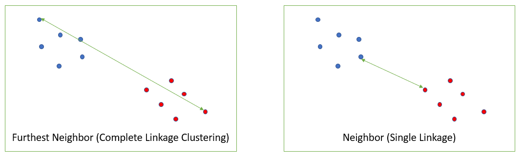
Which one you use (single linkage or complete linkage) depends on your data and what you want to achieve by clustering. Single linkage can result in long stringy clusters and “chaining” while complete linkage tends to make highly compact clusters [1].
One disadvantage of complete linkage clustering is that it behaves badly when outliers are present [2]. This is not a problem with single linkage.
Example of Complete Linkage Clustering
The following distance matrix shows pairwise distances between elements A, B, C, and D:
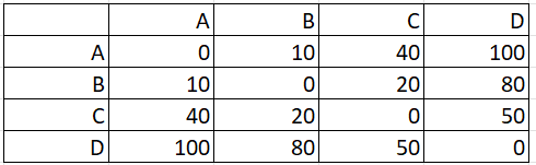
Step 1: Identify the pair with the shortest distance. For this example, that’s A, B.
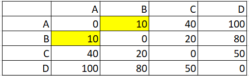
In this distance matrix, the shortest distance (highlighted in yellow) is between pairs A and B.
Step 2: Make a new matrix with the combined pair (from Step 1). At this stage, we know the diagonal will be all zeros (because the distance between any point and itself is zero):
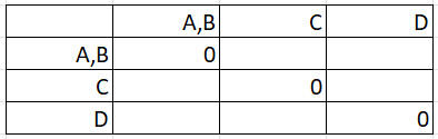
The matrix is reflected across the diagonal, so we only need to find values for the lower half (below the row of zeros).
Step 3: Fill in the first blank entry by finding the maximum distance. The first blank entry is at the intersection of C and A,B:
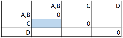
Looking in the matrix from Step 1, the distance C to A is 40 and C to B is 20:
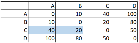
The maximum of these two distances (40 & 20) is 40, so that gets placed in the cell:
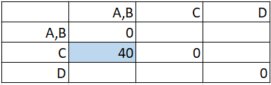
Step 4: Fill in the remaining boxes, finding the maximum distance between pairs, repeating the technique in Step 3:
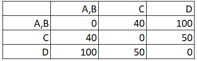
Step 5: Repeat Steps 2 to 4 on the new matrix you created in Step 4 above. In other words, your Step 4 matrix becomes your new Step 1 matrix. If you find the max distances for these new pairs, you should end up with:
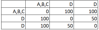
Continue until all items have been clustered. For this example, you have to work through the steps one more time to get:
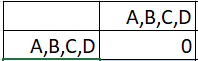
References
[1] Adams, R. Hierarchical Clustering. Article posted on Princeton.edu. Retrieved November 22, 2021 from: https://www.cs.princeton.edu/courses/archive/fall18/cos324/files/hierarchical-clustering.pdf
[2] Milligan, G. W. (1980). An examination of the effect of six types of error perturbation on fifteen clustering algorithms. Psychometrika, 45, 325–342
date-created: 2024-07-07 11:49:44 date-modified: 2024-07-08 12:56:28
Intuitions on L1 and L2 Regularisation - Towards Data Science
anchored to 116.00_anchor_machine_learning tags: #machinelearning #math #deeplearning
source: towardsdatascience.com author: Raimi Karim
reading time: 9–11 minutes
Introduction
Overfitting is a phenomenon that occurs when a machine learning or statistics model is tailored to a particular dataset and is unable to generalise to other datasets. This usually happens in complex models, like deep neural networks.
Regularisation is a process of introducing additional information in order to prevent overfitting. The focus for this article is L1 and L2 regularisation.
There are many explanations out there but honestly, they are a little too abstract, and I’d probably forget them and end up visiting these pages, only to forget again. In this article, I will be sharing with you some intuitions why L1 and L2 work by explaining using gradient descent. Gradient descent is simply a method to find the ‘right’ coefficients through iterative updates using the value of the gradient. (This article shows how gradient descent can be used in a simple linear regression.)
0) What’s L1 and L2?
L1 and L2 regularisation owes its name to L1 and L2 norm of a vector w respectively. Here’s a primer on norms:

1-norm (also known as L1 norm)

2-norm (also known as L2 norm or Euclidean norm)

p-norm
<change log: missed out taking the absolutes for 2-norm and p-norm>
A linear regression model that implements L1 norm for regularisation is called lasso regression, and one that implements (squared) L2 norm for regularisation is called ridge regression. To implement these two, note that the linear regression model stays the same:

but it is the calculation of the loss function that includes these regularisation terms:

Loss function with no regularisation

Loss function with L1 regularisation

Loss function with L2 regularisation
Note: Strictly speaking, the last equation (ridge regression) is a loss function with squared L2 norm of the weights (notice the absence of the square root). (Thank you Max Pechyonkin for highlighting this!)
The regularisation terms are ‘constraints’ by which an optimisation algorithm must ‘adhere to’ when minimising the loss function, apart from having to minimise the error between the true y and the predicted ŷ.
1) Model
Let’s define a model to see how L1 and L2 work. For simplicity, we define a simple linear regression model ŷ with one independent variable.

Here I have used the deep learning conventions w (‘weight’) and b (‘bias’).
In practice, simple linear regression models are not prone to overfitting. As mentioned in the introduction, deep learning models are more susceptible to such problems due to their model complexity.
As such, do note that the expressions used in this article are easily extended to more complex models, not limited to linear regression.
2) Loss Functions
To demonstrate the effect of L1 and L2 regularisation, let’s fit our linear regression model using 3 different loss functions/objectives:
- L
- L1
- L2
Our objective is to minimise these different losses.
2.1) Loss function with no regularisation
We define the loss function L as the squared error, where error is the difference between y (the true value) and ŷ (the predicted value).

Let’s assume our model will be overfitted using this loss function.
2.2) Loss function with L1 regularisation
Based on the above loss function, adding an L1 regularisation term to it looks like this:

where the regularisation parameter λ > 0 is manually tuned. Let’s call this loss function L1. Note that |w| is differentiable everywhere except when w=0, as shown below. We will need this later.

2.3) Loss function with L2 regularisation
Similarly, adding an L2 regularisation term to L looks like this:

where again, λ > 0.
3) Gradient Descent
Now, let’s solve the linear regression model using gradient descent optimisation based on the 3 loss functions defined above_._ Recall that updating the parameter w in gradient descent is as follows:

Let’s substitute the last term in the above equation with the gradient of L_,_ L1 and L2 w.r.t. w.
L:

L1:

L2:

4) How is overfitting prevented?
From here onwards, let’s perform the following substitutions on the equations above (for better readability):
- η = 1,
- H = 2x(wx+b-y)
which give us
L:

L1:

L2:

4.1) With vs. Without Regularisation
Observe the differences between the weight updates with the regularisation parameter λ and without it. Here are some intuitions.
Intuition A:
Let’s say with Equation 0, calculating w-H gives us a w value that leads to overfitting. Then, intuitively, Equations {1.1, 1.2 and 2} will reduce the chances of overfitting because introducing λ makes us shift away from the very w that was going to cause us overfitting problems in the previous sentence.
Intuition B:
Let’s say an overfitted model means that we have a w value that is perfect for our model. ‘Perfect’ meaning if we substituted the data (x) back in the model, our prediction ŷ will be very, very close to the true y. Sure, it’s good, but we don’t want perfect. Why? Because this means our model is only meant for the dataset which we trained on. This means our model will produce predictions that are far off from the true value for other datasets. So we settle for less than perfect, with the hope that our model can also get close predictions with other data. To do this, we ‘taint’ this perfect w in Equation 0 with a penalty term λ. This gives us Equations {1.1, 1.2 and 2}.
Intuition C:
Notice that H (as defined here) is dependent on the model (w and b) and the data (x and y). Updating the weights based only on the model and data in Equation 0 can lead to overfitting, which leads to poor generalisation. On the other hand, in Equations {1.1, 1.2 and 2}, the final value of w is not only influenced by the model and data, but also by a predefined parameter λ which is independent of the model and data. Thus, we can prevent overfitting if we set an appropriate value of λ, though too large a value will cause the model to be severely underfitted.
Intuition D:
Edden Gerber (thanks!) has provided an intuition about the direction toward which our solution is being shifted. Have a look in the comments: https://medium.com/@edden.gerber/thanks-for-the-article-1003ad7478b2
4.2) L1 vs. L2
We shall now focus our attention to L1 and L2, and rewrite Equations {1.1, 1.2 and 2} by rearranging their λ and H terms as follows:
L1:

L2:

Compare the second term of each of the equation above. Apart from H, the change in w depends on the ±λ term or the -2_λ_w term, which highlight the influence of the following:
- sign of current w (L1, L2)
- magnitude of current w (L2)
- doubling of the regularisation parameter (L2)
While weight updates using L1 are influenced by the first point, weight updates from L2 are influenced by all the three points. While I have made this comparison just based on the iterative equation update, please note that this does not mean that one is ‘better’ than the other.
For now, let’s see below how a regularisation effect from L1 can be attained just by the sign of the current w.
4.3) L1’s Effect on pushing towards 0 (sparsity)
Take a look at L1 in Equation 3.1. If w is positive, the regularisation parameter λ>0 will push w to be less positive, by subtracting λ from w. Conversely in Equation 3.2, if w is negative, λ will be added to w, pushing it to be less negative. Hence, this has the effect of pushing w towards 0.
This is of course pointless in a 1-variable linear regression model, but will prove its prowess to ‘remove’ useless variables in multivariate regression models. ==You can also think of L1 as== ==reducing the number of features== ==in the model altogether==. Here is an arbitrary example of L1 trying to ‘push’ some variables in a multivariate linear regression model:

So how does pushing w towards 0 help in overfitting in L1 regularisation? As mentioned above, as w goes to 0, we are reducing the number of features by reducing the variable importance. In the equation above, we see that x_2, x_4 and x_5 are almost ‘useless’ because of their small coefficients, hence we can remove them from the equation. This in turn reduces the model complexity, making our model simpler. A simpler model can reduce the chances of overfitting.
Note
While L1 has the influence of pushing weights towards 0 and L2 does not, this does not imply that weights are not able to reach close to 0 due to L2.
If you find any part of the article confusing, feel free to highlight and leave a response. Additionally, if have any feedback or suggestions how to improve this article, please do leave a comment below!
Special thanks to Yu Xuan, Ren Jie, Daniel and Derek for ideas, suggestions and corrections to this article. Also thank you C Gam for pointing out the mistake in the derivative.
Follow me on Twitter @remykarem or LinkedIn. You may also reach out to me via raimi.bkarim@gmail.com. Feel free to visit my website at remykarem.github.io.
Verständnis | Regularisierung
In dem Ausdruck steht für die L2-Norm von , die auch als euklidische Norm bekannt ist. Die Werte und haben folgende Bedeutungen:
- bezieht sich auf die L2-Norm von , die definiert ist als die Quadratwurzel der Summe der Quadrate der Elemente von . Mathematisch ausgedrückt ist die L2-Norm von wie folgt:
- Das Quadratzeichen in bedeutet, dass wir die L2-Norm quadrieren. Das Quadrat der L2-Norm wird berechnet, indem jedes Element der L2-Norm quadriert und dann summiert wird. Mathematisch ausgedrückt:
- Der Index in gibt an, dass es sich um die L2-Norm handelt. In der Regel wird die L2-Norm auch als euklidische Norm bezeichnet, da sie die euklidische Distanz im n-dimensionalen Raum darstellt.
Zusammenfassend bedeutet also die quadrierte L2-Norm von , die die Summe der Quadrate der Elemente des Vektors darstellt.
date-created: 2024-06-25 02:20:14 date-modified: 2024-06-28 07:25:06
Deep Learning
anchored to 116.00_anchor_machine_learning proceeds from 116.13_neural_networks Tags: #Study #machinelearning
Overview
Wir haben jetzt, aus 116.13_neural_networks gelernt, wie wir ein Neuronales Netz bauen und konstruieren können, sodass wir ein beliebiges Problem lösen können.
Dabei haben wir folgende Toolbox definiert / aufgebaut:
- Netzwerarchitektur auswählen
- Loss auswählen - passend
- Gradient-basierter Optimierer auswählen
- trainieren
Dabei haben wir wieder den Unterschied zwischen der Regression und Klassifikation betrachten:
Regression:
- Ausgabe ist kontinuierlich - gemäß der Prediction
- Square loss zum optimieren
- Ausgabe ist linear
Klassifikation:
- Ausgabe sind diskret –> ist die Klasse oder nicht!
- Nutzen ähnlichen Trick, wie bei logistischer Regression:
- WSk kann man durch die Sigmoid-Funktion darstellen!
- wir nutzen dann damit die Cross-Entropy-Loss Function1
Deep-Learning | Grundlagen
Wir haben bereits 116.13_neural_networks kennengelernt, wobei sie immer einen Input, einen Output und beliebige hidden layer hatten. Wir wollen das Konzept der hidden layer jetzt Grundlegend Skalieren, um so mehr Aussagen bzw. bessere Konstrukte darstellen zu können!
Dabei werden auch neue Probleme auftreten, die wir bearbeiten und lösen möchten!
[!Feedback] Motivation für Deep Learning
Es gibt diverse Aspekte, weswegen deep learning eingeführt / betrachtet wurde:
- mehr Rechenleistung zur Verfügung stehend –> gerade hohe parallelität kann viele Berechnungen vereinfachen / beschleunigen –> Damit sind größere Neuronale Netz möglich
- Bilderkennung / Spracherkennung / Sprachverarbeitung etc profitieren von diesen komplexen Netzen
- hat dazu beigetragen einen Durchbruch bei vielen ML-System zu erleben (etwa generative Modelle)
Definition von Deep-Neural-Networks
[!Definition] DNN - Deep neural networks
Deep neural networks beschreiben grundlegend wieder neuronale Netze, aber mit ein paar additionalen Aspekten / Parametern.
_Was beschreiben wir also mit einem DNN, welchen Vorteil hat diese Struktur? Und welche Herausforderungen erhalten wir dabei? #card
DNNs sind neuronale Netzwerke, die einfach viele hidden layer aufweisen
- die Hidden layer lernen dann die Merkmale unserer Eingabedaten mit steigender Abstraktion – desto tiefer wir sind
- Es wird ein End-To-End Training angewadnt –> wir nutzen Back-prop halt vom rechten Ende zum linken Ende des Netzes (müssen alle Schichten traversieren)
Gründe, warum wir viele Layer hinzufügen sollten / könnenn.
- komplexere Funktionen können modelliert / dargestellt werden!
- es erhält eine höhere Kapazität also kann mit mehr Daten besser werden
- wir müssen uns selbst wenige “Gedanken machen, wie man Parameter wählt” –> Das Netz brauch weniger menschlichen Input
Herausforderungen, die dabei auftreten:
- Mehr Speicher (Parameter) und Rechenleistung (trainieren eines tiefen, großen Netzes!)
- explodierende / verschwindende Outputs (exploding / vanishing outputs)
- ebenfalls explodierende / verschwindende Gradienten (exploding / vanishing gradients)
Wir möchten ferner die Initialwerte für die Gewichte des DNN betrachten und darüber urteilen / Probleme finden und Lösungen schaffen!
Exploding | Vanishing Outputs
Wir möchten die Problematik von exploding/vanishing outputs definieren:
[!Req] Exploding | Vanishing outputs
Betrachten wir folgendes neuronales Netz.
Wir können hier etwa den Forward-Pass ( die Berechnung von ) betrachten:
Angenommen die roten Gewicht im Layer sind gleich und alle anderen Gewicht (noch) null. Wass passiert dann mit dem Ouptut? Welches Problem erhalten wir? #card
Gilt diese Annahme, dann folgt also es wird direkt durchgeleitet.
Es folgen zwei Folgerungen:
und wenn
Das heißt die Outputs können dann sehr sehr klein werden oder aber auch explodieren –> Wenn wir die Wichtungen nicht gut initialisieren.

Exploding | Vanishing Gradients
selbiges Problem, wie bei Outputs können wir das auch bei den Gradienten betrachten und somit weiter aufzeigen, warum es wichtig ist die Wichtungen richtig zu initialisieren!
[!Req] Exploding | Vanishing Gradients
Betrachten wir wieder ein neuronales Netz:
Dann betrachten wir jetzt Backward-Pass (also Backprop), das heißt wir betrachten die Berechnung:
Was kann jetzt mit den Gradienten passieren, wenn wir die Werte groß / klein wählen? #card
Wir multiplizieren hier immer mit - etwa bei für ein großes –> Das heißt es wird sehr klein, wenn groß im negativen/positiven ist!
–> Dadurch können die Gradienten verschwindend klein werden, wenn wir große / kleine s initialisieren!
Dadurch sehen wir jetzt, dass wir eine neue Aktivierungsfunktion oder eben eine gute Initialisieung!

Motivation | Faktoren von starken Deep-Networks
mit obiger Erweiterung des Begriffes von neuronalen Netzen möchten wir jetzt Faktoren bestimmen und beschreiben, weswegen neuronale Netze so funktionsfähig und mächtig (geworden) sind.
- Aktivierungsfunktion ohne verschwindende Gradienten: ReLU und ¨ahnliche
- Skip-Connections / Residual Learning
- Autodifferentiation (autodiff)
- Optimierer (z.B. RMSProp, Adam)
- Architekturen mit unterschiedlichen inductiven Biasen:
- Convolution Networks
- Graph Nets
- Recurrent Networks
- Transformers
[!Attention]
Es werden jetzt einige Anpassungen / Erweiterungen notwendig sein, damit wir die obigen Herausforderungen zu beheben.
Aktivierungsfunktionen (für Hidden Layers) : ReLU
Wir möchten eine neue Aktivierungsfunktion betrachten, welche die vorher definierten / betrachteten - Sigmoid / tanh etc. - ersetzen kann / wird.
[!Definition]
Wir betrachten also die ReLU - Rectified Linear Unit :
Unter Betrachtung des Funktionswertes, wie ist die ReLU definiert? Welchen Vorteil erkennen wir bei Eingaben ? Wozu führt sie weiter? #card
Die ReLU ist folgend definiert:
Was wir hier beobachten können: für sehr große sättigt sie sich nicht - im Vergleich zu etc –> das heißt sie wird nicht zwischen stuck sein
-> Sie führt dadurch auch zu einer sparse Repräsentation –> denn manche hidden Aktivierungen könnten dann auch 0 sein.
Problem: Wenn wir jetzt haben, dann lernen wir nichts, weil entsprechend resultieren wird.

Wir haben bei der ReLU jetzt folglich das Problem, dass dazu führen würde, dass wir keine Werte erhalten –> nicht lernen.
Dem möchten wir mit einer angepassten ReLU Funktion entgegentreten:
[!Req] L-ReLU - leaky ReLU
Was ändern wir bei der L-ReLU - sodass sie auch für Werte kleiner 0 lernen kann / einen sinnigen Wert ausgibt? #card
Wir wollen die Leaky ReLU jetzt folgend definieren:
ist dabei typischerweise relativ klein gewählt, damit es nicht zu viel Einfluss nimmt ( es einfach verhindert, dass 0 auftritt); meist etwa

Wichtigkeit der Initialisierung
Wie in Task 3 Training a Neural Network schon gesehen sind die Initialparameter sehr wichtig, um entsprechende Ergebnisse mit einem neuronalen-Netz zu erhalten.
Das werden wir ferner formaler beobachten und eine Lösung vorschlagen.
[!Definition] Initialisierung | Probleme
Wir möchten ferner ein Beispiel-Netz betrachten (nur High-Level) und hierbei verschiedene Startparameter für die Gewichte einsetzen und beobachten.
Unter Betrachtung des folgenden Netzes, was passiert, wenn wir Nullgewichte einfügen? Was passiert mit normalverteilten Gewichten? Was passiert bei skalierten normalverteilten Gewichten? #card
Unter Einsetzen von Nullgewichten werden wir sehen, dass die Aktivierungen der Schichten einfach bei stehen bleiben werden:
Unter Einsetzen von Normalverteilten Gewichten werden wir folglich sehen, dass die Aktivierungen schnell gesättigt sein werden und somit gerade in die Extrema peaken:
Sofern wir jetzt gut skalierte normalverteilte Gewichte verwenden, werden wir auch in den Aktivierungen eine Normalverteilung beobachten –> Sie ist also ausgeglichener:


Wir sehen also, dass es relevant ist, wie die Initialisierung umgesetzt wird.
[!Feedback] Wichtigkeit am Beispiel einsehen:
Folgend ein Link, der die Wichtigkeit / das Problem darstellen kann:
https://www.deeplearning.ai/ai-notes/initialization/index.html
Ferner haben wir herausgefunden, dass eine skalierte Gewichtsverteilung optimal wäre / ist.
Skalieren der Anfangs Gewichtsverteilung
[!Bem] Finden der optimalen Gewichte
Wir möchten ferner unter Betrachtung der Eingabewerte x also eine optimale Initial-Wichtung erzeugen.
Angenommen die Eingangsdaten und die Gewichte sind normalvertetilg, also und die Gewichte Wir suchen also noch die Varianz und fordern hier folgend:
- Die Varianz der Aktivierung sollte gleich bleiben!
Wir nehmen jetzt an, dass die Aktivierungsfunktion mehr oder weniger linear ist (etwa bei mit kleinem ) Wie ist die Varianz der Aktivierung eines hidden layers dann bestimmt? #card
Die Aktivierung ist dann das Produkt von zwei unabhängigen Normalverteilungen was wir folgend aufteilen können (da iid.): Es folgt dann:
(Für die Gradientenberechnung - dem Backward-Pass! - können wir dann ähnlich argumentieren!)
[!Beweis] Praxisanwendung
Man nimmt hier meist bestimmte Initialisierungen:
- Xavier
- Glorot
- He Initialisierung (bei ReLU)
Automatic Differentiation
Als Ausblick, wie die Berechnung der Ableitungen für [Back-prob ()](116.13_neural_networks.md#Back-prob%20()) etwas automatisiert werden kann - weil es sonst aufwendig und vor Allem manuell gemacht werden muss - möchten wir einen Ansatz betrachten, welcher diese Ableitung berechnet:
[!Idea]
Betrachten wir also folgende Beispiel-Funktion, die wir ableiten wollen: , was unsere typische Aktivierungsfunktion sein kann.
Wir können jetzt einen Execution Tree anschauen und damit den Term aufgliedern:
Im Beispiel erhalten wir etwa folgende Struktur:
-> Wir könenn also die Funktion/ den Code zur Auswertung des Ausdruckes Generieren
-> Ferner können wir auch die Ableitung davon dann erzeugen lassen
- Das kommt daher, dass wir relativ einfach die Ableitung der einzelnen Fragmente bestimmen und anschließend unter Anwendung der Kettenregel entsprechend umformen können

Training Speed | Konvergenz verbessern
[!Hinweis] Motivation
Während gradient descent prinzipiell nicht schlecht ist und dabei hilft die Minima zu finden, sind die leider langsam.
Weiterhin können sie teils falsch konvergieren / oder nicht und daher brauch es also weitere Intervention.
Wir wollen dafür jetzt drei verschiedene Methoden betrachten, die helfen sollen, das zu verbessern!
Momentum
[!Definition] Gradient Descent mit Momentum
Wenn wir den Loss optimieren wollen, kann diese Funktion in der Übersicht viele “Klüfte, Hänge und Grobheiten” aufweisen - also wir uns da etwa verhängen, wenn wir nur lokale Minima suchen.
Visuell etwa:
Wenn wir die Loss-Funktion schon als Terrain betrachten, kann man jetzt durch eine passende Analogie einen neuen Ansatz für einen besseren Gradient-Descent anschauen:
Setzen wir folgende Analogie: Gradient Descent ist wie ein Ball, der eine Oberfläche hinunterrollt. Wir bauen durch dessen Masse/Trägheit jetzt ein Momentum auf, das uns dabei helfen kann, das optimale Minimum zu finden. Wie können wir genau das passend modellieren und umsetzen? #card
Wir setzen das Momentum so um, dass wir immer den Durchschnitt von vergangenen Gradienten - die Menge kann variieren! - behalten und in die Berechnung einbeziehen.
Wir berechnen sie dann folgend: wobei hier:
- die Gradientenschritte nummeriert
- der Mittlungsparameter ist (meist so )
Wir werden jetzt die Gewichte immer entsprechend des geglättenden Gradienten anpassen, also:
Vorteile:
- wir vermeiden Oszillation ( zwischen einem Tal hin und her!)
- kleinere lokale Minima kann man überwinden (wir rollen drüber)
- flache Regionen und zerklüftete Loss-Oberflächen werden auch entsprechend traversiert (schneller)

Exponential Moving Averages
Wir wollen folgend betrachten, wie man unter Vorliegen von Elementen , wobei (ein Zeitindex ist) den Durchschnitt berechnet, mit der Prämisse, dass wir die jüngste Vergangenheit (also nur Elemente aus der Menge) dafür nutzen möchten.
Normalerweise berechnen wir den Durchschnitt einfach mit
wir wollen jetzt aber nur aus der selektierten Menge den Durchschnitt bilden:
[!Req] Umsetzung des Durchschnittes der jüngsten Vergangenheit
Wenn wir jetzt also den Durchschnitt für eine selektive Menge von Zeitdaten berechnen wollen, brauchen wir eben diese Werte von , also
wie können wir das mit EMA umsetzen? welche vorteile hat das? Wozu wird alpha in der Formel genutzt? #card
Wir bräuchten, um immer die recenten Werte zu speichern, also mehr Speicher - neben der Speicherung aller Daten - und somit möchten wir eine andere Struktur betrachten.
Wir wenden hierbei die EMA - Exponentiell gleitende Durchschnitte - an, die die jüngste Vergangenheit stärker berücksichtigen, als die ältere, dabei aber keinen weiteren Speicher brauchen!
Wir können sie folgend beschreiben:
Hierbei gibt der Parameter die Länge des Durchschnittes an
er wird aktualisiert und berücksichtigt einen Teil des Durchschnitttes durch einen Teil des neuen Inputs - den wir jetzt etwa hinzugefügt haben. Ferner gilt:
- gibt uns keinen Durchschnitt und wir nehmen einfach die Werte direkt
- für dominiert der Durchschnitt den gesamten Wert ( weil die Wichtung davon halt steigt)
- meistens ist der effektive Durchschnittshorizont
Learning Rates
Ein weiteres Maß, was uns hilft den Gradientenabstieg zu verbessern, ist das aktive Anpassen der Learning Rates!
[!Definition]
Wir wissen, dass beim Gradientenabstieg mit die Lernrate das Ausmaß der Änderung der Parameter pro Schritte angibt.
Wir wissen, dass eine feste Lernrate nicht so optimal ist und wir somit eine bessere Lösung finden wollen.
was wäre eine Möglichkeit diese Learning-Rate anpassungsfähig zu machen #card
Man könnte etwa immer mit großen Updates anfangen ( also groß) und dann Schritt für Schritt kleinere wählen. Also etwa mit
Besser wäre noch weiter:
- adaptive learning rates –> also solche, die aufgrund von Parametern anpassen und somit verschieden skalieren können
- Lernraten schedule: Lernratenabnahme um nach einigen Epochen und weiterhin kosinusförmige Lernraten.
Wir wollen ferner Adaptive Learning Rates genauer betrachten und einige Varianten dafür betrachten.
Adaptive Learning Rates | RMSprop
[!Bsp] RMSprop - Root Mean Square Propagation
Als Grundlegende Idee: wir skalieren die Lernrate pro Parameter/Gewicht, um dabei eine ähnliche Update-Größe zu erhalten.
Wir werden also den Durchschnitt über die Magnituden der vergangenen Gradienten komponentenweise (also für jedes Gewicht) berechnen. Das machen wir folgend:
was können wir aus dieser Betrachtung ziehen, wie skalieren wir? Wie verhält sich die Lernrate? Was müssen wir nach Berechnung des obigen Durchschnittes anschließend tun? #card
- wir skalieren hier also die Lernrate umgekehrt proportional zur Größe des Gradienten
- dabei werden dann kleine Größen also zu einer erhöhten Lernrate führen
- ferner könenn wir hiermit vanishing / exploding Gradients verhindern
haben wir dann den Durchschnitt entsprechend berechnet, werden wir anschließend den Gradienten der skalierten Lernrate anwenden:
Wir verwenden hier nur um die Division mit 0 zu verhindern xd. Daher ist er meist auch sehr klein:
- nennen wir dann also den Regularisierer
- ist meistens und gibt an, wie viele vergangene Gradienten wir berücksichtigen / einbeziehen! (das wären damit also 1000 Stück)
Adaptive Learning Rates | Adam
Adam verwendet RMSprop und auch Momentum, merged also beide Ansätze zusammen!
[!Definition] Adam
Als Kernidee formulieren wir: Wir skalieren die Lernrate jedes Parameters durch die Mittelwerte/Magnituden!
Wir berechnen in diesem Modell also folgend die Mittelwerte des Gradienten (Mittelwert) und dessen Varianz - sie ist nicht zentriert! - folgend: und die Varianz mit
(Bedenke, dass wir das wieder für jeden einzelnen Parameter machen!)
Was müssen wir anschließend noch tun, wie? #card
Wir müssen dann noch den mittleren Gradienten skaliert anwenden - wie bei RMSProp:
Wir resultieren hierbei ähnlich wie bei den Signal-Rausch-Verhältnissen!
- kleiner Mittelwert und große Varianz: viel Rauschen, kleine Lenrrate
- großer Mittelwerrt und große Varianz: vertrauenwürdiges Signal, normale Lernrate
[!Tip] Umsetzung von Adam
Wir wollen Adam mehr oder weniger anwenden:
womit beginnen wir, was muss danach bzgl. des Bias folgen? Was sind Standardwerte für mu,eta,beta,epsilon? #card
Zunächst möchten wir also und - die ersten beiden Momente, die wir definieren - mit 0 ansetzen!
–> Es wird nun eine Bias-Korrektur durchgeführt, um den Bias aus der Initialisierung zu entfernen! Dafür korrigieren wir und !
und weiter: ( meint hier den Exponent beim Zeitschritt !)
–> Folgerung: Da erhalten wir ( siehe geometrische Reihen) und somit passiert diese Korrektur nur am Anfang!
Standardparameter wären ferner:
- ( ist aber stabiler)
Bemerkung | Einordnung
[!Bsp] Folgerungen zu adaptive learning rates
Tatsächlich ist der Squared-Descent-Gradient (SDG) mit gut abgestimmten Learning Rates meist schon sehr gut / konkurrenzfähig!
Adaptive Learning Rates Adam ist der De-Facto-Standard, da er weniger Parameterabstimmungen erfordert!
Man entwickelt diese Optimizer für die Learning Rate primär für den Trainingstart, jedoch laufen sie während des gesamten Trainings weiter / sind aktiv.
Es gibt hier noch viele weitere Optimizer, jedoch gibt es keinen überlegenen (noch!)
- Entweder man verwendet einen Optimizer und prüft verschiedene Hyperparameter
- oder man probiert die gleiche Anzahl unterschiedlicher Optimizer mit ihren Standards
-> Bei beiden werden wir dann ähnliche Ergebnisse erhalten!
Batch-Normalization
Wir wollen jetzt noch eine Optimierung betrachten, die darauf abzielt die Layer des DNN so anzupassen, das sie alle ähnliche normalisierte! Aktiverungen haben.
[!Definition] BachtNorm
Was beschreiben wir mit der Batch-Norm? #card
Wir normalisieren die Aktivierung jedes Neurons, sodass der Mittelwert und die Varianz innerhalb jedes mini-batches ist (also wir wollen eine Standardverteilung erhalten(?))
wir fügen dann lernbare Parameter hinzu, um die normalisierten Werte zu skalieren und /oder zu verschieben.
Für einen Mini-Batch berücksichtigen wir (also in dem Layer die Berechnung der Werte ()) mit dem Mittelwert und der Standardabweichung folgend: -> Wir normalisieren die Pre-Aktivierung der Hidden unit folgend:
Danach skalieren und verschieben wir diese folgend: wobei:
- und ebenfalls durch den Gradient Descent gelernt werden (können/müssen actually).
- –> Damit erreichen wir eine schnellere Trainingskonvergenz!
Wir wollen das ganz konkret für einen beliebigen Punkt berechnen!
[!Feedback]
Um klarzustellen, wie der Mittelwert und die Standardabweichung berechnet werden:
Für ein Batch mit Datenpunkten erhalten wir folgend den angepassten Wert des Batches folgend:
Wie können wir ihn berechnen? Welche Vorteile und Nachteile ziehen wir hieraus? #card
Vorteile, die wir erhalten:
- es verbessert den Gradientenfluss –> vanishing / exploding gradients werden verhindert
- ermöglicht hohe Learning rates - ohne direkt über die Ziele zu schießen!
- es reduziert die Empfindlichkeit gegenüber der Initialisierung
- Wir erhalten hier eine Regularisierung! –> Es fügt ein Rauschen zu den Aktivierungen innerhalb der Layer hinzu –> damit haben wir ein Measure gegen Overfitting! erhalten!
Nachteile/Überlegungen dazu:
- Bei der Batch-Norm werden die “Layers” typischerweise vor der Aktivierungsfunktion platziert!
- für jedes batch wird der Mittelwert und die Varianz berechnet, während des Trainings zumindest!
- bei der Inferenz: –> ein gleitender Durchschnitt dieser Statistiken während des Trainings - oder dem Testbatch <– wird angewandt.
- man brauch eine sorgfältige Implementierung dieser Struktur/ Idee
Convolutional Neural Networks #refactor
Wir haben bis dato immer vollständig verbundene Netze betrachtet und analysiert. Damit werden also alle Eingaben mit der gleichen Relevanz behandelt. und somit alle betrachtet.
[!Hinweis] Problem bei der Betrachtung aller Eingaben
(Am Beispiel von Bilderkennung)
Welches Problem haben wir, wenn wir immer alle Eingaben betrachten und daraus ein Netz bilden/ trainieren? #card
Betrachten wir etwa ein Bild der Größe Eingaben (also Pixel), dann sehen wir hier schon, dass es immens groß wird und bei steigender Größe nur noch schlimmer wird.
Weiterhin: wenn sich etwa ein Bild nur minimal ändert -> für Menschen etwa gar nicht so sehr - werden die Daten schon signifkant anders sein und somit eventuell das Modell beeinflussen ( wenn wir etwa ein Bild nach rechts verschieben oder anders croppen
–> Wir wollen also irgendwie die Dichte von Informationen verstärken bzw. so anpassen, dass wichtige Daten aufgenommen und betrachtet werden können, während unwichtige Dinge herausgelassen werden.
Ferner können wir dafür etwa folgende Aspekte betrachten:
- lokale Strukturen existieren (bei Bildern)
- Verschiebungen von Bildern um einen Pixel sollte die Semantik des Bildes nicht verändern

Wir möchten uns dafür jetzt einige Techniken anschauen, die helfen die Informationen zu reduzieren und die wichtigsten zu erhalten / zu filtern.
Lokalität und Verschiebungsinvarianz ausnutzen | Convolution
[!Idea]
Wie obig benannt, wollen wir jetzt das Netzwerk auf weniger Input laufen lassen, indem wir die Darstellung von lokalen Strukturen anwenden und ferner auch die Verschiebungsinvarianz anwenden
Was können wir hieraus machen, was sind convolutional layers? #card
Aus dieser Betrachtung wollen wir dann jetzt Convolutional Layers bauen:
- Jede Einheit schaut hierbei nur ein kleines Fenster des gesamten Bildes an
- Jede Einheit berechnet aber auch genau das Gleiche –> Deterministisch
Damit können wir dann das Bild in seiner Menge verringern, aber die wichtigen Daten behalten!
Das wird folgend umgesetzt:
[!Definition] Convolutional Layers
betrachten wir die obige Grafik, wie funktioniert die Konvolution hier? #card
Wir wenden einen Kernel an, welcher quasi ais Filter agiert und uns dabei helfen wird bestimmte Daten aus einer großen Menge zu extrahieren / zu übernehmen.
Im Beispiel werden wir etwa wie folgt vorgehen:


[!Definition] Convolution Layer / Berechnung
Wir wollen das Konzept ferner noch formal beschreiben:
Betrachten wir also ein Eingangsbild:
Ferner brauchen wir noch die Gewichte –> sie werden das kleinere Bild bilden, welches reduziert wurde / ist.
Wie definieren wir jetzt den Kernel? Wo finden wir hier die Struktur, die wir später optimieren sollten ( also die Wichtung) und somit den Gradientenabstieg? Was passiert noch in der Praxis #card
Der Konvolutionskern / Kernel gibt die Gewichte an (bedenke, dass dieser Kernel für jeden Block angewandt wird!) und wird beschrieben mit:
Wir können dann sehen, wie wieder die Aktivierungsfunktion in dieser Idee gebunden / enthalten ist, denn: –> Wir wenden also für jeden Eintrag immer die Gewichte - welche im Kernel gespeichert sind an- und berechnen dann die Ausgabe.
Hier ist wieder der Bias
–> Das Bild kann dann also mit dem gelernten Filter gefiltert / bearbeitet werden!
Unter allen Einheiten werden die Parameter geteilt –> weil wir den Kernel mehrfach auf verschiedene Blöcke anwenden!
(In der Praxis): -> man hat meist mehrere Filter gleichzeitig auf ein Bild laufen –> es gibt also viele Kanäle, die das Bild verschieden “darstellen”
Convolutional Layers | Beispiel Pooling
Zuvor haben wir schon die Methode gesehen, bei welcher wir einen Kernel anwenden, um das Bild anzupassen.
Es gibt natürlich noch weitere Ideen / Ansätze:
[!Req] Definition | Max Pooling | Min Pooling
Wir möchten eine Reduktion der Größe von Bildern - der Darstellung dieser als Matrix - umsetzen.
Wie können wir das mit “Pooling” umsetzen? Welche zwei Arten betrachten wir? #card
Wir können hier Pooling anwenden, welches ein Bild durch eine definiere Größe ersetzt, also Matrizen.
Es gibt zwei Ansätze:
- Max-Pooling, was in den Kacheln der Größe den maximalen Wert nimmt
- Mean-Pooling, was in den Kacheln den mittleren Wert extrahiert@
Am Beispiel etwa:

Definition | Anwendung | CNNs
[!Feedback] Umsetzung eines CNN
Angenommen wir wollen für ein Eingabebild eine Erkennung von Inhalten bestimmen / berechnen:
Wie gehen wir mit diesem CNN vor? Welche Schritte durchläuft es? #card
Wie in der Grafik zu erkennen, durchlaufen wir mehrere Schichten, die verschiedene Aufgaben haben:
Es besteht grundsätzlich aus vielen Convolutional / Pooling Layers welche das Bild:
- in verschiedene Kanäle, meist einteilt ( mit verschiedenen Fokus quasi )
- es werden in den Layers die Gewichte geteilt!
- das Netz extrahiert Merkmale aus dem Bild
Ferner, weil wir immer weiter abstrahieren und “komprimieren”, werden wir immer weiter abstrahierte Convolutional layers

Weitere Anpassungen
Betrachten wir CNNs, dann sind hier noch weitere Aspekte notwendig, die dabei helfen, Bilder richtig zu reduzieren bzw. zu verarbeiten. Zwei dieser Konzepte wollen wir uns noch anschauen:
Padding
[!Definition]
Wir wissen, dass durch die Convolution die Dimension reduziert wird.
wie kann das behoben werden, wie wird es umgesetzt? #card
Durch Padding können wir diese Reduktion vermeiden, indem wir Nullen um das Bild drumherum setzen ( bevor durch den Kernel gefiltert wird!) und somit verlieren wir weniger Dimensionen.
Hierbei wird das Padding gewählt mit
Visuell also:

Stride
[!Definition] Stride
Wenn wir die Convolution ansetzen, werden wir den Kernel immer über das Bild setzen und somit nach und nach konvertieren.
Was gibt uns Stride an? #card
Mit Stride wird festgelegt um wie viele Pixel der Kernel immer verschoben wird –> damit wir etwa verhindern, dass bestimmte Bereiche mehrfach durch den Kernel bearbeitet werden.
Visuell etwa:

Bekannte Architekturen:
Mit das erste Netz, was in dieser Struktur funktionierte - aber nicht sehr gut war - ist das LeNet-5 ( Veröffentlich ==1998!==)
Es besteht aus etwa Gewichten und konnte einen Testfehler von auf dem MNIST-Datensatz erzielen!

AlexNet - von Krizhevsky (2012) (Hat sehr viel angestoßen, weil es so viel schneller / besser war, als die vorherigen!)

VGG - Simonyan und Zisserman (2012)
Ist auch relativ bekannt und schnell.
Hier ist die Hauptkomponente:
- Convolutional Kernels von der Größe im Gegensatz zu variablen Größen in AlexNet –> dadurch waren weniger Parameter notwendig!
GoogLeNet (2014 - Szegedy)
 (Ist riiesig!)
Das Inception-Modul besteht aus Convolutional Kernels () die parallel arbeiten und aggregiert werden. –> Jedes Inception-Modul kann dann Merkmale auf verschiedenen Ebenen erfassen
Es hat auch Zwischenoutputs, die man während des Trainings verwenden kann!
ImageNet –> Als Benchmark für CNN:
- großer Datensatz mit 14 Millionen Bildern mit 20.000 Kategorien!
- üblicher Ausschnitt ist ImageNet-1K mit 1.2 Millionen Bildern mit etwa 1000 Klassen
- Es gibt einen Wettbewerb, der den besten Recognizer kürt / sucht

[!Attention] Größer ist nicht immer besser!
Wir sehen folgend, dass mit größeren Netzen nicht zwingend bessere Werte erzielt werden können.

Overfitting verhindern: #refactor
[!Idea] Grund der Regularisierung
Wir haben jetzt starke Netze konstruiert, welche sich durch viele Schichten auf bestimmte Aufgaben spezialisieren und diese lernen können.
Es kann weiterhin zu Overfitting kommen
Das Auftreten des Overfittings möchten wir folgend unter Anwendung von zwei Methoden unterbinden oder verringern.
Early Stopping
[!Definition]
Wir wollen folgend ein Verfahren definieren, was mit folgender Grundprämisse beginnt und anschließend Overfitting verhindern möchte:
- unser neuronales Netz wird zu Beginn relativ kleine Gewichte aufweisen / haben
- Desto länger wir trainieren, desto höher wird die Komplexität des Netzes - und somit dessen Gewichte.
Wie können wir unter der Voraussetzung jetzt Overfitting verhindern? #card
Im Prinzip wird early Stopping snapshots von früheren Parametern machen und so, bei fortlaufendem Training, alte Parameter, die einen besseren Output bei der validation erhalten haben, wiederherstellen.
Wir versuchen also das Overfitting zu verhindern, indem wir auf einen älteren Zustand springen, wenn wir bemerken, dass unser Training für die validation schlechtere Werte ausgibt.
Regularisation via Weight Decay
[!Req]
Erinnern wir uns wieder an **Regularisierung | Ridge-Regression ** - wo wir auch einen Regularizer eingebracht haben, um bestimmte Gewichte “bestrafen” zu können, also Penalties für bestimmte, etwa große, Gewichte geben.
Was werden wir für diese Methode anwenden? Wie übt sich dieser beim Gradientenabstieg aus? #card
Wir fügen jetzt bei unserer Struktur auch einen Regularizer ein, welcher spezifisch große Gewichte “bestraft”:
Wobei hier die Regularisierungsstärke ist (wie stark der Einfluss ist)
Damit manifestiert er sich als ein “Weight Decay” Term während des Gradientenabstieg. Also folglich:
Das heißt, wenn das Gewicht sehr groß ist, wird dann entsprechend ein starker Penalty durch den Term verursacht und somit das Update für diesen Vektor einen starken Einfluss verursachen
some further resource might be found here: https://benihime91.github.io/blog/machinelearning/deeplearning/python3.x/tensorflow2.x/2020/10/08/adamW.html
Dropout
[!Example] Definition | Dropout
Wir wollen noch eine weitere Möglichkeit zur Verminderung von Overfitting betrachten.
Gehen wir dabei von folgender Prämisse aus:
- Unser Netzwerk lernt nach und nach Parameter und verwendet dabei “hoffentlich” Bereiche des Netzes, die es benötigt / wo aktiv viele Entscheidungen getroffen werden.
- Es sollte hierbei beim trainieren am besten zusätzliche Kapazitäten - die es nicht zwingend bräuchte - ignorieren.
Wie können wir daraus jetzt eine Struktur schaffen, die Overfitting vermindern kann? #card
Wir wollen folgendes Prinzip anwenden:
Wir erzeugen eine Regularisierung durch ein gesetztes Rauschen auf den hidden layers(units).
–> Damit kann es im Extremfall dazu kommen, dass manche Eingaben innerhalb der Einheiten vollständig ignoriert werden, etwa weil die Wichtung 0 ist.
Dropout beschreibt also:
- Es wird eine Eingabe- oder eine versteckte Einheit mit gewisser WSK in jedem Minibatch herausgenommen bzw. “deaktiviert” –> und das netz muss weiter trainieren und sich daran anpassen
- Wir können somit “zu starke Fokussierung auf bestimmte Parameter” verringern / verhindern
Verwendung von Domänewissen
[!Bsp] Definition
Wir kennen oft die Eigenschaften der Daten, die wir betrachten möchten - das können bestimmte Werte, Invarianzen etc sein.
Als Beispiel können wir eine Rotations/Skalierungsinvarianz betrachten:
Wie können wir diese Information jetzt in das Modell einbinden, sodass es besser erkennen oder gegen die Invarianzen einfacher vorgehen kann? #card
Wir können dem Modell jetzt über zwei Wege die Informationen über etwaige Eigenschaften - hier Invarianzen - der Daten zukommen lassen:
- Die Invarianz direkt in das Modell einbringen –> etwa erst eine Translation durchfuhren, sodass die Daten vereinheitlicht werden können o.ä.
- Die Loss-Funktion anpassen
- oder Data-Augmentation hinzufügen -> Also Transformierte Daten in den Trainingssatz mit einbringen

Data Augmentation
[!Req] Definition | Data Augmentation
Was ist gemeint, wenn wir data augmentation für unser Modell anwenden? #card
Mit Data Augmentation möchten wir Invarianzen o.ä. Eigenschaften unserer Daten explizit in das Modell und den Trainingssatz einbringen.
Das heißt, dass wir etwa diverse Trainingsbeispiele so modifizieren, dass sie etwa verschiedene Drehungen aufweisen, also die Invarianzen einbauen
Normalerweise sollte eine solche Augmentation / Transformation die Labels der abgebildeten Daten nicht ändern.
Betrachten wir Bilder, könnte das u.U. schon passieren.
–> Ist das ein Problem?!
Nicht wirklich, das Modell wird dennoch besser / sicherer


Phänomen: Double Descent | Bias-Variance-Trade-off++
[!Definition] Double Descent;
Es kann beobachtet werden, dass sehr große Netzwerke weniger stark overfitten. –> Dass das passiert ist “rätselfhaft”, aber es gibt eine Vermutung dafür:
Was beschreibt das “Double-Descent-Phänomen”? #card
(Hierbei gibt die X-Achse die Modellkomplexität (Menge der Parameter) an)
Weitere Infos dazu finden sich hier: link

cards-deck: 100-199_university::111-120_theoretic_cs::116_introduction_machine_learning
Overview of Machine learning
anchored to 116.00_anchor_machine_learning may requires prior knowledge from 105.00_math_stochastic and likely also information about 111.00_anchor
Overview
Some general ideas for the concept of machine learning compose:
[!Quote] Arthur Samuel - 1959 Field of study that gives computer the ability to learn without being explicitly programmed
[!Quote] Learning is any process by which a system improves performance from experience
Machine Learning is concerned with computer programs that automatically improve their performance through experience ~ Herber Alexander Simon - Turing Award 1975, Nobel price (business) 1978 )
Generally speaking: Machine learning is not Voodoo -> but is to use data to automatically find a suitable function or algorithm to solve a given task.
Below we may give an overview on how machine learning could be taken to use to solve tasks:
[!Example] possible usecases:
- Weather forecast We would like to have a system that is able to predict the weather / temperature on the next day, based on data supplied –> previous information it obtained may result with: temperature tomorrow =
- Disease diagnosis: Finding out whether a person is ill or not based on some information (images of tissues, blood data etc.) attempts to result with a function: –> probability
- Chat Bots predicting the outcome of for the next word(s) to answer a request
[!Tip] (Oliver G. Selfridge) Find a bug in a program and fix it and the program will work today. Show the program to find and fix a bug and the program will work forever
-> at least thats expected, but not feasible xd
Historic scope:

- back in the 1945s the first artificial intelligence structures were discussed -> ranging from being a simple computer to play go against or such.
- From 1980s Machine learning was flourishing -> coming into play are the aspects of
- with advancements in the field the whole topic of deep learning was developing fast starting in the 2010s
[!Tip] The friendship algorithm (TBBT)

[!Idea] Base concept of ML regarding available data and outputs #card?
The general idea to resolve problems in ML is by doing the following: Input: Data and the desired result - I want you to find cats in images Output: An algorithm that does this -I will find cats by doing things…
-> we reverse the usual approach to work with information/data
Supervised Learning
With Supervised learning we are partaking in one of three large categories for machine learning. Here particularly we have controlled learning of a machine because our data contains labels and information about the desired results of said data.
[!Definition] Supervised learning | concept #card
With supervised learning we are adapting/modifying the core principal of machine learning a little: input: data points where: is the input(data) and is the desired output - a label classifying what it should result with we have a space of function with elements Objective: We would like to find a function such that: for this given task –> we want to find / discover the function that is best at approximating the desired output for a given input -> to assure this: we measure the quality of this function :
proceeding to minimize the loss alltogether: ^1721145490688
This may be done in the following subjects:
- recognizing handwritten digits
- classifying cells -> pathology images
- recognizing faces or objects in an image / video-stream
- language modelling
- regression
Unsupervised Learning
Once again we strive for the base principle of machine learning: having data and wanting to find a function that best interprets it in a certain way.
[!Definition] Unsupervised Learning | basic idea #card
with unsupervised learning we don’t use labels on given data - as it was in supervised learning. We have the following constraints / basics: input data points with ( a vectorspace!) once again we are given a function space with and we would like to find a function so that: where is the low-dimensional representation –> This means we are reducing dimensions from high vector input (x is a vector of !) to a smaller space while still maintaining / not losing information on its traits - like its similarity to the original data point in this new representation we then assign each to a given cluster
Objective: The objective is not directly defined, its rather the goal to generally reduce the dimension of data somehow reliably - how exactly is not defined. –> there are many algorithms that could be found to solve this task ^1721145490694
This may be used in the following subjects:
- Genome comparisons ( this is clustering)
- Finding descriptors for face expressions ( dimension reduction –> from a high dim ( the face) to a lower -> Cartesian mapping of emotions)
- Finding disentangled generating factors ( take image of faces and find few descriptive variables – generating new maybe)
Reinforcement Learning
Is a little different in its idea compared to the previous to attempts to train machines. Here we utilize a reward system to have the system train itself and gain knowledge about performance and such.
[!Definition] Reinforcement learning in its core concept? #card we provide a system to interact with: -> is the state, is an action ( in time )
We have the Function space again with that denotes a (policy) deciding about actions to take based on the current state:
to evaluate / refine later we introduce a rewarding/utility function:
Objective: we ought to find the function that maximizes the expected reward
Generally speaking these stochastic systems are described with Markov Decision Processes.
Tasks of models in reinforcement learning are therefore:
- collect own data – to develop on / with
- simultaneously learn and potentially models of and (utilty funct and the system to interact with)
- the reward can be sparse – only at the end of an long action sequence or such ^1721145490696

Reinforcement learning can be deployed in various fields - obviously - like:
- robot control and movements
- Deepmind AlphaGo Robot -> game bots
- walking simulations
Usage of ML
Generally speaking we have a large objective with ML:
[!Definition] To solve problems where we do not have good algorithsm but data (a lot!)
It is involved in many many fields nowadays: daily life
- sorting pictures
- predicting what will be done (advertisment / content recommendation)
- diagnosis assistant in health
- access to knowledge -> LLM science:
- automatic processing of experimental data
- new tools for searcing in fast spaces - proetin confirmations or similar
Data privacy and security:
We ought to maintain caution of the origin of our used data: -> Machine learning systems are utilizing and working with data a lot hence its important to select and source it well
Could create:
- bias due to gender/race/ethnicity
- exploit information of people etc
Other fields:
- psychology
- computer science …
- statistics
Tutorium | Machine Learning
anchored to 116.00_anchor_machine_learning
First tutorial
First Task1:
b: Shifting to right will cause issues because we completely change the vector that is representing the tempalte in the given character.
The difference between two images with a shifted template will compute a whole different distance hence it will obviously be completely different than the previous template.
d Using grids will average values over a large area of the image, hence a variation - like a shift - wont have much of an impact However detailed grids could cause finer details to be detected yet still
f maximizing the margin with an improved error function: we want the values within the margin to the function to have a loss of 1, while the ones outside the margin are not receiving any error value.
We can describe it as follows: Where: If the distance of a point to our function/line is smaller than 1 we use the distance from the defined function to the point as possible loss! thats the part on the right
reasons to penalize points within the margin: We want the classifier to be accurate and if its closer to the margin - or within - then we have a value that seems to be close to the side where its maybe modifiying the result of our modell - because it might be too ambiguous?
Second tutorial
Bayes Theorem | Task C
After calculating the initial values about the probabilities for the red / blue machine we ought to update the probabilities:
This changed / improved evaluation can be written as:
date-created: 2024-06-04 02:08:21 date-modified: 2024-06-10 01:24:06
Dimensionsreduktion
anchored to 116.00_anchor_machine_learning Tags: #computerscience #machinelearning #Study
Benennen wir auch als Fluch der Dimensionalität:
Motivation
Wir wollen vorab ergründen, warum es notwendig ist eine gewisse Dimensionsreduktion einzuführen, um so etwa Datenpunkte aus einer Dimension in eine Dimension überzuführen.
[!Motivation]
Betrachten wir jetzt etwa 40 zufallig verteilte Punkte in einer Gau’ßchen Normalverteilung Wir wollen diese Datenpunkte nun in verschiedenen Dimensionen betrachten und hierbei erkennen / nachvollziehen, warum eine Dimensionsreduktion u.U. hilfreich sein kann.
gegebener Punkte, was können wir bei den Daten erkennen? Welche Abhängigkeit findet sich in der Dimension und der Verteilung? #card
Es ist erkennbar, dass die Daten im größeren Raum dazu tendieren, sich weiter zu entfernen / auszubreiten und somit weniger beisammen aufzutreten. (Vergleichbar mit dem Universum und dessen Expandierung!)
–> In höheren Dimensionen sind paarweise Distanzen also größer ( das heißt also, dass der Raum leerer wird).
Dass die Distanzen immer größer werden, ist etwa durch die euklidische Distanz zwischen Punkten erkennbar und wie sie sich immer weiter polarisieren, desto größer die Dimension ist.


[!Important] Interpretation und Erfassen in verschiedenen Dimensionen
Betrachten wir obiges Bild sehen wir, dass die Verteilung und Erfassung einer möglichen Struktur in verschiedenen Dimensionen abweicht.
Inwiefern variiert es in hoch / niedrig-dimensionalen Räumen? #card
Niedrigdimensional: -> Eine kleine Datenmenge erfasst ihre gesamte Struktur (wir haben eine Idee, wie die Daten gemustert / aufgeteilt sind.)
hochdimensional: -> Die gleiche Datenmenge geht im Raum verloren - weil sie sich zu sehr random verteilen.
Anhand der Verteilung in Abhängigkeit mit der euklidischen Distanz können wir ganz gut einsehen, dass sie sich immer weiter verteilen, desto größer die Dimension ist / wird.
[!Example] Fluch der Dimensionalität bei Daten
betrachten wir etwa folgendes Beispiel
was können wir über die Daten in der Dimension, sowie ihrer Verteilung aussagen? #card
- Die Ähnlichkeit von Punkten wird schwierier zu finde, wenn alle PUnkte weit auseinander liegen.
- Da die Daten sehr stark auseinander-fallen und sich in kleinere Gruppierungen / Cluster aufteilen, wird es schwieriger mit diesen zu arbeiten.
- Es wird dadurch zu viel leeren Raum kommen –> Denn die Daten “ leben in einem UNterraum“ bzw einer Mannigfaltigkeit innerhalb des vollen Raumes
Gründe für Dimensionsreduktion
[!Important] Gründe für die Dimensionsreduktion
Unter Betrachtung der Eigenschaft, dass sich Datenmengen mit höherer Dimension immer weiter aufteilen, und somit weniger in Gruppen auftreten:
weswegen möchten wir Dimensionreduktion anwenden? #card
- Wir wollen den Fluch der Dimensionalität bekämpfen bzw die Dimensionen verringern, um so die Komplexität reduzieren zu können.
- wenn wir jetzt einfacherer Modelle aufbauen - solche mit niedriger Dimension - dann sind sie bei kleinen Datensätzen auch robuster!
- Man kann die Daten besser verstehen / visualisieren.
Intuition
(was haben swiss rolls mit Dimensionsreduktion zu tun?) (Schmeckt!)
Man möchte bei der Reduktion meist eine niederdimensionale Struktur / Darstellung erhalten, die aber gewisse Strukturen (aus der Ausgangsdimension) beibehalten kann.
Reduktion | am Beispiel Ziffern erkennen
Wir möchten die Reduktion nun nach und nach definieren und uns hierbei auf das Ursprungsproblem in 116.02_supervised_learning - der Erkennung von hangeschriebenen Zahlen - widmen und es neu betrachten / neu bearbeiten.
Zu Beginn: Haben wir einfach jeden Pixel betrachtet und dann damit versucht die Vorhersage zu treffen. Das geht ohne weiteres ganz gut (bis Noise hinzugefügt wird PCA zum Denoising von Vorhersagen) Hierbei haben wir am Anfang jeden Pixel einzeln betrachtet und verarbeitet. Das waren entsprechend 764 Pixel, die betrachtet und bei der Evaluation bearbeitet werden mussten / müssten. –> wird sehr aufwendig!
Idee zur Verbesserung: Wir wollen eine neue Basis erstellen, in der Bilder dargestellt werden können. (Wir könnten etwa die Menge von Komponenten reduzieren und so überflüssige Details nach und nach entfernen):
 Wir sehen im Bild etwa, dass mit nachträglicher Anpassung die Bilder ab einer gewissen Menge wieder relativ ähnlich der Grundlage sind –> wir haben also viele Informationen beibehalten, obwohl wir verringert haben
Dimensionsreduktion durchführen
[!Definition]
Es brauch eine Struktur / einen Ansatz, um Komponenten bzw. Dimensionen zu verringern oder manche entfernen zu können.
Willkürlich entfernen wird nicht helfen und ist somit keine Option zur Lösung.
Wir betrachten zwei Ansätze, um die Dimensionen reduzieren zu können, welche? #card
- Feature Selection ( also solche entfernen, die womöglich relevanter sind)
- Forward Selection
- Backward Selection
- Feature transformation ( also das Anpassen der vorhandenen Daten, wodurch man versucht gewisse Inhalte / Beziehungen nicht zu verlieren)
- PCA
- Isomap
- t-SNE t-Distributed Stochastic Neighbor Ebedding
- Autoencoder

Wir haben jetzt also eine Menge von Daten in einem Raum und möchten sie in einen Raum “komprimieren / übersetzen”. ( Es ist auch möglich die Dimension gleich zu behalten - dann werden nur die Daten etwas verschoben, was manchmal helfen kann).
Um jetzt diese Daten entsprechend übersetzen zu können betrachten wir zwei Möglichkeiten:
Transduktive | Dimensreduktion
[!Definition] Transduktive Dimensionreduktion
Wir haben bei dieser Reduktions-Maßnahme folgende Aufgabe: Finde eine Darstellung mit niedrigerer Dimenions
Womit werden wir hier also resultieren, was passiert mit Relationen zwischen verschiedenen Punkten aus der Original-Dimension? Welche Implikation entsteht durch neu eingefügte Daten? #card
Wir suchen eine Abbildung/Translation die auf eine niedrigere Dimension abbilden kann, sodass wir dann folgende Datenpunkte erhalten:
Wir wollen hierbei gewisse Metriken beibehalten, die zwischen den Daten vorgeherrscht haben, Also sollte etwa der Abstand zwischen zwei Punkten in Dimension , weiterhin auch in der niedrigeren Dimension übertragbar/erkennbar sein.
Visuell etwa folgend:
Wir referenzieren die Übersetzung hierbei an einem vorhandenen Datensatz! -> Das heißt also, dass bei neuen Daten erst wieder die vorherige Menge und möglicherweise Übersetzungsmöglichkeiten gefunden werden müssen.

Das Ganze etwas funktionaler zu machen, beschreiben wir mit dem anderen Verfahren: Es wird jetzt also nicht mehr explizit nach Abhängigkeiten zwischen Punkten gesucht, sondern eine Methode gesucht, die zwischen den Dimensionen übersetzen soll (ohne Reevaluierung, wie bei der Transduktiven Struktur).
Induktiv | Dimensionreduktion
[!Definition] Induktive Dimensionreduktion
Auch hier haben wir wieder Daten einer Dimension gegeben und wollen reduzieren:
Unsere Aufgabe besteht auch wieder darin eine Darstellung auf niedrigerer Dimension, jedoch über eine Funktion die in den niedrigeren dimensionalen Raum abbildet. Wir wollen also weiterhin die Datenpunkte etablieren:
Im Vergleich zur Transduktiven Reduktion, wie ist hier das Vorgehen? Was gilt für einen Datenpunkt Wie werden die Daten übersetzt, was passiert mit neuen Daten, die bei der Entwicklung der Methode nicht einbezogen wurden? #card
Unter Findung der Funktion möchten wir also jeden Datenpunkt folgend übersetzen können: -> Wir haben eine klare Übersetzungsstrategie, die einen Datenpunkt mit gewissen Parameter etc in einen anderen Raum übernehmen kann. Also
Vorteil: Bei einem neuen Datenpunkt können wir einfach diese Translation anwenden uund dann entsprechend übersetzen ( ohne Defizite zu erhalten).
Visuell also folgend:

Optimierung | Dimensionreduktionen
Natürlich möchten wir generell immer die beste Möglichkeit finden, um zu übersetzen (transduktiv oder induktiv, beide zielen darauf ab)
Das können wir auch wieder über Feedback evaluieren und verbessern –> etwa durch den Fehler, den wir betrachten können
Transduktive Optimierung
Wir möchten also wieder eine Kostenfunktion definieren können, die wir zum minimieren anwenden können.
[!Information] nicht-parametrische Transformation Optimieren
Wie gehen wir vor um eine Kostenfunktion entsprechend definieren zu können, welche Metriken eignen sich etwa dafür? #card
Man kann die Kostenfunktion generell verschieden beschreiben - weil es darauf ankommt, wie die Übersetzung genau gesetzt wird bzw. woran man die Relationen zwischen Punkten in beiden Dimensionen abhängig macht (etwa gleicher Abstand zwischen zwei Punkten als Metrik) Dann könnte man folgend die Optimierung durchführen: -> Also etwa die euklidische Distanz zwischen verschiedenen Punkten vergleichen und schauen, dass die Distanz zwischen Original/Ziel-Dim relativ gleich ist.
Methoden dafür sind etwa:
- Multdimensional Scaling, Local linear Embedding, Isomap, t-SNE
Induktive Optimierung
Auch hier möchten wir eine gewisse Kostenfunktion finden und folglich minimieren, um die beste Übersetzung zu finden.
[!Information] parametrische Transformation Optimieren
Wie definieren wir eine Kostenfunktion, wie wird sie optimiert? Welche Metriken können wir hierbei anwenden? Wie unterschieden wir zwischen linearen Funktionen, neuronalen? #card
Wir möchten auch hier also eine Kostenfunktion definieren, die aussagt “ stellt gut dar” und sie anschließend optimieren.
Es lässt sich etwa folgende Kostenfunktion definieren, die anschließend minimiert werden kann: Man möchte hier also einfach “Rücktranslatieren” und herausfinden, wie der Verlust der Informationen / der Position ist. –> Schließlich gehen wir ein, Daten zu verlieren, doch hoffen, dass die Grundstruktur erhalten bleibt.
Es lassen sich für verschiedene Strukturen jetzt Kostenfunktionen definieren.
- lineare Funktionen führen zu einer Hauptkomponentenanalyse / Principal Component Analysis (PCA)
- sofern als neuronales Netz umgesetzt wird: Nutzung von Selforganizing Maps (SOM)
- sofern beide neuronale Netze sind werden Autoencoder genutzt.
Hauptkomponentenanalyse | Principal Component Analysis | PCA
104.10_matrizen_hauptachsentransformation als Referenz zu dieser Aufgabe, ferner noch 104.09_Singulärwertzerlegung_SZW_SVD
An einem Beispiel betrachten wir einen Raum von Punkten und die Konstruktion einer PCA
[!Example] PCA on data
Wir möchten in diesem Beispiel jetzt also die PCA definieren. Ferner wollen wir die Punkte in den Raum übersetzen -> Also 1-Dimensional abbilden
Wie wird die PCA definiert? Was muss beachtet werden? Was definiert / beschreibt die 1D-Darstellung, die wir anstreben? Wenn wir die Funktion gebildet haben ( es gibt viele) welche nehmen wir? #card
Die PCA ist hier eine lineare Funktion: Im Beispiel geben wir die Punkte also via an. Dabei ist die Kostenfunktion folgend beschrieben ( berechnet den Abstand)
Wir erhalten jetzt eine Linie! bzw. sehr viele -> wo wir jetzt noch die beste finden müssen!
Die beste Linie wir diese sein, bei welcher die Varianz der Daten maximiert wird –> wir wollen sie am besten streuen, damit die Informationen nicht verloren gehen: ( daher kommt dann der “Principle Componente”-Part)


Diese Idee müssen wir dann für alle Dimensionen betrachten und da immer die maximal Zerteilung finden und einsehen. –> Es darf keine Dimension vergessen werden.
[!Tip] Vorgehen bei den restlichen Dimensionen zur Dimensionreduzierung
Wir haben nun für eine gewisse Dimension die Parameter bestimmt, sodass die Translation die beste Variante gibt.
Was ist die zweite - 3,4,… - Richtung der verbleibenden höchsten Varianz? Was wird dadurch gebildet? Wie viele Dimensionen passt man an? #card
Wir wollen ja alle möglichen Richtungen betrachten und die Punkt und deren Varianzen in diesen Daten beibehalten bzw annähern.
Wichtig ist, dass diese “neue Linie” dann Orthogonal zur vorherigen sein wird (weil wir ja eine neue Richtung betrachten)
Wir bilden somit ein neues Koordinatensystem mit einer abnehmenden Varianz entlang der Achsen - die wir aufspannen.
Wir wählen dafür dann immer die ersten Dimensionen für die Dimensionsreduzierung!
In folgender Darstellung macht man etwa verschiedene PCAs über die Datenmenge, um die Dimensionen abzudecken / ihre Metriken zu übernehmen.

Also von etwa 716 Dimensionen, nehmen wir nur die ersten 100 um sie auf eine Funktion umzusetzen / abzubilden. ( So werden wir es bei der Erkennung von Ziffern umsetzen!)
Herleitung der PCA
[!Important] Herleitung der PCA
Soeben haben wir herausgefunden, dass folgende zwei Ziele bei der Bestimmung der PCA gleich sind: #card
Wir wollen den Unterraum (der Datenmenge, die wir reduzieren wollen) finden, sodass die orthogonale Projektion darauf dann:
- den kleinsten Rekonstruktionsfehler verursacht –> wir verlieren möglichst wenige Informationen aus der Reduktion!
- die meiste Datenvarianz bewahrt –> Also Abstände und Verhältnisse zwischen ihnen erhalten bleiben sollten (im best case) (auch weider geringer Datenverlust als Ziel)
Das möchten wir jetzt folgen konstruieren und formalisieren.
PCA \ Varianz- Maximierungsprojektion
Wir wollen, wie obig gesagt, also die maximale Datenvarianz beibehalten. Das kann durch das finden einer optimalen Richtung beschrieben und definiert werden.
[!Definition] Varianz-Maximierungsprojektion
Wir haben jetzt also das Zie mit der größten Varianz in den Daten zu finden ( ist die Ausgangsdimension der Daten)
Wir erzeugen jetzt ferner die Projektion und dadurch projizieren wir auf einen anderen Raum.
auf diesen Projizierten Raum wollen wir jetzt die Varianz bestimmen: (also wir nehmen einfach die normale Definition der Varianz, wenden sie aber auf die Punkte unter Betrachtung der Projektion - die wir konstruiert haben - an)
Hierbei ist ferner die Kovarianzmatrix
wie fahren wir mit diesen Informationen fort? Was muss gefunden werden, womit resulieren wir? #card
Wir müssen jetzt ferner die Varianz maximieren (indem wir also die Eingabewerte manipulieren) sollte maximal sein –> das brauch aber constraints.
Diesen Constraint können wir folgend beschreiben (ist die neue Koordinatenachse)
Dadurch können wir es jetzt folgend umschreiben: Hierbei beschreibt den Lagrange Multiplikator (und gleich auch die Eigenwerte):
Wir müssen das Maximum finden, wollen also entsprechend ableiten: und somit sehen wir, dass es sich um ein Eigenwertproblem handelt!
visuell:

Wir lösen jetzt also das Problem der Eigenvektoren und Eigenwerte für die Kovarianzmatrix ! math2_Eigenvektoren
[!Lemma] Kovarianzmatrix bestimmen:
Wir wollen die Kovarianz-Matrix bestimmen,um anschließend die Eigenwerte für diese bestimmen zu können. Grundlegend baut sich diese Matrix nur aus den Covarianzen zwischen allen Features ( also Dimensionen) auf.
In welcher Form liegt diese Matrix vor? Wie berechnen wir die Kovarianz , was benötigen wir noch? #card
Die Kovarianz wobei hier jeweils die Mittelwerte der Dimension (Komponente ) darstellt. (also einfach die Summe) Ferner ist Die Matrix wird dann folgende Form haben:
Dabei ist sie auch symmetrisch!
Wir haben jetzt also gezeigt, dass die Varianz im projizierten Raum beschrieben wird durch folgende Darstellung:
[!Tip] Eigenwertproblem lösen zur Maximierung von
Ferner kam noch hinzu, dass wir diese Varianz (den Wert maximieren möchten) hierbei aber eine Beschränkung definieren mit: .
Wir haben damit dann dem Eigenwertproblem resultiert:
sofern wir das Eigenwertproblem lösen, was erhalten wir dann für _ Wie erhalten wir die Varianz für die neue Achse dann?_ #card
Lösen wir also das Eigenwertproblem, folgt: Wir erhalten: Wir können dann die neue Varianz über die neue Achse folgend beschreiben: -> Also der Eigenvektor zum -ten Eigenwert. (beachte hierbei weiterhin )
Ergebnis:
In dieser Betrachtung ist der Eigenvektor des größten Eigenwertes die Richtung der größten projizierten Varianz!
–> Alle PCA Komponenten sind dann durch die Eigenvektoren gegeben.
[!Attention] dabei sind sie mit den abnehmenden Eigenwerten gegeben!
Also haben wir diesen Wert, wissen wir das Maximum für den Parameter ( weil wir da ja ein Maximum gefunden haben, bezüglich der Ableitung der Grundformulierung).
Wenn wir jetzt die berechnet und anders dargestellt haben, wurden die Datenpunkte - wenn wir die Dimensionen nicht verringern - noch nicht wirklich verändert (es würde sich nur drehen).
Das kann manchmal helfen, aber prinzipiell ist dei Komplexität der Daten ähnlich / gleich geblieben!
PCA - Algorithmus
Für die Übungsaufgabe ist die EigenSystem-Funtion noch nicht sortiert - also die erhaltenen Eigenwerte, weswegen wir das noch machen müssen!
Wir möchten jetzt den Algorithmus betrachten, welcher hilft die PCA zu bestimmen und zu definieren:
[!Satz]
Betrachten wir hierfür die mittelwertfreie Datenmatrix betrachten. Dabei ist spaltenweise der Mittelwert und ferner die Zeilen die N-Datenpunkte darstellt ( also wir haben die Datenpunkte pro Zeile und weiterhin für jede Zeile noch den Mittelwert mit eingebracht!)
Wie läuft der Algorithmus zur Bestimmung der PCA ab?, welche zwei Dinge müssen wir berechnen? Wie wird dann ausgeführt, was macht es? #card
- Wir wollen also die Kovarianzmatrix berechnen: Die Berechnung resultiert in folgendem Raum
- jetzt werden wir die Parameter und die Eigenwerte entsprechend der vorherigen Umformung bestimmen –> Wir wissen, dass das Eigenwertproblem genau die Werte zur Bestimmung der besten Varianz beschreibt. Bei sind folgend: also die Eigenwerte sind ihrer Größe nach sortiert!
- anschließend geben wir die berechneten Parameter und den größten Eigenwert zurück (welcher aus der Berechnung folgte)
Hat man diese Werte dann gefunden, kann man noch beschreiben, also die Funktion, die die Reduktion mit den gefundenen Parametern umsetzt und darstellen kann!
Der Algorithmus wird folgend beschrieben:
\begin{algorithm} \begin{algorithmic} \Procedure{PCA}{X} \State $S = \frac{1}{N-1} \sum\limits_{i=1}^{N}(x^{i}x^{i^{T}}) = \frac{1}{N-1} X^{T}\cdot X$ \Comment{Erstelle Kovarianzmatrix} \State $W, \lambda = EigenSystem(S)$ \Comment{Löse das Eigenwertproblem und erhalte die Eigenvektoren $w$ und Eigenwerte $\lambda$} \state return $W,\lambda$ \EndProcedure \Procedure{phi}{X,W,n} \State $W' = W_{i,k=1,\dots n}$ \Comment{ $W' \in \mathbb{R}^{d\times n}$ Where the first n columns are from W So we are reducing the amount we apply / take} \State $Y = X \cdot W'$ \Comment{We are reducing the dimension and create new datapoints,$Y \in \mathbb{R}^{N\times n}$ } \State $return~Y$ \EndProcedure \end{algorithmic} \end{algorithm}
Visuell folgend:

Wir wollen noch die Rücktransfomration beschreiben, damit etwa eine Fehlerbetrachtung vorgenommen werden kann:
[!Beweis] Rücktransformieren von niedrigerer Dimension
Wir können ferner noch den Algorithmus beschreiben, der die Translation von der Ziel-Dimension in die Ursprungsdimension ermöglicht / beschreibt:
Wie läuft dieser ab? Welche 3 Werte werden gesetzt/ beschrieben? #card
\begin{algorithm} \begin{algorithmic} \Procedure{psi}{Y,W} \State $n = Dimension(Y)_{2}$ \Comment{taking the amount of columns in $Y$} \State $W' = W_{k=1,\dots,n,i}$ \Comment{taking the first $n$ rows from $W$ to process $W'$ accordingly (reverse changes basically)} \State $\hat{X} = Y \cdot W'^{T}$ \Comment{retrieving the "original" $\hat{X} \in \mathbb{R}^{N\times d}$} \State $return ~ \overline{X}$
\EndProcedure \end{algorithmic} \end{algorithm}
Wir nehmen also die Zielwerte und versuchen dann ein angepasste <span class="katex"><span class="katex-html" aria-hidden="true"><span class="base"><span class="strut" style="height:0.9468em;"></span><span class="mord accent"><span class="vlist-t"><span class="vlist-r"><span class="vlist" style="height:0.9468em;"><span style="top:-3em;"><span class="pstrut" style="height:3em;"></span><span class="mord mathnormal" style="margin-right:0.07847em;">X</span></span><span style="top:-3.2523em;"><span class="pstrut" style="height:3em;"></span><span class="accent-body" style="left:-0.1667em;"><span class="mord">^</span></span></span></span></span></span></span></span></span></span> - was die original-annehmen soll - zu bestimmen, indem wir die Parameter von <span class="katex"><span class="katex-html" aria-hidden="true"><span class="base"><span class="strut" style="height:0.6833em;"></span><span class="mord mathnormal" style="margin-right:0.13889em;">W</span></span></span></span> entnehmen und die Matixmultiplikation umsetzen.
Während jetzt die Grundidee und die Umsetzung klar / bzw definiert ist steht die Frage offen, welche Komponenten man nimmt, bzw. wie viele sinnig sind –> Bei Der Reduktion von einer hohen Dimension in eine niedrigere.
Bestimmen der Menge von Komponente (Zieldimension )
Wir können dieses Vorgehen ganz gut am Beispiel der MNIST-Ziffern (die wir erkennen möchten) darstellen.
Anwendung bei Ziffern-Erkennung
Darstellung der Pixel entspricht primär der Summe der einzelnen Werte wobei der Pixelwert und der Einheitsvektor ist.
Visuell haben wir also folgende Grundwerte vorliegen:  (Also jeder Pixel in einem möglichen Bild - die in ihrer Größe genormt sind - hat einen Einfluss auf das Bild –> ist also ein Parameter den wir betrachten müssen).
Wir wollen eine neue Darstellung definieren, die die Menge von Pixeln, die relevant sind für eine Aussage, reduzieren. wie gehen wir hierbei vor? #card
Wir können jetzt die neue Darstellung mit beschreiben, wobei Koeffizient, Hauptkomponenten sind. (Wir haben also effektiv die Menge von Datenpunkten, die wir betrachten, reduziert und versucht möglich redundante Pixel (Dimensionen hier) zu entfernen).
Visuell sieht die neue Darstellung etwa folgend aus:
Wir können jetzt mit der neuen Darstellung (wobei die angepassten Daten darstellt, und die Parameter zum translatieren waren/sind) folgend in den Urpsrungs-Raum abbilden. wie wird das umgesetzt, was brauchen wir? #card
Dann können wir ferner die Grundstruktur wieder rekonstruieren: indem wir also die Rückkehr-Abbildung und die Abbildung vom Ursprungs-Raum in den Zielraum , also die Funktion anwenden: Visuell etwa
–> Wir können erkennen, dass die “Bilder” sich nur schwach unterscheiden, aber die markanten Formen / Strukturen noch erkennbar sind! (Man brauch also nicht alle Werte, um bestimmen zu können)

Menge der Komponenten festlegen
Wir sehen in den obigen Beispielen, dass mit unterschiedlicher Reduktion die Rekonstruktionen meist ähnlich aussehen - jedoch teils auch verschiedene charakteristiken verloren gehen können.
Fraction Variance Explained ist die Metrik, die uns angibt, wie viel Varianz wir beim Rekonstruieren recovern/ erzielen konnten –> Im Vergleich zum Ausgangswert, den wir vor der Reduktion hatten bzw betrachtet haben
[!Definition] Bestimmen der Fraction Variance Explained (FVE)
Unter folgender Leitfrage möchten wir jetzt eine Metrik betrachten, um die richtige Menge von Komponenten zu erhalten / entfernen.
–> Wie viel Varianz können wir von den Daten wegnehmen, um dennoch eine gute Rekonstruktion zu erhalten?
Wie können wir das durch die FVE bestimmen. Was berechnet sie, was sagt sie aus? #card
Wir wollen dafür die FVE als Metrik zum Einschätzen der optimalen Komponenten (um weiterhin eine gute Rekonstruktion zu erhalten) berechnen: (Wir sehen hier, dass die Eigenwerte miteinander in relation gesetzt werden. Die Summe der Eigenwerte wird durch die Menge der (Entsprechend der Zieldimension) Eigenwerte berechnet)
Interpretieren: Wir betrachten die Ergebnisse der folgenden Werte immer im Kontext darin, dass wir die Fehlerrate der Rekonstruktion berechnen möchten: !
Ist der , dann haben wir eine perfekte Rekonstruktion erhalten, wo es keine Fehler gibt. (Das wird angestrebt, weil es darüber aussagt, dass wir eine gute Menge von Komponenten haben)
Ist gibt es uns eine Aussage darüber, dass die Auswahl der Komponenten nicht gut ist –> wir eine schlechte Vorhersage haben und diese so schlecht, wie der Mittelwert ist!
Die obige Berechnung kann man jetzt als Funktion darstellen, um so einen bestimmten Wert zu finden –> gewisse Threshold zu setzen etwa:

Was wir hieraus also ziehen / erkennen können:
Desto mehr Dimensionen / Komponenten, wir einbeziehen, desto höher wird der -Score. Aber er wächst nur noch sehr marginal, das heißt wir können hier die Reduktion erhöhen, wenn wir eine gewisse Sicherheit/ beibehalten möchten –> Wir suchen also das Optimum, sodass wir die Anzahl der Komponenten bestimmen können.
BSP: , haben wir dann irgendeinen Fehler, der auftritt. –> Nein, weil wir den Raum nur einmal drehen und bei der Rekonstruktion wieder zurückdrehen –> wir haben also keinen Verlust von Informationen
Folgerung dieser Idee:
Wir können jetzt durch diese Betrachtung erfahren, wie viele Komponenten wir entfernen können, ohne zu viel Sicherheit zu verlieren - während aber der Aufwand sinkt.
Anwendungen der PCA | Principal Component Analysis
[!Tip] Datenkompression
Angenommen wir haben hochdimensionale Daten, inwiefern kann uns hier die PCA helfen? Wie wird meist gewählt? #card
Wenn die ursprünglichen Daten hochdimensional sind, dann kann man die PCA verwenden, um eine niederdimensionale Darstellung zu erhalten ( also die Dimensionsreduktion!), sodass wir weniger Speicher nutzen, und die Berechnungen sparender durchführen können.
Weiterhin wird für das (also die Menge von Dimensionen die wir erhalten) meist so gewählt, dass die varianz zu 95% / 99% erhalten bleibt! (Betrachten wir etwa durch den FVE score!)
[!Tip] Anwendung für Denoising | Daten-Entrauschung
Angenommen die Ursprungsdaten sind verrauscht, inwiefern kann die PCA dabei helfen? Wie verhält sich das hier? #card
Sind die Ursprungsdaten verrauscht, so kann man mit der PCA und anschließender Rekonstruktion die Daten etwas vom rauschen reduzieren. Wir nehmen also die Hauptpunkte und wichtigsten Parameter der Ursprungswerte, bilden diese ab und nehmen dann die Rekonstruktion als Ursprung an –> sodass die Ausreißer nicht mehr inbegriffen sind.
Hierbei hängt vom bekannten Rauschpegel ab! –> sonst komprimieren wir ähnlich, wie bei der Datenkompression!
[!Important] Anwendung in der Datenvisualisierung
Angenommen die Ursprungsdaten sind hochdimensional, wie kann uns PCA hier helfen, sie besser zu visualisieren? #card
Da wir durch die PCA in verschiedene Dimensionen abbilden können, kann sie etwa in den 2 / 3 dimensionalen Raum abbilden und so Cluster oder Ähnlichkeiten gut / einfach verständlich darstellen.
Man wähle hier dann also , um entsprechend zu visualisieren!
Wir sehen also, dass wir die PCA insofern anwenden können, um die wichtigsten Merkmale zu extrahieren, gewisse Abhängigkeiten oder Beziehungen zu visualisieren - Datenvisualisierung - oder um Daten “von Unreinheiten zu bereinigen” (Denoising).
Letzteres können wir nochmal am Beispiel der MNIST-Werte zeigen / darstellen:
Beispiel |PCA zum Denoising von Vorhersagen:
Wir wollen jetzt die Eigenschaft der PCA durch einen Datensatz von den MNIST-Ziffern mit Noise darstellen/zeigen.

Wir haben also Ziffern mit noise versehen, wodurch sie mehr random sind bzw. unser Modell eventuell beeinflusst wird. Das originale MNIST-Erkennungstool, mit allen Komponenten wurde somit weniger akkurat, weil wir ja jetzt plötzlich Noise haben, die bei manchen “Bereichen der Erkennung” einen neuen Bias geschaffen haben:
Wir möchten jetzt die PCA zur Denoising anwenden.
Wir erhalten mit einer PCA und (was noch 95% der Varianz erhält) folgenden Datensatz:

Wir können folgend die Ergebnisse einsehen, einen Vergleich zwischen der Erkennung mit und weniger Noise betrachten ziehen:
| Kriterium | normales MNIST | verrauschtes MNIST |
|---|---|---|
| Genauigkeit Originaldaten | 0.9202 | 0.8954 |
| Genauigkeit mit PCA (150) | 0.9196 | 0.9083 |
| resultierende Verbesserung | -0.0006 | 0.0129 |
| Also wir verlieren eine marginale Genauigkeit beim normalen Set, haben dafür aber einen signifikanten Zuwachs der Genauigkeit bei einem verrauschten Datensatz! |
(Hat sich also gelohnt :))
Beispiel | Datenvisualisierung via PCA:
Wir wollen auch noch den Aspekt der Datenvisualisierung betrachten und an einem Beispiel festmachen:
Dafür können wir auch wieder die MNIST-daten und die erste beiden PCA betrachten:


Was wir hierbei sehen:
[!Attention] Erkenntnis zur PCA als Datenvisualisierung
Wir sehen hier, dass die PCA uns einen stark überlappenden Haufen von Daten verschiedener Art darstellt. Es kam also keine gute Clusterung vor, die das Ganze eventuell besser visualisiert
Das ist ein wichtiger Trait der PCA: Sie kann Daten nicht immer so optimal trennen
Ferner kann die PCA-Analyse manche Charakteristiken, wie die Orientierung nicht gut erkennen ( sie schaut sich ja nur ähnliche Werte an, mehr nicht (im Beispiel unten sind es die Helligkeitswerte! )).
Dass sie die Orientierung nicht gut erkennen kann, sieht man im folgenden Beispiel gut:

[!Attention] Alternative, die besser zur Visualisierung genutzt werden kann:
PCA | Anmerkungen | Fazit
[!Beweis] Anmerkung zur Daten-Normalisierung
Angenommen wir wissen, dass die Skalierung von Merkmalen eine gewisse Bedeutung einfügt, wie gehen wir dann vor? Wenn wir nicht wissen, wie die Merkmale strukturiert sind - davon ausgehen, dass sie gleich wichtig sind - was machen wir dann? #card
Wenn die Skalierung der Merkmale eine Bedeutung hat, dann transformieren wir nur die Daten, damit dann der Mittelwert ist!
Wissen wir nicht, wie die Merkmale aufgeteilt sind ( oder wir denken, dass sie alle gleich wichtig sind), dann müssen wir die Daten ferner standardisieren
Wir können folgend zum Mittelwert umwandeln. Beschrieben wir das durch die Einheitsvarianz:
Zusammenfassung zur PCA:
[!Summary] PCA und ihre Eigenschaften
Folgend also eine Zusammenfassung, die Vorteile, Eigenschaften, Nachteile und die Core-Idee der PCA wiedergibt:
Was macht die PCA mit Daten? Welcher Abbildung entspricht sie? Welche Vorteile weist sie auf, welche Nachteile? #card
- Die PCA dreht das Koordinatensystem so, dass die erste Achse die höchste Varianz aufweist, die zweite die zweithöchste etcetc (daher ordnen wir auch die Eigenwerte, weil sie darüber einen Aufschluss geben!)
- Die PCA ist verlustfrei und eine lineare Transformation, wenn alle Komponenten beibehalten werden (sie verändert also nicht viel, außer die Orientierung!)
- Wir können mit der PCA Unterräume entfernen, welche wenig Varianz (und somit weniger Relevanz in der Betrachtung) haben
Vorteile
- PCA ist relativ einfach
- PCA ist schnell und kann schnell / gut helfen!
Nachteile: Sie ist durch eine linearität, die sie charakterisiert beschränkt in den Fähigkeiten!
date-created: 2024-07-09 05:32:53 date-modified: 2024-07-09 05:35:19
What exactly are keys, queries, and values in attention mechanisms?
anchored to 116.00_anchor_machine_learning requires and proceeds from 116.16_self_supervised_learning and 116.18_transformer_model
First Answer:
I was also puzzled by the keys, queries, and values in the attention mechanisms for a while. After searching on the Web and digesting relevant information, I have a clear picture about how the keys, queries, and values work and why they would work!
Let’s see how they work, followed by why they work.
Attention to replace context vector
In a seq2seq model, we encode the input sequence to a context vector, and then feed this context vector to the decoder to yield expected good output.
However, if the input sequence becomes long, relying on only one context vector become less effective. We need all the information from the hidden states in the input sequence (encoder) for better decoding (the attention mechanism).
One way to utilize the input hidden states is shown below:  Image source
In other words, in this attention mechanism, the context vector is computed as a weighted sum of the values, where the weight assigned to each value is computed by a compatibility function of the query with the corresponding key (this is a slightly modified sentence from Attention Is All You Need).
Here, the query is from the decoder hidden state, the key and value are from the encoder hidden states (key and value are the same in this figure). The score is the compatibility between the query and key, which can be a dot product between the query and key (or other form of compatibility). The scores then go through the softmax function to yield a set of weights whose sum equals 1. Each weight multiplies its corresponding values to yield the context vector which utilizes all the input hidden states.
Note that if we manually set the weight of the last input to 1 and all its precedences to 0s, we reduce the attention mechanism to the original seq2seq context vector mechanism. That is, there is no attention to the earlier input encoder states.
Self-Attention uses Q, K, V all from the input
Now, let’s consider the self-attention mechanism as shown in the figure below:

The difference from the above figure is that the queries, keys, and values are transformations of the corresponding input state vectors. The others remain the same.
Note that we could still use the original encoder state vectors as the queries, keys, and values. So, why we need the transformation? The transformation is simply a matrix multiplication like this:
Query = I x W(Q)
Key = I x W(K)
Value = I x W(V)
where I is the input (encoder) state vector, and W(Q), W(K), and W(V) are the corresponding matrices to transform the I vector into the Query, Key, Value vectors.
What are the benefits of this matrix multiplication (vector transformation)?
The obvious reason is that if we do not transform the input vectors, the dot product for computing the weight for each input’s value will always yield a maximum weight score for the individual input token itself. In other words, when we compute the n attention weights (j for j=1, 2, …, n) for input token at position i, the weight at i (j==i) is always the largest than the other weights at j=1, 2, …, n (j<>i). This may not be the desired case. For example, for the pronoun token, we need it to attend to its referent, not the pronoun token itself.
Another less obvious but important reason is that the transformation may yield better representations for Query, Key, and Value. Recall the effect of Singular Value Decomposition (SVD) like that in the following figure:

By multiplying an input vector with a matrix V (from the SVD), we obtain a better representation for computing the compatibility between two vectors, if these two vectors are similar in the topic space as shown in the example in the figure.
And these matrices for transformation can be learned in a neural network!
In short, by multiplying the input vector with a matrix, we got:
-
increase of the possibility for each input token to attend to other tokens in the input sequence, instead of individual token itself
-
possibly better (latent) representations of the input vector
-
conversion of the input vector into a space with a desired dimension, say, from dimension 5 to 2, or from n to m, etc (which is practically useful)
I hope this help you understand the queries, keys, and values in the (self-)attention mechanism of deep neural networks.
Second Answer
author: SeanSean source: stats.stackexchange.com
Big picture
Basically Transformer builds a graph network where a node is a position-encoded token in a sequence.
During training:
- Get un-connected tokens as a sequence (e.g. sentence).
- Wires connections among tokens by having looked at the co-occurrences of them in billions of sequences.
What roles Q and K will play to build this graph network? You could be Q in your society trying to build the social graph network with other people. Each person in the people is K and you will build the connections with them. Eventually by having billions of interactions with other people, the connections become dependent on the contexts even with the same person K.
You may be superior to a person K at work, but K may be a master of martial art for you. As you remember such connections/relations with others based on the contexts, Transformer model (trained on a specific dataset) figures out such context dependent connections from Q to K (or from you to other person(s)), which is a memory that it offers.
If the layers go up higher, your individual identity as K will be blended into larger parts via going through the BoW process which plays the role.
With regard to the Markov Chain (MC), there is only one static connection from Q to K as P(K|Q) in MC as MC does not have the context memory that Transformer model offers.
First, understand Q and K
First, focus on the objective of First MatMul in the Scaled dot product attention using Q and K.

Intuition on what is Attention
For the sentence “jane visits africa”.
When your eyes see jane, your brain looks for the most related word in the rest of the sentence to understand what jane is about (query). Your brain focuses or attends to the word visit (key).
This process happens for each word in the sentence as your eyes progress through the sentence.
First MatMul as Inquiry System using Vector Similarity
The first MatMul implements an inquiry system or question-answer system that imitates this brain function, using Vector Similarity Calculation. Watch CS480/680 Lecture 19: Attention and Transformer Networks by professor Pascal Poupart to understand further.
Think about the attention essentially being some form of approximation of SELECT that you would do in the database.


Think of the MatMul as an inquiry system that processes the inquiry: “For the word q that your eyes see in the given sentence, what is the most related word k in the sentence to understand what q is about?” The inquiry system provides the answer as the probability.
| q | k | probability |
|---|---|---|
| jane | visit | 0.94 |
| visit | africa | 0.86 |
| africa | visit | 0.76 |
Note that the softmax is used to normalize values into probabilities so that their sum becomes 1.0.

There are multiple ways to calculate the similarity between vectors such as cosine similarity. Transformer attention uses simple dot product.
Where are Q and K from
The transformer encoder training builds the weight parameter matrices WQ and Wk in the way Q and K builds the Inquiry System that answers the inquiry “What is k for the word q”.
The calculation goes like below where x is a sequence of position-encoded word embedding vectors that represents an input sentence.
-
Picks up a word vector (position encoded) from the input sentence sequence, and transfer it to a vector space Q. This becomes the query.
Q=X⋅WQT -
Pick all the words in the sentence and transfer them to the vector space K. They become keys and each of them is used as key.
K=X⋅WKT -
For each (q, k) pair, their relation strength is calculated using dot product.
q_to_k_similarity_scores=matmul(Q,KT) -
Weight matrices WQ and WK are trained via the back propagations during the Transformer training.
We first needs to understand this part that involves Q and K before moving to V.

Borrowing the code from Let’s build GPT: from scratch, in code, spelled out. by Andrej Karpathy.
# B: Batch size
# T: Sequence length or max token size e.g. 512 for BERT. 'T' because of 'Time steps = Sequence length'
# D: Dimensions of the model embedding vector, which is d_model in the paper.
# H or h: Number of multi attention heads in Multi-head attention
def calculate_dot_product_similarities(
query: Tensor,
key: Tensor,
) -> Tensor:
"""
Calculate similarity scores between queries and keys using dot product.
Args:
query: embedding vector of query of shape (B, h, T, d_k)
key: embedding vector of key of shape (B, h, T, d_k)
Returns: Similarities (closeness) between q and k of shape (B, h, T, T) where
last (T, T) represents relations between all query elements in T sequence
against all key elements in T sequence. If T is people in an organization,
(T,T) represents all (cartesian product) social connections among them.
The relation considers d_k number of features.
"""
# --------------------------------------------------------------------------------
# Relationship between k and q as the first MatMul using dot product similarity:
# (B, h, T, d_k) @ (B, hH, d_k, T) ---> (B, h, T, T)
# --------------------------------------------------------------------------------
similarities = query @ key.transpose(-2, -1) # dot product
return similarities # shape:(B, h, T, T)
Then, understand how V is created using Q and K
Second Matmul
Self Attention then generates the embedding vector called attention value as a bag of words (BoW) where each word contributes proportionally according to its relationship strength to q. This occurs for each q from the sentence sequence. The embedding vector is encoding the relations from q to all the words in the sentence.
Citing the words from Andrej Karpathy:
What is the easiest way for tokens to communicate. The easiest way is just average.
He makes it simple for the sake of tutorial but the essence is BoW.

def calculate_attention_values(
similarities,
values
):
"""
For every q element, create a Bag of Words that encodes the relationships with
other elements (including itself) in T, using (q,k) relationship value as the
strength of the relationships.
Citation:
> On each of these projected versions of queries, keys and values we then perform
> the attention function in parallel, yielding d_v-dimensional output values.
```
bows = []
for row in similarities: # similarity matrix of shape (T,T)
bow = sum([ # bow:shape(d_v,)
# each column in row is (q,k) similarity score s
s*v for (s,v) in zip(row,values) # k:shape(), v:shape(d_v,)
= ])
bows.append(bow) # bows:shape(T,d_v)
```
Args:
similarities: q to k relationship strength matrix of shape (B, h, T, T)
values: elements of sequence with length T of shape (B, h, T, d_v)
Returns: Bag of Words for every q element of shape (B, h, T, d_v)
"""
return similarities @ values # (B,h,T,T) @ (B,h,T,d_v) -> (B,h,T,d_v)
References
There are multiple concepts that will help understand how the self attention in transformer works, e.g. embedding to group similars in a vector space, data retrieval to answer query Q using the neural network and vector similarity.
-
CS25 I Stanford Seminar - Transformers United 2023: Introduction to Transformers w/ Andrej Karpathy: Andrej Karpathy explained by regarding a sentence as a graph.
-
Transformers Explained Visually (Part 2): How it works, step-by-step give in-detail explanation of what the Transformer is doing.
-
CS480/680 Lecture 19: Attention and Transformer Networks - This is probably the best explanation I found that actually explains the attention mechanism from the database perspective.
-
Illustrated Guide to Transformers Neural Network: A step by step explanation
-
Distributed Representations of Words and Phrases and their Compositionality - It helps understand how word2vec works to group/categorize words in a vector space by pulling similar words together, and pushing away non-similar words using negative sampling.
-
Generalized End-to-End Loss for Speaker Verification - Continuation to understand embedding to pull together siimilars and pushing away non-similars in a vector space.
-
Transformer model for language understanding - TensorFlow implementation of transformer
-
The Annotated Transformer - PyTorch implementation of Transformer
date-created: 2024-06-14 04:28:34 date-modified: 2024-06-29 01:35:30
Bayes Decision Theory
anchored to 116.00_anchor_machine_learning
Motivation:
Das Grundlegende Ziel der Bayesschen Entscheidungstheorie ist zu wissen, wie man Entscheidungen unter Unsicherheit trifft / treffen kann.
Dadurch könnte man etwa Klassifikatoren entwerfen die bei Entscheidungen Empfehlungen geben könenn, die dann ein bestimmtes erwartetes Risiko minimieren können.
-> So etwa den Klassifikationsfehler -> also falsches zuordnen
Mögliche SPAM-Filter könnten für diese Betrachtung angewandt werden. Es wurde der Monthy-Python-Sketch zu SPAM vorgetragen und gezeigt. Der gute Herr hat diesen Sketch sehr gemocht und ferner hat er nach dem Sketch nur noch english gesprochen was interessant /sweet war.
[!Tip] Unterschied
Mit beschreiben wir die WSK für dikrete Werte, ferner
Mit beschreiben wir weiterhin die WSK für kontinuierliche Größen. Ferner
Kontext | Was wollen wir erreichen | SPAM-Filter
Wir möchten jetzt Bayes-Formel unter Anwendung eines Beispieles betrachten, verstehen und anwenden.
Hierbei geht es uns darum folglich einen SPAM-Filter zu bauen:
[!Feedback] Grundkonzeption SPAM-Filter | Klassifizieren von Eingaben
Wir betrachten einen SPAM-Filter / Klassifikator
Er weist folglich verschiedene Datensätze / Beispiele auf, wobei hier die Wörter sind –> Also sie sind entweder Spam (1) oder Ham (0)
Ferner haben wir also zwei Klassen:
- Spam
- HAM (gewünschte Mails!)
Wir wollen jetzt unter Awendung der Bayeschen-Entscheidungstheorie entscheiden, wann eine Eingabe Spam / Ham sein wird.
Dafür wahlen wir:
Das heißt:
- wir klassifizieren mails, wenn die vorhergesagte WSK größer ist.
- (man könnte hier dann verschieden Startparameter setzen) () -> unvoreingenommener Klassifikator; () -> konservativer Klassifikator
Mit diesem Kontext möchten wir jetzt Bayes-Regel nochmal wiederholen!
Recap zu Wahrscheinlichkeitsberechnungen:
[!Attention]
Das Thema wird auch in 105.05_mehrstufige_experimente_bedingte_wsk bearbeitet.
vor Allem die Bayes-Formel ist da aber etwas anders definiert / umgesetzt!
Grundsätzlich stammen Daten - die wir hier etwa oft nutzen, um Modelle zu trainieren! - aus Prozessen, die man nicht vollständig kennt!
-> Er wird als ein Zufallsprozess modelliert ( etwa Münzwurf, Würfel, Lotterie, Aktienkurse …)
Man kann die Wahrscheinlichkeitstheorie zur Analyse dieser Prozesse nehmen - und halt Annahmen setzen und daraus Informationen beziehen.
Wir wollen ferner eine Mengenbetrachtung anstellen, um die Zusammenhänge der Wahrscheinlichkeiten betrachten zu können ( und um auf Bayes schließen zu können).
Satz von Bayes
[!Bsp] Bayes-Formel | Definition
Der Satz von Bayes ist primär eine Methode, um bedingte Wahrscheinlichkeiten berechnen zu können.
Betrachten wir dafür folgendes Bild:
Wie können wir die Wahrscheinlichkeit für bestimmen? #card
Der Satz ermöglicht folgendes:
- Wenn man Ereignisse bedingt beobachten kann, aber genau die umgekehrte Bedingung gesucht / von Interesse ist.
Es folgt hierbei also:
Was mann dann zu Bayes-Formel umwandeln kann:
Wobei meint: Wahrscheinlichkeit für gegeben
(Also A tritt ein, was ist die WSK für B?)
Weiteren Kontext findet man etwa hier: Link

Diese Idee können wir jetzt auf Szenarien abbilden, müssen dafür aber noch die Räume / Mengen definieren, in denen das dann angewandt werden kann:
- wir werden sehen, dass Ereignisse von Test verschieden sind: Tests können etwas überprüfen, aber nicht direkt darauf schließen, ob es tatsächlich so ist.
- Ein Positiver Test bedeutet nicht zwingend, dass dann der reale Zustand eingetreten ist -> false positive!
Wir wollen ferner diverse Therme zu Bayes-Regel nochmal genauer Betrachten
Prior
[!Definition]
Betrachten wir Bayes-Formel:
Was gibt uns Prior an? #card
Die Prior-WSK gibt uns an, dass einen bestimmten Werte annimmt - unabhängig von den tatsächlichen Daten!.
Im Kontext, dass wir Spam-Nachrichten von Ham-Nachrichten filtern möchten, wäre es folgend die WSK eine SPAM-Mail zu erhalten ( ganz generell)
In unserem Datensatz wäre der Anteil an Spam/Ham mails dann
–> muss sich beides also ausgleichen! Weil wir nur binäre Klassen haben!
Likelihood
[!Definition]
Betrachten wir Bayes-Formel:
Was gibt uns die Likelihood an? Was wäre sie im Kontext von Spam-Detection? #card
Die Klassen-Likelihood beschreibt:
–> Es ist also die bedingte WSk, dass das Ereignis, zu zu gehören, mit verbunden ist
–> Also angenommen wir wissen ,dass eintritt, wie ist dann die WSK, dass passiert?
Im Kontext:
- Wie häufig erscheinen die Wörter in einer Spam-Mail ?
–> Es gibt also die WSK an, dass Spam-Mails die Wörter enthalten
Evidence
[!Definition]
Betrachten wir Bayes-Formel:
Was gibt uns die Evidence an? #card
Die Evidence gibt die marginale WSK, dass die Beobachtung gesehen wird an, unabhängig, wie die Klasse ist
Wir nennen diese WSK Evidence, da sie durch die beobachteten Daten erkannt / bestimmt werden kann ( etwa durch Zählen, wie oft das in allen vorhandenen Daten vorkommt)
Es gilt somit etwa:
–> Also aus der totalen Menge wird das Auftreten des Datums entnommen.
–> Also mit welcher WSK tritt dieses Wort in irgendeiner E-Mail auf?!
Bayessche Entscheidungstheorie am Beispiel
Betrachten wir ein Beispiel, in welchem wir SPAM von HAM unterscheiden und finden möchten. Ferner beschreibt SPAM ungewollte Mails und HAM die gewollten E-mails.
Ferner können wir jetzt also betrachten und herausfinden, wie hoch die False positives wären (HAM, der als SPAM klassifiziert wurde) (false prediction of a positive outcome)
Um jetzt entsprechend SPAM erkennen zu könne, möchten wir einen Klassifikator betrachten und diesen mit einem Schwellenwert versehen, sodass wir die Sicherheit, dass etwas kategorisiert wurde, nur über diesen Schwellenwert beachtet und als solches markiert wird.
Demnach ist jetzt: ( gewünschte Mail)
[!Bsp] Definition | Klassifikator
Wir definieren jetzt einen Klassifikator:
Wie sieht dieser aus, was muss er können? #card
Wir können nun die Bayesche Entscheidungstheorie und ihre Umformung folgend anwenden:
[!Definition] Bayes-Regel für SPAM-Beispiel
Was geben die einzelnen Terme wieder? #card
beschreibt die marginale Wahrscheinlichkeit, dass die Beobachtung gesehen wird, unabhängig von der Klasse. –> Dieser Wert ist das, was wir beobachten - also die Daten, die wir betrachten und auftreten könnten
Mit wird die Prior-WSK beschrieben. sie nimmt einen Wert an () und entspricht dann der WSK eine SPAM-mail zu erhalten oder nicht. Der Anteil der SPAM/HAM Mails ist im Datensatz folgend definiert:
Mit in dem Term meinen wir jetzt die likelihood, also Sie beschreibt die bedingte WSK, dass das Ereignis zu gehörend mit verbunden ist. Also übertragen meint es : Wie häufig erscheinen die Wöýter in einer Spam-mail –> es beschreibt die WSK, dass SPAM-Mails haben
Zusammenfassung | Möglichkeiten durch die Baye’sche Regel
Wir haben gesehen, dass uns die Bayes’sche Regel erlaubt, das Vorwissen und Beweise - in dem Falle Daten - einzubeziehen
–> Das heißt wir können hier dateninformierte Entscheidungen mit Unsicherheiten modellierne
[!Hinweis] Probleme mit reinem baye’scher Regel
Es treten hierbei auch aber auch ein paar Probleme / Nachteile auf:
Welche wären das? #card
- es bedarf weiterhin einer genauen Schätzung der bedingten Wsk
- es ist kompliziert zu modelliern Hoch dimensionale Schätzungen werden sehr komplex zu konstruieren –> man muss viele Informationen sammeln und bündeln, um entsprechend die hoch-dimensionalen Werte entsprechend belegen zu können.
- für eine Dimensionalität - i.e. haben wir dann einen -dimensionalen Tensor mit Einträgen in jeder Dimension
- Es bedarf einer Menge Speicher, wenn man die hoch dimensionalen Inhalte übernimmt und betrachtet
Das wollen wir ferner durch eine Anpassung von Bayes verbessern:
Naive Bayes Klassifikatoren
[!Definition]
Wir wollen jetzt den naive bayes Klassifikator definieren:
Was macht den Naiven Bayes Klassifikator aus? Was wird uns dadurch für die Likelihood ermöglicht? Wie bauen wir folgende WSK dann auf? #card
Er ist ein skalierbarer Bayes-Klassifikator!
er nimmt immer an, dass das Auftreten von bestimmten Merkmalen in einer Klasse unabhängig vom Auftreten andere Merkmale ist (Also wir betrachten jedes Wort in einer Mail unabhängig und nicht auf die Verkettung dieser Wörter, für einen möglichen Kontext!)
Damit macht er starke - naive - Unabhängigkeitsannahmen zwischen den einzelnen Merkmalen
Aber wir können den Likelihood-Term vereinfacht berechnen:
–> Das heißt wir nehmen alle Wörter als unabhängige Variablen an!
Es wird dadurch offensichtlich die Komplexität verringert!
Er wird somit folglich aufgebaut:
[!Beweis] Abwägung des Naive-Bayes
Was sind Vorteile, Nachteile des Naive-Bayes? #card
Vorteile:
- einfacher zu implementieren –> einfach Quantität sammeln und dann entsprechend für alle umsetzen
- unausgewogene Daten werden “natürlich” verarbeitet
- funktioniert gut mit großen Datensätzen
- auch bei hoher Dimension
Nachteile:
- stützt sich auf einer fehlerhaften Annahme, dass es alles unabhängige Merkmale wären
- schlechte Leistung, wenn die Unabhängigkeit nicht gewährleistet ist –> die Merkmale stark abhängig sind
Anwendungsbereiche wären etwa: #card
- Textklassifikation in hoch-dim Trainingsdatensatz -> LLMs haben das abgelöst xd
- E-Mail Spam-Filter
- Dokumentationsklassifikation –> in Sport, Politik, Unterhaltung etc
- Sentimentanalyse, i.e Sind Rezensionen positiv / negativ / neutral?
- Gesundheitswesen –> Vorhersage einer Krankheit anhand von Symptomen.
Naive Bayes in Aktion | SPAM-Filter bauen
Wir möchten jetzt also einen Spam-Filter bauen, indem wir die Idee von Naive Bayes anwenden!
[!Idea]
Folgende Pipeline möchten wir dann umsetzen:
- Sammle eine Reihe von erwünschten / unerwünschten Mails –> Datensatz sammeln und mit Labels ausstatten
- Tokenisieren des Textes –> in Wortstämme aufteilen
- häufige Wörter identifizieren
- WSK dieser berechnen
- Klassifizierung anhand unserer WSK durchführen
- Datensatz generieren
Wir brauchen als erstes also eine Menge von Daten.
Dabei haben wir sie entsprechend klassifiziert in: SPAM (unerwünscht) und HAM (erwünscht).
- Wortstämme finden
Ferner möchten wir jetzt die Daten weiter aufteilen. Dafür verwenden wir den Prozess der Tokenization:
- die Texte in Wortstämme aufteilen und somit bestimmte Wörter identifizieren und zusammenfassen
Es werden aus dieser Betrachtung jetzt häufige Wörter gefunden, die wir eventuell mit einer Entscheidung knüpfen könnten.
Wir berechnen nun die WSK und speichern sie - das wird unser Modell!
Es folgt nun eine Klassifizierung, also wir nehmen eine neue MAIL und führen den Prozess nochmal durch: extrahieren der Wörter und dann die WSK prüfen / betrachten.
Tokenization | Text zu Tokens
Um die Klassifikation später umsetzen zu können, müssen wir die Daten zuerst vorverarbeiten!.
[!Definition] Tokenization
Was ist der Ansatz von Tokenization, wie wird das umgesetzt? Welche drei Schritte durchlaufen wir da? #card
Wir werden zuerst die Daten Tokenisieren:
- Dabei zerlegen wir den Text in Wörter und Tokens –> Suchen also Wortstämme zusammen und häufen diese
Jetzt wird die Normalisierung folgen:
- alle Wörter klein, Endungen entfernen, also etwa “winning -> win”
Als nächster Schritt folgt das Entfernen von Stoppwörtern:
- also häufige Wörter, die wahrscheinlich nicht nützlich sind. –> (etwa the,is etc…) werden entfernt
BSP: “Win a free laptop now!” wird aufgeteilt zu:
- Tokens: win, a , free, laptop, now
- Vorverarbeitet: win, free, laptop, now
Identifizierung der Top-Wörter
[!Feedback] Handlungsschritt nach der Vorverarbeitung
Sofern wir jetzt die Wörter / den Datensatz, vorverarbeitet haben, was muss anschließend getan werden #card
Nach diesem Pre-Processing können wir die häufigsten vorkommenden Wörter in SPAM und HAM mails unterteilen.
Die Top-Wörter einer Klasse agieren / werden dann als Merkmale verwendet / gewertet um das Naive Bayes Modell trainieren zu können.
als BSP etwa: Top für Spam: free,win,money,offer Top für HAM: meeting,schedule,project,presentation
Berechnung von Wahrscheinlichkeiten
Es wird jetzt ermöglicht die WSK zu berechnen.
[!Example] Berechnung von WSK
Wir haben jetzt Werte bestimmten Klassen zugeordnet und ferner können wir die Quantitäten dieser bestimmen. Wie können wir jetzt folgende WSk für alle Wörter berechnen? #card
Wir können die WSk jedes Wortes folgend berechnen:
Beispiel-Werte wären etwa:

[!Question]
Im Kontext des Spam-Filters haben wir jetzt die WSK berechnet, dass ein bestimmtes Wort unter einer gegeben Klasse auftritt. Also etwa.
–> Wir brauchen aber noch , wie können wir diese erhalten? #card
Wir können diese WSK aus dem Trainingsset entnehmen / berechnen mit: –> Einfach die Quantität durch die Gesamtmenge berechnen
Anschließend kann jetzt eine neue Klassifizierung stattfinden:
Klassifizierung einer neuen Mail
[!Tip] neue Mail klassifizieren
Betrachten wir eine beliebige, neue Mail:
- “Win a free laptop and impress your colleagues in your next meeting!”
Dann durchlaufen wir jetzt folgend die ganzen Schritte von oben:
- Token: “win”, “free”, “laptop”, “impress”, “colleagu”, “next”, “meeting”
- häufige Token: “win”, “free”, “laptop”, “meeting”
und nun wollen wir eine neue Mail klassifizieren:
Wie machen wir das, was müssen wir berechnen? #card
Wir müssen jetzt folgend berechnen:
- und ferner für HAM:
–> Anschließend werden wir die WSK jeweils vergleichen und die bessere als Ergebnis nehmen!
Mit dieser Idee kommen jetzt zwei Probleme auf:
- numerische Stabilität
- Entscheidungen one Risikobewusstsein
Die Instabilität möchten wir durch die Log-Wahrscheinlichkeit lösen.
Log-Wahrscheinlichkeiten
[!Definition] Log-Wahrscheinlichkeiten
Direktes Multiplizieren von Wahrscheinlichkeiten kann besonders bei vielen Merkmalen zu numerischen Problemen führen
–> underflow, also die Zahlen werden so klein ,dass durch floating-point Repräsentation gerundet wird
wie können wir das mit Log-WSK lösen, warum ist das ohne Probleme möglich? #card
Um dies zu vermeiden, verwenden wir den Logarithmus der Wahrscheinlichkeiten (log probabilities) Wir können somit den Bayes folgend umwandeln:
, es ist umständlich das Produkt zu berechnen, weswegen unter Anwendung des Logs folgend umgewandelt werden kann:
Die Logarithmen verwandeln Produkte in Summen ->> sind somit numerisch stabiler
Ferner verlieren wir die Korrelation zwischen den Daten nicht, wenn wir mit dem Logarithmus konvertieren!
False Positives Reduzieren
[!Bsp] Anpassung der Entscheidungsgrenze
Betrachten wir wieder unseren Classifier, welcher auf Naive Bayes aufbaut:
- Die Standardentscheidungsregel für Naive Bayes ist die Klasse mit der höchsten posterioren WSK zu wählen.
Wie können wir jetzt false positive reduzieren. Was, wenn wir mit unnormalisierten Werten arbeiten? #card
Um jetzt false positives zu reduzieren - also etwa HAM als SPAM zu markieren - können wir eine Entscheidungsgrenze einbringen bzw. sie modifizieren:
Damit beschreiben wir: , wobei ein Schwellenwert (threshold) beschreibt!
Für Ham gilt logischerweise
Sofern wir false positive minimieren wollen, wählen wir
unnormalisierte Werte können wir folgend lösen mit:
–> hier ist ein Verhältnisschwellwert
Beispie: Setze , dann kennzeichnen wir eine Mail als SPAM, wenn die WSK von SPAM mindestens dreimal größer ist, als die von HAM
ROC ROC - Receiver Operating Characteristics
Wir schauen uns nochmal ROC an!
Es liegt in unserem Interesse das Verhältnis zwischen true-positives und false-positives zu verstehen / betrachten.
Betrachten wir eine Vorhersage für die Klasse . Ferner erfolgt die Zuweisung bei Setzen wir jetzt –> dann ist alles und somit ist die TP-Rate und die FP-Rate ( weil wir ja einfach alles als Positive raten)
Werner gilt bei : TP-Rate und die FP-Rate
–> Wenn wir jetzt setzen, erhalten wir also Raten zwischen den beiden Extrema und genau diese Abhängigkeit kann man dann mit der ROC darstellen / charakterisieren!
Siehe etwa:

Verluste | Risiken | Unterscheidungsfunktionen
Motivation
Folgend möchten wir die Wahl des Thresholds ausführlicher evaluieren.
Grundlage: Oft sind nicht alle Entscheidungen gleich gut oder kostenintensiv:
- SPAM-Mails
- medizinische Diagnosen
- andere sicherheitskritische Bereiche / Erdbebenprognosen etc.
–> Es ist also notwendig die Gewinne und Verluste ausgiebig zu betrachten!
Risiko
[!Definition]
Als Grundlage: Oft sind nicht alle Entscheidungen gleich gut / oder kostenintensiv:
Sei dafür:
- : eine Aktion -> Entscheidung, den Input der Klasse zuzuweisen
- Sei hierbei ferner dann der Verlust durch Ergreifen der Aktion , wenn der Eingang zur Klasse gehört
Wie können wir das erwartete Risiko modellieren? #card
Es ist folgend beschrieben:
–> Wir wählen die Aktion mit dem geringsten Risiko, also:
Anwendung auf Zero/One-Loss
[!Feedback] Anwenden des Risiko auf (0/1)-Loss
Als Prämisse wissen wir:
- Alle richtigen Entscheidungen haben keinen Verlust, also , falls
- Alle falschen Entscheidungen sind gleich kostspielig ( weil binär), also , falls
Wie beschreiben wir dann das Risiko für die Aktion ? #card
Das Risiko wird folgend beschrieben:
Beispiel für Zwei-Klassen-Klassifikation:
- und weiter
- $R(\alpha_{2} \midx) = \lambda_{21} \cdot P(C_{1}\midx) + \lambda_{22} \cdot P(C_{2} \midx)$
Und das bedeutet dann: Entscheide , wenn:
Optionen Ablehnen:
[!bsp] Optionen Ablehnen | Kosten ablehnen
Wenn jetzt eine falsche Entscheidung sehr hohe Kosten verursacht, möchten wir sie u.U. ablehnen –> etwa bei einer Krebsdiagnose:
- wir führen also eine neue Resultatsoption ein: Ablehnung
- Ablehnung der -sten Aktion könnte dann eine bessere Strategie sein –> der Klassifikator lehnt ab eine Entscheidung zu treffen (er weigert sich xd)
wie können wir dann die Loss-Funktion modellieren? Was folgt für das Risiko der Ablehnung? #card
Wir modellieren die Loss-Funktion folgend:
Und das Risiko ist folgend modelliert;
(und für Klasse ) wäre es:
Optimale Entscheidungsregel
Aus der obigen Erweiterung können wir uns jetzt eine optimale Regel für Entscheidungen bauen. Wir können sie ferner auch in Abhängigkeit des Loss beschreiben / definieren:
[!Beweis] optimale Entscheidungsregel
Wie ist die optimale Entscheidungsregel unter Einbringen der Ablehnungs-Option beschrieben? Wie kann man sie zu Loss umschreiben? #card
Die Optimale Entscheidungsregel ist folgend:
Wähle , wenn und auch
Wir wählen die Ablehnung, wenn
Umschreiben in Bezug auf Loss, erfolgt folgend:
Wähle , wenn und ferner . Sonst lehnen wir ab
Unterscheidungsfunktionen | Discriminant functions
[!Definition]
Wir können die Klassifizierung auch als Implementierung einer Unterscheidungsfunktion betrachten. Das heißt, wir haben eine Funktion und ferner:
Wähle wenn –> Also wenn sie unter Berechnung der Funktion den höchsten Wert hat ( vielleicht etwa die WSK, wie bereits betrachtet)
Wie können wir den Bayes-Classifier so darstellen?, wie können dann die 0/1-Loss-Funktion umschreiben? #card
Der Bayes-Klassifier wird folgend:
Und wenn wir die (0/1)-Loss-Funktion verwenden, wäre es:
Beispiel für (0/1-Loss):
Entscheide , falls:
Und mit Bayes-Regel wäre das: und somit
Multiklassen-Klassifikation | mit Unterscheidungsfunktion
Wir wollen jetzt einen Raum mit Daten und multiplen Klassen betrachten und hier die obigen Aspekte der Ablehnung etc einbringen und durch durch die Funktionen Klassifizieren:
Dabei Teilen wir den Merkmalsraum in Regionen ( ohne Betrachtung von Ablehnung!) Also -> Also die Punkte werden in die Klassen geordnet, wenn die Unterscheidungsfunktionen für alle Klassen für diese spezifische den besten / höchsten Wert angibt!
Wenn jetzt etwa ist, können wir eine einzelne Unterscheidungsfunktion definieren ( da binary!), welche folgend aussieht:

date-created: 2024-05-14 12:45:47 date-modified: 2024-07-04 07:10:53
Eulers Formel
anchored to 115.00_graphentheorie_anchor proceeds from 115.04_Darstellung_von_graphen
Satz (10) | Eulers Formel
(gibt auch noch weitere Beweise, die man sich anschauen kann!)
siehe hier
[!Definition] Eulers Formel
Sei ein zusammenhängender, planarer Graph mit Knoten und Kanten und ist eine ebene Zeichnung von mit Flächen.
Was wird uns Eulers Formel hier aussagen? #card
Es gilt jetzt: Anders beschrieben mit:
Beweis
Durch Induktion über die Anzahln=0n= 1, f_{1}n+f = m +2G = (V,E)mGvvG’ = G \setminus{ v }G’n’ = n-1, m’= m-1 ,f’= f\geq2eGG’ = G \setminus { e }G’n’ = nm= m -1f’ = f-1n’ + f’ = ,’ +2= n+f-1 = m-1 +2= n+f = m +2\geq 2$ ist, dann wissen wir immer, dass es eine Kombination zwischen den Punkten geben muss ( also kein Knoten, der einfach nirgens angebunden ist)..
Ferner können wir für Facetten und Kanten folgern: Aus dieser Betrachtung heraus können wir folgern:
[!Attention] jede Kante trennt / berührt eine Facette von beiden Seiten Denn wenn sie mehr schneiden würde, dann heißt es, dass wir keinen planaren Graphen haben –> Es funktioniert einfach nicht, dass ein Graph in seiner Struktur dann mehr als nur zwei Facetten hat ( auf der einen und anderen Seite dessen!)
Satz(11) | Eulers Formel | Allgemeiner
[!Definition] Verallgemeinerung Eulers Formel Sei $G = (V,E)nm\piGfk$ Zusammenhangskomponenten.
Unter dieser Betrachtung gilt jetzt allgemein:
Was gilt, bzw wie ist die allgemeine Formel von Euler? #card
$$
Beweisen der Aussage
Wir können diese allgemeine Euler-Aussage unter Betrachtung von Induktion beweisen, möchten sie hier aber unter Anwendung von Satz (10) Eulers Formel beweisen:
Wir wollen ferner eine Induktion über die Anzahl der Zusammenhangskomponenten $kk = 1n + f = m+2G = (V,E)k>1G’k’ = k - 1 ZsHn’ = nm = m +1f’ = f$ Facetten. Nach IV können wir jetzt entsprechend umformen #nachtragen
[!Attention] Übung Beweis der Aussage ohne Anwendung von Satz 10 kann durchgeführt werden. Wenn man das kann, dann scheint man gut vorbereitet zu sein.
Folgerungen aus Eulers Formel
Satz (12) | Eigenschaft $Gn\geq 3$
[!Definition] #card
Für jeden einfachen Graphen $G = (V,E)n\geq 3mff \leq 2n -4$
Beweis dieser Aussage
Im Kontext befinden wir uns in zusammenhängenden Graphen. (Wenn er nicht zusammenhängend ist, dann hat er halt weniger Kanten/)
Wir wollen durch zweifaches Abzählen der Kanten-Facetten Inzidenzen.
- Eine Kante ist zu höchstens zwei Facetten Inzidenz.
- Ferner: Brauch es mindestens 3 Kanten, um eine Facette zu bilden (anzugrenzen zu haben)
und somit: $G\implies m + n + f - 2$ ( wie in Satz (10) Eulers Formel) $\leq n + \frac{2}{3} \cdot m -2\implies m \leq 3n -6\implies f \leq \frac{2}{3} m \leq \frac{2}{3}( 3n-6) \leq 2n-42mn$ Kanten.
(Edge Case: zwei Kanten, in Linie zu drei Knoten).
[!Korollar] Hilft beim evaluieren, ob ein Graph planar ist! warum #card Wir können jetzt einfach die Knoten/Kanten zählen und schauen, ob die Werte entsprechend der Formel von Euler ist.
Also ob: $$ gilt!
Korollar (13) | Knotengrad avg <6
[!Korollar] Der avg Knotengrad in einfachen,planaren Graph ist <6 Der durchschnittliche Knotengrad in einem einfachen planaren Graphen ist $<6$ #card Ein Beweis liefert die Übung 115.82_uebung02
Beschrieben wird der AVG folgend: $$
-> kann in einer Zeile bewiesen werden!.
(14) Korollar |
[!Korollar] Korollar 14
Was gilt für einen planaren Graph bezüglich der Grade von Knoten? #card
Ein einfacher planarer Graph hat mindestens einen - genauer mind 3 - Knoten vom Grad höchstens 5.
Weiterhin hat dieser - logischerweise - keinen isolierten Knoten
Nicht Planare Graphen
Neben den planaren Graphen existieren auch solche, die es nicht sind - trotz, dass die Konstruktion eigentlich sehr schwer scheint, dass man nicht immer einen planaren Graphen zeichnen kann.
Als Beispiel dafür dienen etwa die vollständigen Graphen.
Satz (15) | bipartite Graphen, die nicht planar sind
[!Satz] $K_{3,3} K_{5}$ sind nicht planar #card Aus der Betrachtung heraus sind die beiden bipartiten Graphen vollständige bipartite Graphen $K_{3,3}K_{5}Gn geq 3$](#Satz%20(12)%20Eigenschaft%20$Gn%20geq%203K_{5}n = 5, m = 10 \leq 3 \cdot 5-6 = 9K_{3,3}n = 6, m=9; 9 \leq 3 \cdot 6 - 9 =9$ und gilt somit ( obwohl er nicht planar ist). ( Also die Formel sagt nicht immer etwas darüber aus!).
Wir können stattdessen annehmen, dass er planar ist und dann schauen, ob das stimmt. Wir wissen noch aus Satz (9) Eigenschaft bipartiter Graph -> Bezug zu Kreisen, dass ein Graph bipartite ist, wenn er keinen Kreis ungerader Länge hat. Daraus können wir jetzt folgern, wie viele Facetten dieser haben würde: (das gilt für bipartite Graphen): -> In einer planaren Zeichnung muss jede Facette von mindesten 4 Knoten begrenzt sein. Ferner möchten wir dafür jetzt eine doppelte Abzählung der Kanten-Facetten-Inzidenzen (wie bei [Satz (12) Eigenschaft $Gn geq 3$](#Satz%20(12)%20Eigenschaft%20$Gn%20geq%203$ Das heißt also wir können es dadurch zeigen, dass wir abzählen und ferner einsetzen, um die Werte berechnen zu können.
(wichtig für Aufgabe 2)
Lemma (16) | $G\impliesGG\implies$ alle untergraphen sind planar
Warum gilt das? #card
Das folgt aus der Betrachtung, dass das Entfernen einer Kante in einem planaren Graphen die Fähgikeit planar dargestellt zu werden nicht weiter beinflusst, da keine neue Kanten gewonnen werden, sondern nur vorhandene angepasst werden.
Satz von Kuratowski | Unterteilung
[!Bsp] Satz von Kuratowski:
Sei $Ge = uvGe$ möglich? Was können wir “Unterteilen”? Was gilt ferner für diese Knoten?_ #card
Wir können die Kante $eu,u_{1},\dots,u_{k,v}\deg(u_{i}) =2HG$
#card
Wir nennen jetzt einen Graphen $HGG$ entstehen kann.
Korollar (17) | Planar $\Longleftrightarrow$ jede Unterteilung ist planar
[!Korollar] Planar Folgerung
Was folgt für einen Graphen, der planar ist, und warum folgt das? #card
Sofern er planar ist $\LongleftrightarrowK_{3,3},K_{5}K_{5}$ an, dann können wir durch Unterteilungen keine Planarität erhalten!
Auch wenn wir die neuen Kanten planar zeichnen können, wird das nicht funktionieren, weil man ja auch eine Jordan-Kurve ziehen könnte.
Satz (18) | Kuratowski | Planar $\Longleftrightarrow~ \not \existsK_{5},K_{3,3}K_{5},K_{3,3}$ nicht planar sind, können wir jetzt weitere Betrachtungen übernehmen:
[!Definition] Kuratowski | Satz (18)
Wann ist ein Graph planar? Im Bezug auf Unterteilungen! #card
Ein Graph $GGK_{5}\lor K_{3,3}GK_{3,3}K_{3,3}$

es gibt noch eine alternative Beschreibung des Satzes ( welcher scheinbar viel öfter genutzt und angewandt wird). Man kann ihn also auch anders formulieren: Satz (20) Satz von Menger
Dieser kann uns dabei helfen ebenfalls eine Verkleinerung des Graphen und dadurch eine Ähnlichkeit zu einem $K_{5} \lor K_{3,3}$ Graphen finden zu können.
[!Definition] Satz Kuratowski | aber von Wagner
Unter Betrachtung des Satzes von Wagner, wann ist ein Graph planar? #card
Sei G ein einfacher Graph, dann gilt: G ist planar $\LongleftrightarrowK_{5}, K_{3,3}$ ist Also gleiche Idee, aber andere Umsetzung der Idee. Hier durch die Kontraktion motivierte Komprimierung des Graphen, bis er einen der gesichert Nicht-Planaren Graphen entspricht
cards-deck: 100-199_university::111-120_theoretic_cs::115_graphentheorie date-created: 2024-06-14 04:03:42 date-modified: 2024-07-04 06:55:11
Euler(sche Graphen) | Königsberger Brückenproblem
anchored to 115.00_graphentheorie_anchor builds upon 115.01_grundlagen
Das Problem wurde etwa in 1736 vorgestellt.
Die grundlegende Frage, die bei diesem Problem gestellt wird: Können wir für einen Graphen eine Tour erzeugen/finden, sodass wir jede Kante nur einmal durchlaufen? (Dabei dürfen Knoten mehrfach verwendet werden, also es geht primär um die Kanten!).
(bisschen wie TSP in seiner Idee, aber nur mit anderer Betrachtung)
[!Definition] Eulerkreis
Wann nennen wir einen Graphen Eulerkreis oder Eulerweg? #card
Kreis: Anfang und Endpunkt sind gleich. Weg: Anfang und Endpunkt sind nicht gleich -> also fangen iwo an und hören iwo anders auf.
Sei ein Graph, dann nennen wir einen Eulerkreis (Eulerweg) in einen Kreis (oder Weg), der jede Kante genau einmal durchläuft. ^1720112094848
Aus dieser Definition können wir jetzt die Charakteristik von eulersch definieren:
[!Definition] eulersch(er Graph) Wir nennen nun einen Graph eulersch :: wenn er einen Eulerkreis enthält / aufweist! ^1720112094858
[!Tip] Beweiskonzept von Beweisen von Wenn-dann also : Werden durch beweisen von beiden Seiten gezeigt: , sowie
(3) Satz von Euler | eulersche Graphen alle Knoten haben geraden Grad
[!Satz] Es gilt: ist eulersch alle Knoten von haben geraden Grad
Wie können wir das beweisen? #card
Sei dafür ein zusammenhängende Graph.
Beweis : ist er eulersch, dann sind die Grade der Knoten gerade: G hat also einen eulerkreis, das heißt, dass jede Kante genau einmal durchlaufen wird (und wir irgendwo anfangen und aufhören) –> wir kommen also in diesen Knoten “hinein und heraus” ( es brauch also zwei Kanten, sonst funktioniert es nicht). Daraus folgt dann: Grad der Knoten ist gerade -> bei allen!
(oder auch): klar, weiß man x) ^1720112094862
[!Satz]
Es gilt: alle Knoten von haben einen geraden Grad ist eulersch
Wie beweisen wir das? #card
Beweis :
- Sei jetzt ein Startknoten . (Beliebig) (wichtig ist, dass wir wissen, dass auf jeden Fall Knoten existieren müssen)
- Wir wählen jetzt einen Nachbarknoten (also einen Adjacent und markieren diese Kante als verbraucht -> heißt wir können sie anschließend nicht mehr nutzen.
- wir wiederholen diesen Schritt bis der aktuelle Knoten nur noch gebrauchte Kanten hat ( wir also iwo am Ende angekommen sind). Ferner muss dabei gelten: alle haben geraden Grad! und somit Wir haben damit keinen validen Pfad erhalten, aber wir können folgern: dadurch ist es dann ein Kreis (es kann sein, dass irgendwo im Graph etwa ein Dreieck auftaucht, was beim traversieren nicht richtig durchlaufen wurde –> dadurch fehlt diese Hälfte noch und deswegen haben wir noch keinen Eulerkreis gefunden.) Diesen Restgraphen müssen wir jetzt noch zusammenstellen. Dafür gibts verschiedene Ansätze: Etwa Backtracking, oder einfach nochmal den Graphen nochmal traversieren –> und dann einfach die fehlenden Kanten anbringen / einfügen –> wichtig es muss nicht zusammenhängend sein ( man muss sie nur mergen können).
[!Tip] Im Restgraphen haben alle Knoten einen geraden Grad (per Voraussetzung!)
Wir durchlaufen jetzt K nochmals, wenn ein Knoten im Graph ( den wir vielleicht “vergessen haben”) unbenutzte Kanten hat. Wir finden jetzt einen neuen Kreis von und fügen ihn dann zu hinzu. Wir durchlaufen nun den neuen Kreis bis zu und dann werden wir save einen Kreis finden können –> da der Restgraph ja einen geraden Grad haben wird / hat. ^1720112094867
Aus dieser Betrachtung können wir jetzt ferner einen Algorithmus bauen bzw. erzeugen, welcher uns in bestätigt, ob ein Graph eulersch ist oder nicht.
Algorithmus zur Bestimmung von eulerschen Graphen
Testen von eulerschen Graphen und bestimmen in
[!Satz] testen und bestimmten von eulerschen Graphen #card
Sei ein zusammenhängender Graph. Dann können wir in der Zeit von zwei Dinge bestimmen:
- testen, ob eulersch ist
- einen Eulerkreis finden, wenn eulersch ist. ^1720112094872
Den ersten Punkt “testen, ob eulersch ist” können wir relativ einfach zeigen / beweisen.
Beweis (1)
Wir haben zuvor in [(3) Satz von Euler eulersche Graphen alle Knoten haben geraden Grad](#(3)%20Satz%20von%20Euler%20eulersche%20Graphen%20%20alle%20Knoten%20haben%20geraden%20Grad) beweisen, dass eine Äquivalenz zwischen der Eigenschaft von “eulersch” und geraden Graden eines Graphen für alle Knoten besteht.
Wir können ferner also beweisen, dass diese Eigenschaft gilt, indem wir jetzt folgend vorgehen: Wir traversieren jeden Knoten und erörten hierbei seinen Grad. Sobald wir einen Grad, welcher ungerade ist, finden, stoppen wir und können mit antworten. Anderweitig traversieren wir den ganzen Graphen bzw. dessen Knoten und können am Ende darauf schließen, dass er nur Knoten geraden Grades hat eulersch ist!
Beweis (2)
Unter Betrachtung des Beweises für [(3) Satz von Euler eulersche Graphen alle Knoten haben geraden Grad](#(3)%20Satz%20von%20Euler%20eulersche%20Graphen%20%20alle%20Knoten%20haben%20geraden%20Grad) können wir das finden in bestimmen / definieren. Wir könne den gesamten Algorithmus jetzt in 3 Bereiche aufteilen:
- finden eines ersten Kreises
- Prüfen / Finden von weiteren Kreisen
- Zusammenfügen des Eulerkreises
Finden eines ersten Kreises
Nach diesem Schritt ist es noch nicht garantiert, dass ein Eulerkreis vorliegt, weil wir u.U. auch einfach nur einen Kreis ohne seine “Neben-Arme” gefunden haben!
Ferner möchten wir also folgende Idee umsetzen:
- Wir nehmen uns einen Startknoten
- Wir traversieren jetzt zu dem nächsten Nachbarknoten, dessen Kante noch nicht verbraucht wurde und setzen diese Kante als verbraucht - damit wir sie nicht nochmal traversieren.
- Von diesem neuen Knoten werden wir jetzt wieder einen Nachbarknoten über eine unverbrauchte Kante besuchen und hier ebenfalls wieder die Kante als verbraucht markieren.
- wiederhole den Vorgang von (2-3), bis wir wieder am Anfang sind. (wichtig ist, dass hierdurch nicht zwingend ein Eulerkreis gefunden werden muss / kann, wenn man etwa ein Dreieck im Graph hat, wie im ursprünglichen Beweis genannt)
- Es liegt ein erster Kreis vor - welcher nicht zwingend ein Eulerkreis sein muss.
Hierbei wird die Findung eines Eulerkreises beim ersten Durchlauf nicht garantiert, weswegen empfohlen wird, diesen Algorithmus entsprechend zu erweitern, bzw. zu wiederholen, wenn der erste Kreis gefunden wurde / werden konnte:
Finden weiterer Kreise:
Für jeden Knoten wird jetzt ein Zeiger eingeführt, welcher auf den ersten Nachbarn zeigt, wo die Kante noch unbenutzt ist. -> Wenn alle inzidenten Kanten zu benutzt sind - wir also schon überall durchgelaufen sind- wir der Zeiger auf nil gesetzt.
[!Tip] Priorisierung der nächsten Kante, die als verbraucht genutzt wird
Durch diese eingeführte Variable können wir immer “tracken”, wo sich ein Ausgang dieser befindet - also wo wir dann auf den nächsten Knoten treffen und somit einen Durchlauf durch all seine Nachbarn abgeschlossen haben.
Aber wir lösen damit noch nicht das Problem, dass wir den großen - kompletten - Eulerkreis finden, sondern nach einem Durchlauf vielleicht nur einen Kreis gefunden haben.
Dafür fügen wir jetzt noch eine Variable v.erledigt ein, die uns dabei hilft zu checken, ob wir alle Kanten eines Graphen gefunden haben.
Sie wird also genutzt, um im gefundenen Kreis Knoten zu finden, die inzident zu nicht markierten Kanten sind. Denn, wenn , dann gehen wir mit einem neuen Zeiger - welcher bei beginnt - durch den Kreis , bis wir den ersten noch nicht erledigten Knoten finden -> und da dann einen weiteren Kreis - von über andere Knoten bis zu zurück - finden können.
Einfügen der neu gefundenen Kreise:
- Den neu gefundenen Kreis an einem noch nicht erledigten Knoten - also ein Kreis der bei anfängt und bei endet - können wir dann in den ursprünglichen Kreis hinzufügen.
- Anschließend werden wir den Zeiger dann zum nächsten unerledigten Knoten fortbewegen, und wieder den Kreis konstruieren und einfügen.
- Wiederhole also bis, bzw
der Zeiger geht im Verlauf durch , bis er wieder beim Startknoten ist. Dabei wird also jede Kante genau betrachtet.
Laufzeit des Algorithmus
Wir können aus den einzelnen Operationen jetzt eine gebündelte Laufzeit finden:
[!Definition] Laufzeit zur Bestimmung eines Eulerkreises wie ist sie? #card
Wir müssen durch die Zusatzoperationen diverse Zeitaufwände mit einbeziehen:
- Vorrücken des Zeigers
- Aufrechterhaltung des “erledigt”-Flags:
- Extraaufwand - Konstruktion/ zusammenfügen des Kreises : Es folgt ferner eine Laufzeit von: ^1720112094877
Bemerkung: Betrag , in zusammenhängenden Graphen
[!Definition] Größenverhältnis zwischen in zusammenhängenden Graphen #card
In zusammenhängenden Graphen gilt bzgl. der Größenverteilung der Menge von Kanten und Knoten folgend: ^1720112094882
date-created: 2024-06-10 10:36:56 date-modified: 2024-06-27 04:53:44
Knotenfärbung (bei Graphen)
anchored to 115.00_graphentheorie_anchor #computerscience #graphtheory
Euphorisch als eines der größten Probleme in der Informatik betitelt möchten wir das Einfärben von Graphen betrachten. ( Als wichtiger Punkt dient hier etwa die Frage um die Einfärbung eines Graphen mit 4 Farben, wenn er planar ist.)
Der Beweis ist aber unschön, weil wir da mit Computern lösen, bzw wir uns auf diesen verlassen müssen (und dabei eventuelle Rundungsfehler das Ergebnis verfälschen o.ä.)
Dennoch werden wir uns etwa für die EInfärbung mit 5-Farben einen Beweis anschauen, der soweit auch funktioniert und umsetzbar ist.
Overview
Wir wollen zuerst die Knotenfärbung grundlegend definieren: Haben wir zuvor bereits betrachtet, siehe 115.01_grundlagen
[!Definition] Knotenfärbung
Sei ein Graph.
Wie können wir die Knotenfärbung dann definieren, welche Bedingung wird dabei gesetzt? Was ist mit der chromatischen Zahl gemeint? #card
Eine Knotenfärbung ist eine Abbildung (wobei Die Farbmenge darstellt., also einfach die verschiedenen Farben )
Wobei diese Abbildung folgend für beliebige Kanten implizieren, muss dass (Wir also unterschiedliche Farben für zwei benachbarte Knoten haben!).Chromatische Zahl Die chromatische Zahl ist dann die kleinste Zahl von Farben, die eine Knotenfärbung für ermöglicht! Mann nennt eine Knotenfärbung mit -Farben dann auch eine K-Färbung
Betrachten wir dafür folgenden Graphen. Seine chromatische Färbung wäre dann

Analog können wir auch eine Färbung von Kanten ermöglichen, die das gleiche Konzept verfolgt, dabei aber eben auf die Kanten bezogen ist / wird und nicht auf die Knoten direkt.
Kantenfärbung
[!Definition] Kantenfärbung
Sei wieder ein Graph.
Wie können wir jetzt eine Kantenfärbung beschreiben / definieren? was gibt der chromatische Index an? #card
Wenn wir eine Abbildung: (M ist die Farbmenge) konstruieren können, sodass dann für beliebige ( wenn sie adjazent, also aneinanderliegend sind) nicht die gleiche Farbe haben, also Dann sprechen wir von einer validen Kantenfärbung.
Dabei beschreibt jetzt der Chromatische Index die kleinste Zahl von Farben, um die Kantenfärbung des Graphen umsetzen zu können.
Visuell ist es also einfach analog zur Knotenfärbung, aber mit Kanten!

Beispiele:
Folgend einige Beispiele, für die man die chromatische Zahl gut bestimmen kann:
Für die Vollständige Graphen gilt etwa:

Für vollständige Graphen der Form gilt weiter: ( da man einfach die eine Seite und die andere Seite färben kann!)

[!Tip] chromatische Zahl bei Kreisen:
Betrachten wir zwei Kreise, und wollen die chromatische Zahl für sie finden:
Unter welcher Abhängigkeit ist die chromatische Zahl bestimmt/definiert? #card

Kantenfärbung
Haben wir zuvor schon in Kantengraphen betrachtet, jedoch können wir im Bezug auf die Färbung noch eine Aussage tätigen!
[!Important] Kantenfärbung
Konstruieren wir einen Kantengraphen (also einen solchen, der für jede Kante einen Knoten und für adjazente Kanten eine Kante zu den entsprechenden Knoten hat) dann können wir eine Aussage bezüglich der Färbung dieser Graphen treffen:
Was folgt für die Färbung aus dieser Konstruktion? #card
Da wir die Konstruktion 1-1 konvertieren und somit auch die Abhängigkeiten beibehalten, ist die Knotenfärbung von gleichbedeutend, wie die Knotenfärbung des Kantengraphen . Visuell etwa:
Den Chromatischen Index für die Kantenfärbung geben wir folgend mit : an!

Wir möchten ferner noch den Begriff eine Kantengraphen definieren,
Wir können aus dieser Definition und der Eigenschaft einer Planarität dann eine Folgerung formulieren, die etwas über die Färbbarkeit von planaren Graphen sagen kann.
Lemma (34) | 5-Färbung für planaren Graphen
[!Lemma] Lemma 34
Jeder planare Graph hat eine 5-Färbung
Wie kann diese Aussage bewiesen werden? #card
Wir wollen diese Aussage folgend beweisen:
Wir wissen, dass ein planarer Graph einen Knoten mit aufweist Korollar (13) Knotengrad avg <6
Mit dieser Betrachtung können wir einen Graphen mit dieser Eigenschaft betrachten und bearbeiten. Wir wollen hier dann diesen Knoten entfernen ( und den Rest betrachten), welcher den Grad aufweist.:
Sei also : dann: 0. lösche aus dem Graphen (wir werden ihn erst am Ende färben, wenn wir alle anderen gefärbt haben, da es einfacher ist, wir weniger Constraints in der Betrachtung haben)
- Berechne und Berechne rekursiv die 5-Färbung von (Also die Betrachtung des Graphen ohne den Knoten !)
- Am Ende wird die letzte übrige Farbe erhalten. - diese Farbe hat dann keiner der Nachbarn!
Visuell also:
Sei jetzt als nächster Fall: (Wir wissen hier, dass die Nachbarn nicht alle paarweise verbunden sein können, sonst wäre es ein und das ist dann nicht mehr planar!)
Also hat dann 2 Nachbarn, die keine gemeinsame Kante haben (also nicht verbunden sind) Wir gehen wie folgt vor:
- Lösche und verschmelze und erzeuge einen neuen Graphen
- Berechne jetzt die 5-Färbung füý wieder rekursiv.
- In bekommen diesselbe Farbe Dadurch folgt dann, dass anschließend wieder nur eine Farbe für übrig bleibt!
Visuell sieht dieser Fall folgend aus:
Wir haben so wieder reduziert und können dann rekursiv weiter nach den obigen beiden Fällen agieren, um den Graphen vollständig, richtig zu färben!


Alternativ können wir einen Greedy-Algorithmus betrachten, der genau diese Färbung ebenfalls implementiert:
Algorithmus zur Knotenfärbung
Die Grundlegende Idee: Wir geben den Farben Nummern und iterieren von einem Startpunkt durch den ganzen Graphen:
- Ein neuer Knoten wird gefärbt, indem die Nachbarn angeschaut werden und dabei dann immer die kleinste, noch nicht benutzte Farbe, betrachtet wird.
- Dieser wird anschließend nach und nach durchlaufen und ferner eine valide Färbung erzeugen ( auch wenn sie nicht optimal ist! )
[!Definition] Greed-Algorithmus zur Knotenfärbung
Wie ist der Algorithmus aufgebaut, wie durchläuft er den Graphen, Was ist eine Konsequenz/ein mögliches Problem? Wie viele Farben wird der Algorithmus in Abhängigkeit des Graphen maximal verwenden? #card
Folgend der Algorithmus: Sei hierfür wieder ein einfacher Graph und ferner ( eine direkte Nummerierung der Knoten, damit wir damit besser arbeiten können)
Wir iterieren jetzt den Graphen Schritt für Schritt:
- Färbe mit der Farbe 1 ( Initialfärbung)
- Wiederhole jetzt folgend mal - also für jeden Knoten
- Färbe mit der kleinstmöglichen Farbe (die Farben sind ja nummeriert!) und Berücksichtige dabei die Farben der benachbarten Knoten (also wenn zwei Knoten zu einem neuen führen, dann wird bei dem neuen geschaut, welche Farbe - minimal - noch nicht von den beiden Nachbarn genommen wurde und dann diese eingefärbt)
Problem: Der Algorithmus wird nicht garantiert die beste Färbung finden. Es kann sein, dass er etwa für die Graphen mehr als 2 Farben benötigt:
Weiterhin können wir hier sehen, dass der Algorithmus höchstens Farben benutzen wird (also den maximalen Grad im Graphen +1)

Wir können also einsehen, dass dieser Algorithmus nicht immer die beste Graphenfärbung bringen wird.
[!Attention] Nicht optimale Lösung
Der Algorithmus wird u.U. nicht die beste Einfärbung finden können. Erkennbar an folgendem Beispiel:
Aber diesen kann man auch besser einfärben, sodass weniger Farben verwendet werden:


siehe Minimale Knotengrade für mehr Informationen zu den Knotengraden!
[!Definition] Der Algorithmus wird dann immer maximal Farben benötigen, weil er eine neue Färbung abhängig von der Menge von Nachbarn bestimmt.
Einfach darzustellen mit einem vollständigen Graphen: Jeder Nachbar hat seine eigene Farbe (was von einem Ausgang gleich ) und weiterhin brauch auch der Knoten noch eine eigene Farbe! Also
Satz (35) | Obere Schranke der Farben
[!Satz] Obere Schranke für chromatische Zahl
Wir können die chromatische Zahl folglich oberst beschränken:
Wie kann das beschrieben werden, warum folgt das? #card
Wir beschreiben diese obere Schranke mit , wobei einen induzierten Untergraphen von beschreibt.
Wir wissen, also dass die Oberschranke der maximal-Grad des Graphen +1 ist!
Beweis Satz (35) Obere Schranke der Farben
Beweisidee: (Wir beweisen das dadurch, dass wir durch den naiven Algorithmus oben zeigen können, dass die Menge von Farben genau ist).
(Die Idee ist also den Graphen Schritt für Schritt zu reduzieren (immer einen Knoten zu entfernen) und dann beim angekommenen Minimal-Graphen die Farben zu verteilen und dann mit dieser Information die restlichen Knoten einfärben zu können ).
Beweis: Sei jetzt ( der maximale Minimalgraph aller Untergraphen) Dann gibt es in einen Knoten mit Grad (denn der Graph ist auch selbst in dem Untergraph und somit muss diese Instanz existieren).
Sei dann so ein entsprechender Knoten, den wir dann (wieder) als letztes Betrachten werden (wir bilden wieder die rekursive Färbung und machen diesen Knoten am Ende, weil es einfacher ist!)
Wir betrachten jetzt also (und färben rekursiv den Rest-Graphen gemäß des Algorithmus ein) und ferner sei ein induzierter Untergraph von .
Dieser hat einen Knoten von Grad
(jetzt argumentieren wir induktiv weiter).
Sei dann wieder ein induzierter Untergraph von (also wir machen den Graphen weiter kleiner und entfernen eine weitere Kante, die wir später einfärben werden). Dieser Graph hat dann einen Knoten vom Grad Das wiederholen wir jetzt weiter und weiter
Wenn der Greedy Algorithmus dann die Knoten in der Reihenfolge bekommt, braucht er dann Farben. und dadurch folgt dann (Aber das ist nur eine Schranke, wir können an Beispielen sehen, dass das nicht immer funktioniert)
Betrachten wir dazu etwa ein Beispiel:
 Im Beispiel hat das Dreieck einen min-Grad von 2 (und somit dann etnsprechend 2+1 =3 Farben, beim Rest aber nicht.
Dadurch können wir nur urteilen, dass die Färbung maximal 2+1 Farben haben (es ist ja eine obere Schranke!).
Im Beispiel hat das Dreieck einen min-Grad von 2 (und somit dann etnsprechend 2+1 =3 Farben, beim Rest aber nicht.
Dadurch können wir nur urteilen, dass die Färbung maximal 2+1 Farben haben (es ist ja eine obere Schranke!).
[!Definition] Induzierter Untergraph
Mit einen induzierten Untergraphen meinen wir eine Teilmenge von Knoten eines Graphen - wobei dann auch die adjazenten Kanten zu den Knoten dazugehören:

Wir wissen, also dass die Oberschranke der maximal-Grad des Graphen +1 ist!
Dafür schauen wir alle Untergraphen (das inkludiert auch den Original-Graphen) Das Maxima aus den minimal-Graden aus den untergraphen
(induzierter Untergraph): #nachtragen
Folgerung aus Satz (35) Obere Schranke der Farben
[!Tip] Folgerung: Wenn nicht k-regulär ist, dann gilt: (regulär heißt alle Knoten haben Grad ; ist etwa regulär.)
Anders formuliert also: Wenn er für kein regulär ist, dann gilt die Aussage!! (Im Normalfall brauchen wir nicht viele Farben, das ist nur bei speziellen Fällen bei -regulären.)
Zusammenhang Clique und Färbung
siehe etwa Example ==Independent set –> clique== oder [[222.16_graph_centrality.md]] oder [3-SAT Clique](theo_Polynomzeit-Reduktion.md#3-SAT%20%20Clique)
[!Definition] Cliquenzahl
Wir wollen die Cliquezahl eines Graphen beschreiben und definieren.
Wann spricht man von einer Clique, was gibt die Cliquenzahl an? #card
Mit der Cliquen-Zahl beschreiben wir die Anzahl der Knoten innerhalb des größten vollständigen Untergraphen von .
Die Cliquenzahl wird definiert mit
Also wenn wir einen Graphen betrachten und dieser in einem Untergraph davon eine vollständige Struktur aufweist, dann gibt die Clique-Zahl an, wie viele Knoten dabei einbezogen werden.
Visuell etwa:
und ferner ist
ein weiteres Beispiel: mit :

[!Important] Beobachtung
Man kann in den obigen Beispielen erkennen, dass die chromatische Zahl immer der CLiquenzahl ist.
Hierbei können wir uns dann folgende Frage stellen und diese mit einer Konstruktion zeigen:
Konstruktion des Mycielski Graphen
Wir wollen ferner einen Graphen konstruieren: Hierbei sei: mit und (was also die Ungleichung einhält).
Wir erhalten den ersten Kreis

Wir erweitern folgend, wird gebaut mit:
- Zu jedem Knoten erstellen wir einen Knoten und verbinden ihn mit allen Nachbarn von :

als letzter Schritt:
- Wir fügen am Ende einen neuen Knoten ein - in die Mitte - und verbinden ihn mit allen

Womit wir hier jetzt resultieren:
[!Attention]
Was also die obige Annahme nicht verletzt!
Satz (37) | von Vizing
[!Definition] Satz 37
Sei ein Graph .
Was folgt jetzt im Bezug auf die Werte der chromatischen Zahl und dem maximalgrad des Graphen? #card
Wir können jetzt den Wert der chromatischen Zahl einschränken:
date-created: 2024-07-15 10:25:51 date-modified: 2024-07-15 10:58:08
Zusammenfassung | Wiederholung
[!Tip]
Beweisideen sind wichtig zu wissen, weil man hier die ungefähre Idee umsetzen oder betrachten zu können!
Daher diese Beweisideen nochmal anschauen!
Ober | Untergraphen
Eulerkreise:
-> Eulerkreis kann man algorithmisch finden: in , da man einfach den Graph einmal algorithmisch durchläuft
Hamiltonsche Abschluss:
Einen Abschluss kann erzeugen, wenn man für jeden Knoten, wo die Eigenschaft von Ore-Dirac gilt dann noch so viele Knoten einfügt
von einem Graph mit n Knoten ist der kleinste Obergraph von für den für alle in nicht adjazenten Knoten gilt (dabei ist der Grad des Knotens in H.)
Ore-Dirac:
Graphen-Darstellung
planare graphen kann man einbetten –> also eine ebene Zeichnung darstellen.
- Skelette sind planar
Eulers Formel
Allgemeine Formel: man hat mehrere Zusammenhangskomponenten
Ist wichtig, weil man damit bei gewisser algorithmischen Theorien eine gewisse Beschränkung des Aufwandes darstellen kann.
Kantenzusammenhang
[!Important] Relevant in der Forschung
Und man hat hier noch nicht soo viel erforscht –> daher lohnt es sich da hinein zu investieren!
Kantenfärbung
Kantenfärbung gibts nur zwei Möglichkeiten:
Entweder die Färbung ist (maximalgrad) oder es ist
–> Es gibt nur die zwei Möglichkeiten!
date-created: 2024-04-15 10:27:53 date-modified: 2024-07-04 06:52:01
Grundlagen der Graphentheorie:
anchored to 115.00_graphentheorie_anchor
Notationen werden hier, wie bei 111.13_Graphen_basics mit bezeichnet, wobei wir mit die Menge aller Knoten beschreiben, während die Menge aller edges -> Kanten darzustellen.
–> wir beschreiben hier die Menge von allen Kanten, die von V abgehen und somit etwas beschreiben –> dadurch werden damit alle möglcihen Kombinationen dargestellt, die auftreten können.
[!Tip] inzident(e Kanten) #card wir nennen eine Kante inzident zu und , Also Benachbart, aber aus “Sicht der Kante!”
[!Tip] Adjazent(e Knoten) #card Wir nennen zwei Knoten adjazent zueinander, Also wenn wir eine Kante haben, die (inzident) zu den beiden Knoten ist, dann sind diese Knoten adjazent zueinander!
[!Tip] Schlinge / cycle #card Sofern wir eine Kante mit haben, dann nennen wir die Kante
[!Tip] isolierte Knoten #card Ein isolierter Knoten beschreibt, einen Knoten, welcher keine Kante darstellt
Mehrfachkanten (zwischen Knoten) Sprechen wir von Mehrfachkanten meinen wir Graphen, in welchen zwischen zwei Knoten mehrere Kanten eine Verbindung zwischen diesen aufbauen.
[!Definition] meist einfache Graphen betrachtet In dieser Vorlesung schauen wir uns primär einfache Graphen an, also solche, die keine Schlingen und Mehrfachkanten aufweisen!
Minimale Knotengrade
[!Definition] Minimaler Knotengrad
Sei ein Graph.
Wie beschreiben wir den minimalen Knotengrad? #card
Der minimale Knotengrad des Graphen ist folglich beschrieben mit:
Maximaler Knotengrad
[!Definition] maximaler Knotengrad
Sei ein Graph.
Wie beschreiben wir jetzt den maximalen Knotengrad #card
Der maximale Knotengraph für einen Graphen ist beschrieben mit:
Gerichtete Graphen
Notationen und die Idee der gerichteten Graphen ist gleich der Notation aus
[!Important] Wir sehen hier weiter, dass
Kantenzüge
Wir möchten ferner Grundlagen bezüglich der Pfade und Verbindungen zwischen Knoten in Graphen darstellen. Dafür möchten wir für einen beliebigen Graphen die Kantenzüge und anschließend die Pfade und Wege als spezielle Version dieser betrachten und definieren:
[!Notation] Kantenzüge (in einem Graph) Betrachten wir einen Graphen mit Knoten Sofern jetzt gilt, dass dann nennen wir etwas einen Kantenzug von Wir haben also unter Betrachtung der Existenz von Kanten zwischen diversen Knoten ( da ) einen Weg, wie wir von Knoten zu Knoten traversieren können!
[!Tip] Die Länge eines Kantenzuges wird beschrieben durch die Anzahl von Kanten!
Ferner gibt es hiervon noch spezifischere Betrachtungen:
[!Definition] Pfad / Weg Wenn in einem Kantenzug alle verschieden sind, dann nennen wir einen Pfad oder Weg
Das heißt, dass ein Kantenzug beispielsweise einfach eine Verbindung einer einzigen Kante mit sich selbst sein könnte, aber eine spezifischere Betrachtung dessen - wenn dann halt die ganzen Knoten verschieden sind - einem Pfad / Weg entsprechen könnte
Ferner noch die Betrachtung eines zusammenhängenden Graphen:
Grad von Graphen
Grad eines Knoten –> siehe 111.13_Graphen_basics Jenachdem, ob es sich um einen gerichteten / ungerichteten Graphen handelt spricht man nur von degree (ungerichtete Graphen), was etwa der Menge der Adjazentliste des Knoten entspricht, oder auch von outdeg/indeg (gerichtete Graphen), wo man entweder die ausgehenden Verbindungen oder die eingehenden Verbindungen betrachtet.
(1) Lemma | Menge Kanten und Summendarstellung
[!Definition] (1)
sei ein ungerichteter Graph, dann gilt folgend:
Wie können wir das beweisen? #card
Beweis: Wir wenden das zweifache Abzählen an, und zählen jetzt alle Kanten-Knoten-Inzidenten Betrachten wir jeden Knoten, und schauen dann die Kanten an, die dieser aufweist. Beschrieben wird dies mit dem Grad und wir wissen, dass dieser jeweils zu anderen Knoten im Graph zeigen wird. Aus dieser Betrachtung heraus können wir das dann für alle anderen Knoten wiederholen. Folgend bilden wir also die Summe aller Grade von den Knoten in unserem Graph: Betrachten wir jetzt folgend die Kanten : dann wissen wir, dass sie zu zwei Knoten inzident ist. (sie verbindet ja zwei Punkte ) Daraus folgt jetzt also die Zählung von: und daraus folgt jetzt:
Wichtig, bei einem Graph mit Schlinge: gilt der Satz auch:
[!Tip] Graph mit Schlinge gilt auch: Betrachten wir einen Graph mit einem Knoten und einer Schlinge: Dann gilt ::
(2) Lemma | Anzahl Knoten ungeraden Grades ist gerade
[!Lemma] Die Anzahl von Knoten die ungerade Grades sind sind gerade.
Warum? #card
Beweis: Wir beschreiben unsere Menge von Knoten als Wir splitten also auf in eine Menge von Knoten die einen geraden Grad und ungeraden haben / aufweisen. Wir wissen aus Lemma 1 Menge Kanten und Summendarstellung jetzt: Dabei ist der erste Term gerade! Die Summe aus geraden Zahlen ( hier die Grade der geraden Grade) sind auch gerade Ferner ist die Summe aus den ungeraden Zahlen ebenfalls gerade, denn sonst könnte die gesamte Summe nicht gerade sein, wie wir zuvor bereits betrachtet haben! Es folgt jetzt also:
ist gerade, ist gerade -> da jeder Summand ungerade ist, muss dann die Anzahl dieser gerade sein.
Wir benötigen noch einige Grundlagen zur Betrachtung von Graphen. Diese beziehen sich auf die Erweiterung oder Verminderung von Kanten / Knoten in einem existierenden Graphen und wie diese Veränderung entsprechend betitelt wird.
Untergraphen | Teilgraphen
Wir bezeichnen als einen (echten) Untergraph/Teilgraph eines Graphen , wenn für diesen gilt: Ferner entsteht ein solcher Graph, indem man aus dem originalen Graph eine nicht leere! Menge an Kanten oder Knoten löscht.
[!Definition] induzierter Untergraph
_was beschreiben wir mit einem induzierten Untergraph? Was gilt für ihn? #card
Ferner nennen wir einen Untergraph induziert, wenn er alle Kanten aus enthält, bei welchen beide Endknoten in liegen.
Er ist also “vollständig” und hat nur Kanten, die einen Anfang und Ende aufweisen.
Wir können noch das Komplement dieser Betrachtung betrachten:
Obergraph | Supergraph
[!Definition] Obergraph
Wie beschreiben wir einen Obergraph? #card
Wir bezeichnen als einen Obergraph/Supergraph von , wenn für diesen gilt: Also er hat noch weitere Kanten/Knoten enthalten.
Er entsteht, wenn man zu einem Graphen eine nicht leere Menge von Kanten oder Knoten hinzufügt!
Vollständige Graphen
Ferner möchten wir noch vollständige Graphen definieren.
[!Definition] Vollständiger Graph Wir nennen einen einfachen Graph vollständig, wenn jeder Knoten mit allen anderen verbunden ist.
Der vollständige Graph mit Knoten wird entsprechend bezeichnet!
Beispiel liefern folgende vollständige Graphen -> welche hierbei eindeutig sind!

Bipartite Graphen
Durch diese Definition und Betrachtung wird dann meist auch folgend beschrieben: -> da wir ja in zwei Mengen aufteilen konnten.
Vollständige bipartite Graphen
.
[!Definition] vollständiger bipartiter Graph
Was muss gelten, damit ein bipartiter Graph vollständig bipartite heißt? Was wären beispiele dafür? #card
Wir nennen jetzt einen einfachen bipartiten Graphen vollständig bipartite wenn jeder Knoten mit allen Knoten verbunden ist -> und weiterführend auch selbiges für alle Knoten gilt. Auch diese sind wieder eindeutig und es werden die bipartiten Graphen mit mit bezeichnet.
Beispiele wären etwa

Satz (9) Eigenschaft bipartiter Graph -> Bezug zu Kreisen
[!Definition] Graphen sind bipartit, wenn… #card
Ein Graph ist genau dann bipartite wenn er keinen Kreis ungerader Länge enthält.
-> Diese Betrachtung schließt also ein, dass entweder kein Kreis existiert oder ein Kreis mit gerader Länge gefunden werden kann.
BEWEIS: #nachtragen ! Als möglichen Beweis müssten wir also einen der obigen obigen Fälle zeigen:
- kein Kreis schließt ein, dass keine Verbindung zwischen Kanten existieren kann und somit kein Kreis möglich ist, also mindestens ein Element nicht mit dem Rest verbunden ist, außer über eine einzelne Stelle! –> Das ist tatsächlich möglich, weil man
- Die Verneinung: “ein Graph ist kein bipartiter Graph, wenn er einen Kreis ungerader Länge enthält” ist vergleichsweise einfach zu betrachten.
- Wenn es sich um einen Graph handelt, bei welchem ein Kreis mit ungerader Länge auftritt, so gibt es
Beweis | Satz (9) Eigenschaft bipartiter Graph -> Bezug zu Kreisen
Beweisen wir wieder in zwei Schritten: Beweis: ist bipartit. Das heißt, wir können ihn in zwei disjunkte Teilmengen aufteilen und jede Kante hat einen Endknoten in Menge und . Daraus folgt, dass ein Kreis in dieser Menge nur gerade viele Kanten haben kann ( weil wir immer “in die Menge hinein und raus” können).
Beweis: hat keinen Kreis ungerader Länge lässt darauf schließen, dass es sich um einen bipartiten Graphen handelt Dabei setzen wir voraus, dass zusammenhängend ist –> da wir somit eine Verallgemeinerung habe und bei disjunkten - nicht zusammenhängenden Mengen - einfach die einzelnen Komponenten prüfen können - weil sowieso bei nicht zusammenhängenden kein bipartiter Graph existiert.
Sei nun ein Spannbaum mit einer Wurzel –> 111.26_Graphen_MST (Spannbaum also der, der die Verbindungen des Graphen als Baumstruktur darstellen kann)
Für jedes ist der Weg in von zu entweder gerade oder ungerade. Dadurch lässt sich jetzt eine Aufteilung generieren –> ist gerade/ungerade und wir haben somit eine Partitionierung erhalten! Ferner also eine disjunkte Verteilung von erhalten! (erste Eigenschaft bipartit) Jetzt gilt zu zeigen, dass bei der Betrachtung ferner keine Kanten in in sich selbst zeigen
Sei dafür jetzt Ist jetzt (also zwei verschiedene Knoten in dem Baum ( beispielsweise eine Knoten und sein “Kind” )). Gilt diese Eigenschaft, dann liegen und v in verschiedenen Partitionen. (Also wir betrachten immer nur die benachbarten Kanten in diesem Spannbaum )
flowchart LR
a0 --> b1
a0 --> b2
b1 --> c1
b1 --> c2
(etwa b1 und c2 –> unterschiedliche Länge von ) aus!
Betrachten wir jetzt eine Verbindung zwischen zwei Knoten, wobei diese nicht im Spannbaum aufgenommen wurde. Es gilt also: . Dann ist der Weg von in T zusammen mit ein Kreis C ( weil wir ja quasi schon einen anderen Pfad gefunden hatten, der die beiden über den Baum verbinden kann) und die Ecken auf dem Weg von liegen abwechselnd in Da jetzt (der Kreis) gerade Länge hat, müssten und auch in verschiedenen Partitionen liegen. –> WIr können halt bei einem Kreis gerader Länge schon damit argumentieren, dass diese Menge dann bipartite ist!
[!Attention] Jeder Baum ist bipartite Da sie keinen Kreis aufspannen und etwa das Argument der Aufteilung in gerader/ungerader Abstand zu eine Partitionierung erzeugt / schafft!
Isomorphe Graphen
[!Definition] Isomorphe Graphen
Wir möchten noch die Eigenschaft von isomorphen Graphen definieren. Wir nennen zwei Graphen und isomorph, wenn es eine Bijektion gibt, sodass ist.
Was beschreibt das, wie kann man es definieren? #card
Das heißt also, dass wir einen Graphen durch eine Translation so darstellen können, dass die Ursprungs-Beziehungen zwischen Knoten via Kanten erhalten bleibt und wir somit diese Informationen der Verbundenheit nicht verlieren!.
Ein mögliches Beispiel:
Simpel also “wir können den Graphen anders aufschreiben” ( ohne, dass seine Grundkonzeption verloren geht)

[!Tip] Bedingung, um Isomorphie zu prüfen: Betrachten wir zwei Graphen und wollen schauen, ob sie isomorph sind, dann müssen wir drei Bedingungen prüfen:
Welche drei sind es? #cardSei also dann können wir die Menge der Knoten und Kanten prüfen: ? und ? und ferner: Ist die Verteilung von Graden in dem Graph gleich? Also die ?
Knotenfärbung |
[!Definition] Knotenfärbung eines Graphen was wird damit beschrieben? #card
Betrachten wir einen Graphen . Wir bezeichnen eine Abbildung - M ist eine Farbmenge, also enthält einfach Farbbeschreibungen - als Knotenfärbung, wenn diese Abbildung für Kanten impliziert, dass –> Das heißt also, dass für Kanten dann gilt, dass ihre verbindenden Knoten nicht die gleiche Farbe haben dürfen!
Aus dieser Definition kann man jetzt noch bestimmen, was das Minimum am Farben ist, um diese Eigenschaft aufbauen zu können.
Chromatische Zahl
[!Definition] chromatische Zahl was gibt sie an? #card
Die chromatische Zahl ist die kleinste Zahl von Farben, die benötigt werden, um eine Kantenfärbung für einen Graphen umzusetzen.

Further topics:
Auf diesen Themenkomplex bauen die fortlaufenden Inhalte auf:
date-created: 2024-06-24 10:26:36 date-modified: 2024-07-08 10:26:16
Faktorisierung
anchored to 115.00_graphentheorie_anchor Tags: #graphtheory #computerscience proceeds and is closely tied to 115.10_matching
Overview
Grundlegend wollen wir jetzt eine Aufteilung von Graphen beetrachten, welche in ihrer Idee Ähnlichkeiten zum matching sind / sein kann.
[!Definition] Faktorisierung
Betrachten wir einen Graphen Dann beschreiben wir mit einem -Faktor folgend:
Was wird mit dem r-Faktor beschrieben? #card
Der -Faktor eines Graphen ist ein -regulärer Untergraph , wobei hier (Das heißt wir können eine Teilgraphen finden, welcher genau jedem Knoten (wir müssen alle Knoten einbringen!) -viele Kanten zuweist)
Visuell etwa:
Wir können hier erkennen, dass das der -Faktor äquivalent zum Matching ist
Spezifisch ist es perfektes Matching!
Satz (41) | -Faktor unter Bedingung
Für den Satz brauch es vorab eine neue Notation, welche wir beschreiben müssen:
[!Bsp]
Betrachten wir einen Graphen .
Mit möchten wir jetzt eine neue Notation einführen.
Was gibt sie an? #card
Mit beschreiben wir die Anzahl von ungeraden Komponenten in –> also alle Komponenten die eine ungerade Knotenzahl haben!
[!Satz] Satz von Tutte (1947)
Ein besitzt genau dann einen -Faktor, wenn folgendes gilt:
Was muss gelten, damit er genau einen 1-Faktor aufweist? #card
Die Aussage gilt, wenn folgend: (also alle Teilmengenh haben weniger ungerade Komponenten, als sie Knoten haben!)
Diesen Satz möchten wir jetzt entsprechend beweisen:
Beweis:
Sei ein r-regulärer Graph (und somit haben Knoten im Teilgraphen Grad ) Sei dann jetzt
Richtung:
hat einen 1-Faktor . Dann heißt es, dass wir den Graphen in eine Menge von Komponenten ungerader Menge aufteilen können. zerfällt also in wobei diese ungeraden Komponenten sind, ferner zerfällt er auch in , welche gerade Komponenten sind.

Für jede dieser ungeraden Komponenten gilt dann jetzt: ist ungerade und somit muss es eine ante aus heraus geben zu einem anderen Knoten zu (Bedenke, dass die Menge ist, die wir entfernt haben) ( denn es gilt ja, dass ). Dadurch folgt ferner, dass alle unterschiedlich sind und somit folgt:
Damit haben wir die eine Richtung
Rückrichtung:
Wir betrachtne die Induktion über die Knotenanzahl :
IA:
IS: Sei jetzt etwa: dann folgt G hat dadurch keine ungeraden Komponenten ! (und somit wissen wir, dass es ein perfektes Matching geben kann)
Sei ferner dann folgt auch hier:
Sei dann jetzt die maximal große Menge mit und
Wir wollen drei Eigenschaften zeigen, damit unsere Konstruktion funktioniert / passend ist:
- Jedes besitzt 1-Faktor ( waren gerade Komponenten!)
- Sei , dann hat 1-Faktor ( das kann etwa die Kante sein, die zum matching in die Menge notwendig ist! (Die anderen Knoten matchen u.U. bereits innerhalb der Komponente))
- Es gibt Kanten wobei mit verbindet und alle Endknoten aller kanten verschieden sind (Denn sonst könnten wir kein entsprechendes Matching erzeugen! Weil man dann manche Kanten mehrfach nutzen würde, was unsere Eigenschaft verletzt!)
Zeigen wir diese Aussagen jetzt:
- Sei , also ist die Knotenmenge von
Es gilt hier: Und da ferner und somit hat gemäß der Induktionsvoraussetzung dann einen -Faktor!
Konzept der Aussag
- Sei , dann hat 1-Faktor Wir wollen durch Widerspruch beweisen:
Gemäß der Induktionsvoraussetzung gibt es mit dann hat eine gerade Zahl an Knoten
Ferner hat aber auch ebenfalls eine gerade Anzahl von Knoten ( Was aus der obigen Betrachtung folgt). Es folgt hieraus:
Wir setzen eine Annahme: $$\begin{aligned} \mid A_{0} + { v } + S \mid & = \mid A_{0}\mid + 1 + \mid S\mid \geq u(G \setminus (A_{0} \cup v \cup S))$ \ & = u ( G \setminus A_{0}) - 1 + u(G \setminus (S \cup v)) \ & \geq \mid A_{0}\mid + 1 + \mid S\mid + 2 = \mid A_{0} \mid + 1 + \mid S\mid \ &\text{ was einen Widerspruch verursacht} \end{aligned}$$
- Es gibt Kanten wobei mit verbindet und alle Endknoten aller kanten verschieden sind
Sei der bipartite Graph mit (Also wir teilen den Graphen in zwei Partitionen, wobei wir die ungeraden Komponenten in eine Partition - wichtig die Komponenten werden als ein Knoten zusammengefasst, wir brauchen die Aspekte innerhalb dieser nicht zwingend! - und als die andere Komponente (wir zählen sie ab, weil wir jeden Knoten in dieser Menge betrachten wollen / werden) )
Für die kante gilt dann: : es Kanten zwischen und wenn es in Kanten von zu gibt.
Es ist zu zeigen, dass es ein perfektes Matching in gibt, wobei
Wir können damit den Satz von Hall anwenden: Satz (39) Satz von Hall (bipartite Graphen)
Sei hierbei ( also die Kombination aller ungeraden Komponenten) und ferner die Menge der “mit mindestens einer Kante aus verbundenen Knoten aus ” (also eine solche Teilmenge, die immer mit verbunden ist)
Damit hat dann auch: die Komponente ( weil wir sie ja so passend konstruiert haben) Damit folgt dann:
(Also wir können hier belegen, dass die Kanten, die die Komponenten verbindet, garantiert unterschiedlich sind, weil wir durch Konstruktion eines bipartiten Graphs ein perfektes Matching finden können –> Und das hilft uns genau das zu beweisen!)
Satz (42) | Matchingzahl
[!Definition]
Unter Betrachtung des vorherigen Satzes können wir jetzt eine Aussage über die Matchingzahl eines Graphen , also geben;
Wenn wir wissen, dass es Knoten gibt, wie können wir die Matchingzahl bestimmen? #card
Es lässt sich bei Knoten für den Graphen folgend die Matchingzahl bestimmen: (Das heißt: wir iterieren über alle möglichen A und suchen das Maxima dabei!)
Satz (43) | Aussage: 3-regulärer brückenloser Graph
[!Req] Satz | Peterson 1891
Ein zusammenhängender -regulärer brückenloser ( ohe Schnittkante!) graph besitzt stets einen 1-Faktor
wie können wir das beweisen? #card
Sei und ein eine ungerade Komponente von Wir wissen, dass 3-regulär ist, das heißt also dass die Summe aller Knotengrade von allen ungerade ( etwa lol) ist. Nur ein gerader Anteil dieser Summe kommt von kanten in
Daraus folgt dann hat ungerade Anzahl an kanten zwischen
Da keine Brücke hat, gibt es solche Kanten. (unter dieser Betrachtung können wir dann passend argumentieren / aufteilen)
Damit ist die Gesamtanzahl der kanten zwischen und und ferner denn ist -regulär!
damit folgt also auch
Er hat dann einen 1-Faktor
Satz (44) | 2-Faktor für jeden geraden, regulären Graph
[!Definition] Satz(44) | Peterson (1891)
Es gilt: Jeder regulärer Graph geraden Grades hat einen -Faktor ( bzw jeder regulärer Graph ist dadurch 2-zsh und daraus folgen all diese Aussagen)
Wie können wir das beweisen? Was gilt für einen solchen Graphen? #card
Sei ein regulärer Graph, welcher zusammenhängend ist. –> enthält also einen Eulerkreis, da er gerade Kanten-Anzahlen pro Knoten hat! Also es gibt einen Pfad:
Ersetze jeden Konten durch Knotenpaar und jede Kante durch
Der entstandene Graph ist dann bipartite und regulär
er hat hierbei ein perfektes Matching mit -Faktor Identifiziere in jedem 1- Fakto jedes Knotenpaar wieder zu (also wir mergen sie wieder)
und anschließend auch einen 2-Faktor in

[!Bsp] Beispiel für 2-Faktor-Zerlegung
Unter Betrachtung des obigen Satzes können wir jetzt beispielhaft einen solchen 2-Faktor bestimmen.
Wir teilen die Knoten in die und Kompartments auf.
Nun werden wir in diesem neuen Graphen (der bipartite ist!) ein perfektes Matching suchen / aufbauen.
Anschließend werden wir nun die entsprechenden Komponenten nehmen und wieder zum Ursprungsgraphen zusammenschließen.
Anschliesend übernehmen wir die Kanten die wir zuvor für das Matching ausgewählt haben und bilden damit den 2-Faktor

date-created: 2024-05-27 08:09:06 date-modified: 2024-07-07 04:55:51
Zusammenhängende Graphen | Betrachten der Kanten
anchored to 115.00_graphentheorie_anchor
proceeds from 115.07_Satz_Von_Menger_Zusammenhängende_Graphen and 115.05_Kontraktion
Wir kennen schon die Zusammenhangszahl, welche also angibt, wie viele Knoten wir entfernen müssten, um einen Graphen in einen anderen aufzuteilen. Selbige Idee können wir jetzt auch für
Ferner werden wir sehen, dass man in dieser Betrachtung auch den Satz von Menger nochmal aus Sicht der Kanten definieren kann!
Kanten(zusammenhangs)zahl
Die Kantenzusammenhangszahl ( nicht die Knotenzusammenhangszahl) eines Graphen ist die kleinste Anzahl an Kanten, deren Entfernung den Restgraphen trennt. Ist jetzt , dann ist auch -kantenzusammenhängend. Für unzusammenhängende Graphen gilt dann
Also der Kantenzusammenhang möchte Kanten entfernen, um einen Zusammenhang zu zerstören, während der Knotenzusammenhang dafür eben Knoten entfernt, um selbiges zu erzielen. Daraus können wir jetzt ein folgendes Lemma darstellen:
Lemma (23) | Unterschiede der Trennenden Charakteristiken
[!Lemma]
was sagt uns dieses Lemma aus, wie können wir die drei Betrachtungen beweisen? #card
- Ist einfach, weil wir einfach die Kanten des Knotens mit dem geringsten / kleinsten Grad entfernen können ( somit ist er isoliert vom rest und somit geteilt)
- Können wir in der Betrachtung lösen: Betrachte eine Menge von Kanten die entsprechend teilen, also wir haben eine bestimmte Kantenzahl. Dann können wir jetzt für jede Kante zwei Knoten betrachten ( wobei diese auch in gleiche andere Kante binden können, also zwei Kanten etwa in einem Knoten übergehen) und dadurch folgt dann, wenn wir einfach die Knoten entfernen, die durch diese Kanten verbunden sind, dann folgt
Kantengraphen
Die Übersetzung eines Graphen mit Knoten und Kanten in einen Kantengraph ist der Vorgang, bei welchem jede Kante einem Knoten entspricht und eine Kante in dem neuen Graphen daher auftritt, wenn zwei Kanten aus dem Ursprung mit demselben Knoten verbunden sind.
Ferner wollen wir also definieren:
[!Definition] Kantengraphen
Betrachten wir einen und möchten dafür jetzt einen Kantengraphen bilden.
Wie würden wir vorgehen, um den Kantengraphen entsprechend zu konstruieren? #card
Um den Kantengraphen vom Graphen bilden zu können, wird dieser für jede Kanten einen Knoten enthalten. Ferner sind zwei Knoten dann mit einer Kante verbunden, wenn diese beiden Kanten die mind. einen gleichen Knoten haben. Bzw anders formuliert müssen adjazente Kanten sein.
Visuell können wir etwa folgendes Beispiel betrachten:

Satz (24) | Menger für Kantenzusammenhänge
[!Definition] Ein Graph ist genau dann -kantenzusammenhängend, wenn folgend gilt:
Was musse nach dem Satz von Menger gelten? #card
Es müssen je zwei Knoten durch mindestens kantendisjunkte Wege verbunden sind.
Kantendisjunkter Weg: Bedeutet wir benutzen disjunkte Kanten, um zwei Knoten zu verbinden. Hierbei darf man Knoten wiederverwenden, aber Kanten nicht.
Betrachten wir etwa folgenden Graphen, dann können wir hier genau diese Eigenschaft mit einsehen:

Beweis:
Es gibt die kleinste Mächtigkeiet einer von in trennenden Kanten Menge ist gleich der größþen Mäçhtigkeit einer Menge von kantendisjunkten -Wegen Wir wende da den Satz von Menger Satz (20) Satz von Menger auf den Knotengraph von an, mit ( alle zu inzidenten Knaten und) was somit entsprechend des Satzes ist.
H-Wege
Wie definieren wir einen H-Pfad? #card Sei ein Graph, wir nennen einen Pfad einen H-Weg, wenn nicht trivial ist und den Graphen in genau seinen Endknoten und trifft. Ein H-Weg der Länge ist also eine Kante, die man im Graph noch nicht hatte.
- Wichtig ist, dass wir einen solchen H-Weg nur durch hinzufügen neuer Kanten und Knoten einbringen –> also eine Verbindung zwischen zwei Punkten ist dann eben noch nicht im Urprungsgraphen
Das brauchen wir in der Anwendung immer dann,
Lemma (25) | Kreis um -Wege erweitern
[!Lemma] Kreis um -Wege erweitern
Betrachte einen Kreis (welcher 2-zmhg ist) und füge jetzt Wege ein, was erhalten wir, wenn wir den Prozess wiederholen. Warum gilt das? #card
Wenn man von einem Kreis ausgehend jeweils zu einem bereits konstruierten Graphen einen H-Weg hinzufügt, erhält man induktiv genau alle -zusammenhängende Graphen.
Das kommt daher, dass der Kreis in seiner Grundform schon 2-zusammenhängend ist. Ferner, wenn wir einen -Weg hinzufügen, werden wir eine Verbindung von Knoten - oder mehreren, die wir dazu konstruieren - bauen die von Knoten in unserem Ursprungsgraphen zu einem anderen Knoten in diesem führen wird. Dabei wissen wir also, dass die Verbindung zwischen diesen “passiert” und ferner jeder neue Knoten - da er ein Pfad von ist - genau 2 Kanten haben muss / wird.
Betrachten wir etwa einen Graphen der ein Viereck bildet. Wenn wir jetzt die zwei Diagonalen einfügen - sie sind -Wege im Kontext des Originalgraphen -, dann erhalten wir einen -zusammenhängenden Graphen, aber dieser ist eben auch 2-zusammenhängend!
Beweis [Lemma (25) Kreis um -Wege erweitern](#Lemma%20(25)%20Kreis%20um%20-Wege%20erweitern)
Zu Zeigen ist: Alle so konstruierten Graphen sind zusammenhängend
Wir starten mit dem Startzustand des Kreises. Dieser ist alleinig schon 2 zusammenhängend!
Sei nun ein so konstruierter Graph und wir fügen jetzt H-Wege hinzu. Wir erhalten den Graphen
Zuvor war schon 2-zusammenhängend und das heißt, wenn einen Schnittknoten enthält, müsste dieser auf dem liegen. Das kann kein Schnittknoten für sein
Sei jetzt ein 2-zusammenhängender Kreis:
Dadurch enthält einen Kreis und ferner enthält einen maximalen Teilgraph () der, wie obig durch die H-Wege konstruiert ist.
Für jede Kante ist dann ein H-Weg und ist somit der induzierte Untergraph.
Sei dann jetzt Dann ist die Kante mit Aber da wie obige gesagt 2-zusammenhängend ist, gibt es einen Weg in von zu . Dann ist aber ein H-Weg in und dann größer als der Teilgraphen von –> was ein Widerspruch ist, weil wir gesagt haben, dass maximal ist. ( Das heißt es würde hier quasi noch einen neuen H-Weg geben, den wir zuvor nicht “gesehen” hatten)
Idee Starte mit 2zsm Kreis, bilde jetzt einen Teilgraphen und dann nehmen wir nach und nach heraus -> wollen widerlegen, dass man dann noch einen neuen H-Weg finden kann.
3-Zusammenhang
Lemma (26) | 3-Zusammenhängend eine Kante kann entfernt werden
[!Lemma] Sei und weiter und ist 3-zusammenhängend
Was lässt sich aus dieser Prämisse im Kontext von Kanten in folgern? #card
Gelten die obigen Eigenschaften, dann hat eine Kante , sodass dann weiterhin 3-zusammenhängend ist!
Das können wir folgend beweisen:
Beweis dur h Widerspruch:
Für jede Kante gilt folgend: hat dann eine trennende Knotenmenge mit Es gilt nun ferner: ( was der kontrahierte Knoten ist, aus der Kante ) und ferner auch
Sei nun dann gilt: ist die trennende Knotenmenge in . ( da wir sie ja ohne den kontrahierten Knoten konstruieren konnten / können) Dadurch folgt jetzt: Jeder Knoten aus hat einen Nachbar ( also der Graph ohne die Knoten und Kanten, die mit der Menge definiert bzw zu dieser verbunden sind.) Ferner heißt das also, dass sie einen Nachbar zu jeder Komponente des Graphen hat.
Wir wollen jetzt den Widerspruch konstruieren:
Wähle jetzt und , sodass die Komponente möglichst klein ist. ( das soll die kleinste mögliche Schnittkomponente sein). Wenn wir jetzt aber gefunden / gewählt wird, dann ist diese Komponente kleiner ( das machen wir indem wir vom Originalgraphen starten und hier neu kontrahieren, sodass wir diese kleinere Menge konstruieren können)
Sei der Nachbar von in : C ist dabei die Komponente, die wir sehr klein konstruieren. ist nicht 3-zsh - nach der Annahme.
Es gibt jetzt ferner wieder eine Menge die trennt und jeder dieser Knoten hat einen Nachbarn in Da jetzt benachbart sind , gibt es ferner eine Komponente in mit ( also es ist eine andere Menge! und somit sind sie fremd zueinander) Jeder Nachbar von in ist dann in C, aufgrund von
Weiter aber: und damit gilt auch, dass **was im Widerspruch zur Annahme / Konstruktion von **
Der Widerspruch kommt durch die Wahl von , da sie scheinbar nicht die kleinste Komponente bilden ( wie wir aber angenommen bzw sie konstruiert haben).
Satz (27) | Satz von Tutte
Zuvor haben wir bereits den -Zusammenhang angeschaut und gezeigt, dass man einen Kreis einfach mit -Wegen erweitern kann, um dann jeden 2ZSM-Graph darstellen zu können.
Wir wollen jetzt betrachten, wie / wann ein Graph -Zusammenhängend ist.
[!Definition] Satz von Tutte 1961
wann nennen wir einen Graphen 3-zusammenhängend? Wie kann aus einer Folge dann der 3-zusammenhängende Graph gebildet werden? #card
Ein Graph ist genau dann 3-zusammenhängend, wenn eineFolge von Graphen existiert, die die folgenden Eigenschaft einhält:
- -> also wir fangen garantiert mit dem vollständen Graphen an
- enthält jetzt eine Kante wobei für ihre Knoten gilt: und weiterhin gilt: ( mit jeder weiteren Folge haben wir also eine weitere Kante, mit spezifischen Eigenschaften, die aber bei der ersten noch nicht gilt)
Es folgt hieraus generell gesagt: Alle Graphen sind 3-zusammenhängend sein!
[!Attention] Wir können generell folgern, dass man immer auf einen endet, wenn man einen minimalen -zsh Graphen erhalten möchte. Das folgt daraus, dass bei dieser Konstruktion und der Kontraktion eines Graphen immer passieren wird, dass man für einen 3zsh Graphen dann einen K4 brauch.
Beweis
Eine Richtung ist aufgrund des [Lemma (26) 3-Zusammenhängend eine Kante kann entfernt werden](#Lemma%20(26)%203-Zusammenhängend%20%20eine%20Kante%20kann%20entfernt%20werden) möglich.
ist 3-zusammenhängend, dann folgt aufgrund des Lemmas: existieren. (DIese Konstruktion haben wir zuvor gezeigt). Es ist nicht notwendig zu zeigen, dass die Grade immer sind, denn das folgt implizit aus der Annahme selbst! ( Wenn der beginnende Graph schon ) ist.
Rückrichtung: Zu Zeigen ist jetzt: Aus ist 3-zusammenhängend, folgt ist auch 3-zusammenhängend.
WIr wollen das auch wieder durch einen Widerspruch beweisen: Wir betrachten und nehmen an: und ferner ist nicht 3-zusammenhängend.
Sei jetzt die trennende Knotenmenge mit ( wie in [Lemma (26) ](#Lemma%20(26)%203-Zusammenhängend%20%20eine%20Kante%20kann%20entfernt%20werden)) Seien dann jetzt Komponenten von (Also die Komponenten, die durch entfernen der trennenden Menge entsthe / auftreten!)
Ohne Betrachter der Allgemeinheit folgt dann daraus: ( wobei die Knotenmenge von darstellt) Was wir damit sagen wollen: Wir haen die Schnittmenge, die den Graphen in Menge aufteilt. Wir sagen jetzt, dass eine der beiden Komponenten jetzt nicht (Knoten) enthält. Es können nicht beide diese Knoten enthalten!
Wir wollen sagen, dass nicht gleichzeitig in einer Menge sein können, sondern einer in der Schnittmenge enthalten sein muss. Sonst könnte man mit diesen Knoten kontrahiert wieder einen Schnitt erzeugen
Ferner enthält weder ( und ) noch einen anderen Knoten denn sonst wäre ( also beide Knoten kontrahiert! ) oder nur durch 2 Knoten von getrennt. –>
Dann folgt: enthält entweder nur oder nur , woraus dann folgt: was im Widerspruch steht!
Ohrenzerlegung
Es lässt sich jetzt noch eine Operation durchführen - und dafür ein Algorithmus bestimmen - welche einen Graphen in einer bestimmten Struktur aufteilen kann / wird.
Satz (33) | Kettenzusammenhang <-> 2-zsh
[!Definition]
Sei jetzt eine Kettenzerlegung eines einfachen Graphen . Dann ist genau dann 2-zsh, wenn folgend gilt:
was muss folgen? Wie könnte man das beweisen? #card
Wenn jeder Knoten mindestens von Grad 2 ist und der einzige Kreis in der Kettenzerlegung von ist.
–> Beweis-Idee:
- Man könnte die Konstruktion eines H-weges auf einen Kreis als Konstruktion betrachten und mit dieser Information dann nach und nach den Graphen rekonstruieren, wobei ein H-Weg dann immer einer Kettenzerlegung entspricht.
- Wenn er 2-zsh ist, dann kann man ihn Schrittweise in einen Kreis und zusätzliche H-Wege aufteilen, was genau die Kettenzerlegung darstellt.
Beweis | Einfache Berechnung der ohrenzerlegung
Die Idee baut darauf auf, dass wir zeigen, dass eine Kante eine schnittkante ist ( also eine Kante, wenn man sie entfernt, dann zerteilt sich der Graph) genau dann, wenn
Angenommen ist nicht inzident zur Brücke bzw der Schnittkante ()
-Nummerierung
[!Definition] -Nummerierung
Sei ein einfacher 2-zusammenhängender Graph und eine Kante in .
wie kann nun eine st-Nummerierung vorgenommen werden, was fordert sie? #card
Eine -Nummerierung von ist eine Nummerierung der Knoten , sodass dann folgt:
- hat die Nummer 1 ( der Startende Knoten im Graphen)
- hat die Nummer (–> hier also die höchste mögliche in der Nummerierung des Graphen)
- für alle anderen Knoten gilt: ist adjazent zu einem Knoten mit kleinerer und mit einem Knoten mit größerer Nummer
Also in der Betrachtung haben wir also einen Graphen, der wo wir nach und nach nummerieren und immer fordern, dass ein Graph zu einem mit höherer und und niedriger Nummer haben Betrachten wir etwa folgendes Beispiel:
man sieht, dass mehrfache Bindung ok ist. Es muss von beiden mindestens eine Verbindung geben.

Beweis-Idee: Man kann das etwa damit beweisen, dass man einen Kreis betrachtet, der 2-zsh ist, dann gilt diese Eigenschaft für alle (bis auf den schließenden Part s und t ( aber die werden ja nicht genau betrachtet)) also ist die Eigenschaft dafür erfüllt!
[!Satz] Folgerung aus -Nummerierung
Ein Graph hat genau dann eine -Nummerierung, wenn er 2-zsh ist!
warum folgt das? #card
-Orientierung
Wir möchten noch die St-Orientierung als Verarbeitung eines Graphen betrachten, wobei wir hier auch bestimmte Aussagen treffen können:
[!Definition] -Orientierung
Betrachten wir einen einfachen Graph und eine Kante Wir nennen eine -Orientierung (oder auch bipolare Orientierung ) von G, wenn folgende Eigenschaften erfüllt werden.
welche Eigenschaften müssen folgen. Was ähnelt diese Struktur? #card
eine -Orientierung ordnet jeder Kante eine Richtung zu, sodass am Ende ein gerichteter azyklischer Graph mit als einziger Quelle und als einziger Senke(Ziel) ist. folgend etwa ein Beispielgraph:

Auch hieraus können wir dann eine spezielle Folgerung ziehen
Lemma (31) | Folgerung St-Orientierung und St-Nummerierung
[!Lemma]
Ein Graph hat eine -Nummerierung, genau dann, wenn er eine Orientierung hat.
wieso folgt die Aussage, was ähnelt diese Struktur #card
Durch die azyklische Eigenschaft können wir fordern, dass eine kleinere Zahl nicht nochmal von einem späteren Knoten berührt werden kann (und somit vielleicht nur kleinere Knoten hat und keinen gröseren adjazent hat. ).
Am Ende ist es einfach eine topologische Sortierung von Graphen.
Beweis-Idee: Eine st-Nummerierung erhält man aus einer st-Orientierung, durch das topologische Sortieren.
Eine st-Orientierung erhält man aus st-Nummerierung dadurch, dass Kanten von dem mit der niedrigeren
-Nummerierung Aus Ohrenzerlegung
Man kann jetzt ferner aus einer Ohrenzerlegung heraus noch eine gültige -Nummerierung erzeugen:
[!Definition] st-Nummierung durch Ohrenzerlegung
Sei ein einfacher 2-zsh Graph und ferner eine Kante
Annahme: Man kann die Ohrenzerlegung so berechnen, dass hierbei (also dem Kreis).
wie würden wir vorgehen, wieso benötigen wir die st-Orientierung? #card
Um das zu lösen: Bestimmen wir die st-Orientierung:
- Orientiere von und die anderen Kanten in ebenfalls in Richtung .
- Orientiere von , wenn vor liegt (in der Ordnung, die soeben haben).
Daraus folgt dann ein entsprechender Baum:

Unabhängige Spannbäume
Betrachte hierfür nochmal 111.26_Graphen_MST (wobei das ein Spezialfall, dem kleinsten Spannbaum, ist).
[!Definition] Unabhängige Spannbäume:
Wir wollen Spannbäume eines Graphen als unabhängig definieren, wenn folgendes gilt:
welche zwei Eigenschaften sollen gelten? #card
- alle haben dieselbe Wurzel
- für jeden Knoten sind die Pfade von in jedem Spannbaum kreuzungsfrei (also dass die Pfade knotendisjunkt sind bis auf den Endknoten)
Anders gesagt verläuft jeder Spannbaum so, dass er sich niemals mit einem anderen kreuzt, außer halt im Ursprung un dessen Ende ( weil er ja jeden Knoten erreichen muss). –> Wir sehen, es muss also mehrere Wege zu einem Knoten geben und das für jeden!
Visuell etwa mit folgendem Graph darstellbar:
Wir sehen hier, dass jede Verbindung von der Wurzel zu einem Knoten im Graphen niemals zwei Pfade hat, die sich schneiden. (Sie dürfen die gleichen Kanten verwenden, aber sie dürfen sich eben nicht schneiden!)
Hieraus kann man dann eine Vermutung mit Bezug auf k-zusammenhängende Graphen bilden:
[!Important] Annahme (Itai, Rodeh (1984)):
Es besteht die Annahme, dass jeder k-zusammenhängende Graph auch unabhängige Spannbäume enthält.
Weswegen folgt das? #card
Idee: Wir wissen, dass zu jedem Knoten Kanten führen, also können wir dann auch davon ausgehen, dass es Spannbäume gibt, die jeweils diese Kanten ausnutzen, um einen Spannbaum zu bauen.
Spezialfall | 2-zsh
[!Information]
Jeder 2-zsh Graph enthält zwei unabhängige Spannbäume. (Was aus der obigen, allgemeinen Aussage folgt).
wie können wir das konstruieren? Inwiefern kann man hier die st-Nummerierung nutzen? #card
theoretisch könnten es auch mehr Spannbäume sein, also eher ein mindestens (Wenn er etwa höher zusammenhängend ist, kann es ab und zu noch einen weiteren Spannbaum geben. Aber wenn er 2zsh ist, dann wird es halt nur 2 geben!)
- Wir können jetzt die St-Nummerierung berechnen
- Für jeden Knoten verbinden wir diese mit dem Nachbar mit der kleinsten / größten Nummer –> es finden sich somit zwei Spannbäume!
Visuell etwa so:

date-created: 2024-06-14 04:03:42 date-modified: 2024-07-04 06:55:14
Hamiltonkreise
anchored to 115.00_graphentheorie_anchor proceeds from 115.01_grundlagen
Während wir bei 115.02_eulersche_Graphen geschaut haben, dass wir Kreise finden können, die jede Kante maximal einmal besuchen und somit komplett traversieren, möchten wir mit Hamiltonkreisen stattdessen Kreise konstruieren, die jeden Knoten nur einmal besuchen! (Dabei wird auch schon ausgeschlossen, dass man eine Kante mehrfach nehmen kann - logischerweise).
Definition
[!Definition] Hamiltonkreis #card
Betrachten wir einen Graphen . Wir nennen einen Kreis (oder wieder Weg, mit unterschiedlichen Anfang/Ende) jetzt Hamiltonkreis/weg, wenn dieser jeden Knoten genau einmal durchläuft.
Ein Graph ferner hamiltonisch. falls wir darin einne Hamiltonkreis finden können. mögliches Beispiel:

[!Example] ist hier ein Hamiltonkreis möglich? (Skelett eines Dodekaeder)
#card
Ja, wenn man ihn “entsprechend durchläuft”, kann man immer erst alle anderen Ebenen durchlaufen und so nach und nach wieder zum Anfang kommen.
Satz (5) | Hamiltonkreise/wege sind NP-schwer
(siehe Karp 1972).
[!Definition] Hamiltonkreise / wege sind NP-schwer zu finden warum? #card Es ist möglich das Problem der Hamiltonkreise auf das SAT-Problem zu reduzieren, welches ebenfalls NP-schwer ist. -> das Problem lässt sich also in Polynomialzeit auf ein anderes reduzieren ( gemeint mit ) -> es ist höchstens so schwer, wie das reduzierte -> hier SAT. WEll und SAT IS NP-Schwer!
Was machen mit Hamiltonschen Graphen
Da wir nur in NP bestimmen können, ob ein Graph hamiltonsch ist, bieten sich andere Ansätze um dennoch etwas schneller in der Bestimmung zu werden. Diese inkludieren folgende: welche? #card
- Graphenklassen finden, in welchen alle Graphen hamiltonsch sind
- möglichst große Graphenklassen finden, in welchen man das Problem polynomiell lösen kann
- notwendige oder hinreichende Bedinungen finden, sodass ein Graph als hamiltonsch bestimmt werden kann
Ferner möchten wir jetzt also bestimmte Eigenschaften aufbauen, die uns dabei helfen über hamiltonsche Graphen gewisse Informationen zu erlangen.
Satz (6) | erweitern eines hamiltonsch’en Graphen
[!Definition]
Sei ein Graph mit Weiterhin seien jetzt zwei nicht adjazente Knoten mit Dann gilt folgend:
Was gilt jetzt im Bezug auf hamiltonsch? #card
also eigentlich ist folgend: ()
eine Beweisüberlegung wäre:
- Da gefordert wird, dass die Summe von inzidenten Kanten größer gleich der Menge von Kanten in ist
Satz von Bondy-Chávtal
Der (Hamiltonsche) Abschluss von einem einfachen Graphen mit Knoten ist der kleinste Obergraph - geringste Menge von Kanten, Knoten ändert sich ja nicht - von , für welchen gilt:
für alle in H nicht adjazenten Knoten .
meint hierbei den Grad des Knotens in -> also dem Abschluss, einem Obergraph.
Satz (7) | Bondy-Chávtal
[!Definition]
Ein einfacher Graph ist genau dann hamiltonsch, wenn sein Abschluss ebenfalls hamiltonsch ist.
Was heißt das, wie was wäre ein Ansatz das zu beweisen? #card
–> weil wir auch hier die Eigenschaft von Satz (6) erweitern eines hamiltonsch’en Graphen betrachten können und zeigen, dass der neue Obergraph - mit mehr Kanten/Knoten - hamiltonsch ist und daher dann auch G sein muss
Satz (8) | Ore-Dirac
[!Definition]
Sei ein einfacher Graph mit
Wann gilt hier, dass der Graph dann hamiltonsch ist? #card
Wenn jetzt für jedes Paar von nicht adjazenten Knotenpaaren gilt, dann ist hamiltonsch.
[!Attention] vereinfachte Bedingung bei betrachtbaren Graden: Das trifft insbesondere zu, wenn –> Das kommt daher, dass dann die Summe nach Satz (6) erweitern eines hamiltonsch’en Graphen dann evaluieren kann und weiß, dass eine neue Verbindung auch aussagt, dass die alte Verbindung
Beweis | Satz (8) Ore-Dirac
Betrachten wir einen Beweis durch Widerspruch, um entsprechend lösen / zeigen zu können, dass dieser Satz gilt.
Wir möchten hierbei einen Graphen konstruieren, der aus allen Gegenbeispielen - die möglich sind - die meisten Kanten bei Knoten aufweist.
Hierbei muss gelten, dass das Beispiel in dem Falle nicht hamiltonsch ist ( also wir nehmen an, dass unter den maximalen Kanten die obig genannte Eigenschaft gilt, er jedoch nicht hamiltonsch ist). Ferner nehmen wir jetzt zwei nicht adjazente Knoten ( nicht benachbart) . Fügen wir jetzt die Kante zwischen diesen beiden Knoten ein, dann folgt daraus: (Unter Betrachtung von Satz 6!) ist hamiltonsch, da jetzt und unter Betrachtung von Satz (6) erweitern eines hamiltonsch’en Graphen auch hamiltonsch ist ( auch ohne diese extra Kante).
[!Important] vollständiger Graph Wichtig hierbei: Der vollständige Graph - Graph mit Knoten, mit allen möglichen Kanten - ist ebenso hamiltonsch
date-created: 2024-04-22 02:55:53 date-modified: 2024-07-04 06:59:45
Darstellung von Graphen
anchored to 115.00_graphentheorie_anchor builds upon 115.01_grundlagen
Jordan-Kurven
Wir möchten ferner Jordankurven einführen, welche wir später zur Darstellung von Graphen benötigen werden.
[!Definition]
Eine offene Jordankurve ist eine homöomorphe (stetige Abbildung zwischen zwei topologischen Räumen) Einbettung des Intervalls in einem topologischen Raum! –> Kurz einfach solche die sich nicht schneiden und stetig sind. und ein Anfang/Ende haben

[!Tip] Jordan-Kurven visuell
Jordan-Kurven sind prinzipiell einfach solche Kurven, die in einem Bereich stetig und schnittpunktfrei sind, also sich selbst nicht schneiden ( außer sie sind geschlossen) und halt in einem Raum existieren.
Diese Definition werden wir bei der Betrachtung von planaren Graphen nochmals verwenden
Darstellung in Ebenen
[!Definition] Darstellung in einer Ebene | Möglichkeiten (2) #card
Sei ein Graph. Wir können einen Graph auf einer Ebene geometrisch realisieren/darstellen.
- Knoten werden auf paarweise verschiedene Punkte abgebildet ( also Einordnung in die Ebene durch mögliche Translation)
- Kanten werden einfach Kurven - Jordan-Kurven - zwischen den entsprechenden Knoten
Zeichnung eines Graphen
[!Definition] Zeichnung von #card
Sei ein Graph Wir bezeichnen jetzt eine Abbildung eine Zeichnung von , falls folgende Eigenschaften erfüllt werden:
- -> also ein jeder Knoten wird im zwei-dimensionalen Raum translatiert
- Wir übersetzen also eine Kante zwischen zwei Knoten zu einer Jordan-Kurve (daher der Intervall )
- Hierbei ist dann eine Jordankurve mit
- Also ferner ist der Start gleich der Koordinate von Knoten und das Ende gleich der Koordinate von im Zielraum
Kreuzungsfreie Zeichnungen
Als erweiterte Form einer Zeichnung können wir jetzt noch die Eigenschaft der kreuzungsfreien Zeichnung einführen. Hierbei muss folgend gelten: was? #card
Also die Zeichnungen dürfen sich bei verschiedenen Kanten maximal in den Endpunkten (0,1) schneiden, sonst nicht. –> Daher wird bei der Interval anders definiert und schließt die beiden Werte aus.
Planarer Graph | plättbar
[!Definition] Wir möchten jetzt einen Graphen planar oder plättbar nennen, wenn er eine eben Zeichnung hat.
Was meinen wir mit ebener Zeichnung? #card
-> Also eine solche, wo die Jordankurven sich nicht schneiden.

Teils wird hierbei auch gefordert, dass dann alle Kanten geradlining sein müssen. -> Diese Variante einer Zeichnung nennt man dann geradlinige Zeichnung (straight-line drawing)
Plättbar impliziert hier :: dass es möglich ist den Graphen in einem - mehreren - Schritt(en) so umzuformen, dass er die Eigenschaft erfüllt.
Weiterhin könnte er so beispielsweise zu einer geradlinigen Zeichnung transformiert werden:

Betrachten wir jetzt einen solchen Graphen in seiner Ebenenenzeichnung, dann teilt es ihn in zusammenhängende Flächen / Gebiete ein, die wir als Facetten bezeichnen.
Ferner sind nur bei Planaren Graphen Facettenaufteilungen möglich ( wenn sich der Graph in seiner Darstellung schneidet, dann haben diese Schnittteile keine Facetten!)
 Außenfacetten bezeichnen: DIe nicht vom Graphen eingeschlossene Facette
Innenfacetten bezeichnen: Alle vom Graphen “eingeschlossenen” Facetten / Flächen.
Außenfacetten bezeichnen: DIe nicht vom Graphen eingeschlossene Facette
Innenfacetten bezeichnen: Alle vom Graphen “eingeschlossenen” Facetten / Flächen.
Außenfacetten sind beliebig wählbar
[!Definition] beliebig wählbare Außenfacette Sei und die Innenfacetten von .
Wie können wir diese Zeichnung noch darstellen? #card
Dann können wir jetzt auch eine ebene Zeichnung von finden, in der dn Rand der Außenfacette bildet.
Beweis | Außenfacetten sind beliebige wählbar
Betrachten wir die Umkehrung der stereografischen Projektion , also , die eine eben Zeichnung von auf der Kugeloberfläche zeichnet:
Wir können durch eine beliebige Rotation dieser Kugel, also die Kugel so rotieren, dass anschließend ist ( also wir die Rotation entsprechend anpassen konnten.) Anschließend können wir diese Struktur wieder auf die Ebene zurückprojizieren –> also von Punkt entsprechend Geraden durch die Ecken der Facette ziehen und auf die Ebene projizieren (wir haben sie ja rotiert).

Anschließend folgt jetzt: die Zeichnung von begrenzt jetzt die Außenfacette - ist also quasi die gleiche Grundstruktur, aber durch eine andere Betrachtung jetzt “anders aufgebaut”. Ferner gilt jetzt:
Anders formuliert: Wir möchten den blauen Teil als Außenfacette wählen: Wir projizieren, diese Facette auf eine Einheitskugel und haben “dahinter” einen Punkt auf welchen wir projizieren. Hierbei ist es dann so, dass durch die Projektion die Kugel geschnitten wird und wir hierbei dann eine Fläche auf der Kugel erhalten. Dann kann man diese Kugel (mit der Projektion drauf) drehen und anschließend wieder von auf den Boden projizieren: Dadurch ist jetzt die Facette eine Außenfacette.
Skelette sind planar:
[!Attention] Polyeder macht man in der Schule! Haben wir während der Vorlesung evaluiert!
[!Definition] Skellet eines bestimmten Polyeders
Betrachten wir ein konvexes / beschränktes Polyeder. Wir können jetzt festhalten, dass das SKelett ( Ecken-Adjazengraph/Gerüstgraph des Körpers) eines konvexen und beschränkten Polyeders planar ist.
Hat zweidimensionale Flächen, die
Den Beweis dieser Aussage können wir folgend konstruieren: Sei das besagte konvexe, beschränkte Polyeder, Sei ferner die Kugel mit dem Zentrum , so dass gilt (Wir umschließen also das Polyeder mit der Kugel und können somit anschließend die Projektion aus Außenfacetten sind beliebige wählbar anwenden ) Diese Kugel kann beliebig groß sein! Wir wenden nun die Zentralprojektion an, welche die ebene Zeichnung des Skeletts von auf der Kugeloberfläche on erzeugt. Jetzt können wir nach selbigen Prinzip wie zuvor den Nordpol bestimmen, wobei Anschießend wollen wir mittels auf die Ebene projizieren. Die Verbindung: ist nun eben und somit eine entsprechende Aufstellung als planarer Graph
triangulierter Donut als Gegenbeispiel, dass es bei nicht-konvexen Polyedern nicht möglich ist. Das wird auch sehr schwer, wenn man etwa Polyeder betrachtet, die in sich “Gänge” aufweisen, den die kann man schlecht / nicht projezieren.
Maximal Planare Graphen
[!Satz]
Ein Graph heißt maximal planar, wenn einfach ist und man keine weitere Kante einfügen kann, ohne die Planarität zu zerstören!
welche Folgerung können wir hieraus ziehen? Unter Betrachtung der Grafik, ist er bereits planar? #card
Es folgt hieraus, dass alle Flächen von genau drei Kanten begrenzt werden –> Was man dann auch als Triangulierung bezeichnet.
[!Attention] Bezug zur 4-Farbenvermutung:
Zum Beweis der 4-Farbenvermutung genügt es zu zeigen, dass alle maximal planaren Graphen färbbar sind.
In unserem Beispiel kann man noch folgend erweitern:


Satz (52) | Folgerungen für maximal planare Graphen
[!Tip] Satz (52) | Folgerungen für maximal planaren Graph:
Betrachten wir einen Graphen , welcher ein maximal planarer Graph mit und ist.
Es gelten jetzt 6 Aussagen:
- Alle Flächen sind Dreiecke
–> Das folgt unmittelbar aus der Definition bzw. aus 115.83_uebung03 Aufgabe 2
- Es gilt:
Wie wird das bewiesen / gezeigt?
Wie können wir die einzelnen Aussagen beweisen?! #card
Für:
Wir können sagen, dass jeder Knoten inzident zu ist. Man kann es auch durch einen Widerspruch beweisen: Angenommen es gibt mit , dann kann man noch eine Kante von zu einem anderen Knoten einfügen - hierbei ist zur Fläche inzident, die noch kein Dreieck ist! (Somit bilden / schließen wir es und haben entsprechend eine weitere Kante bilden können)
Lösunge siehe 115.83_uebung03 Aufgabe 2
Wir könnten über 3 zeigen oder über die eulersche Formel:
und wir wissen aus 3:
- G ist 3-zusammenhängend
Diese Aussage folgt direkt aus , da wir einen Kreis gefunden haben, der Knoten aufweist
[!Req] Aussagen über maximal planare Graphen
Betrachten wir einen Graph , welcher maximal planar mit und ist.
Es gilt jetzt: 5.ist eine minimal trennende Knotenmenge, so ist der von aufspannende Untergraph ein kreis
Wie können wir das beweisen? #card
Zunächst intuitiv als visuelle Betrachtung:
Sei eine trennende Knotenmenge. Zeige, der von aufgespannt Untergraph enthält einen Kreis.
Seien darin jetzt Knoten in unterschiedlichen Komponenten bei der Trennung durch .
Wenn keinen Kreis enthält, gibt es eine Jordan Kurve von die weder Knoten noch Kanten von enthält.
Aber ist eine Triangulierung, das heißt, kann zu Kanten in verbunden werden.
sind aber in unterschiedlichen Komponenten –>
Dualität
Betrachten wir einen Graphen , welcher planar mit fester Einbettung ist. Ferner bezeichnet die Menge die Flächen des Graphes (Facetten).
[!Definition] Dualgraph Betrachten wir einen planaren Graphen mit fester Einbettung und als Flächen. Wir nennen jetzt folgende Konstruktion einen Dualgraph:
Was muss gelten, bzw. wie ist ein Dualgraph definiert? Was gilt für jede Kante? #card
Zu jeder Kante gibt es nun , was zwei Knoten verbindet, wenn die entsprechenden Flächen durch eine Kante getrennt sind.
Also:
- alle Knoten des Dualgraph beschreiben die Facetten eines Graphen
- Jede Verbindung von Flächen ist als eine Kante zwischen den entsprechenden Knoten von zu verstehen und somit werden damit die Verbindungen dargestellt. (Wir haben quasi eine invertierte Isomorphie?)

Man kann hierbei sehen, dass Dualgraphen nicht immer einfache Graphen sind und somit vielleicht Zykel im Dualgraphen auftreten können (o.ä.)
Wir können diese Idee jetzt an das 4-Farben Problem knüpfen:
4-Farben Problem
Eine Färbung der Facetten - Länder - eines ebenen Graphen entspricht einer Knotenfärbung seines dualen Graphen.
 Wir sehen hier, dass die Aufteilung und Bezeichnung äquivalent zu dem Problem ist.

Satz (19) | 4-Farben Vermutung == alle planaren Graphen sind 4-färbbar
[!Definition] Problemäquivalenz #card Die 4-Farben Vermutung 115.00_graphentheorie_anchor ist äquivalent zu der Vermutung, dass alle planaren Graphen 4-Färbbar sind!
date-created: 2024-05-27 08:02:22 date-modified: 2024-06-16 06:34:13
z
Zusammenhängende Graphen | Satz von Menger
anchored to 115.00_graphentheorie_anchor
Unter Vorbetrachtung des Begriffes der Zusammenhängends von Graphen möchten wir jetzt weitere Aufteilungen und Eigenschaften über Graphen, wenn sie bestimmte Zusammenhänge haben, anschauen.
Satz (20) | Satz von Menger
Als große Folgerung der Konzeption von Zusammenhängenden Graphen - und wie man sie aufteilen kann, betrachten wir jetzt den Satz von Menger. (1927 begründet).
Wir benötigen hierfür das Konzept von A-B-Wegen:
unter dieser Definition können wir jetzt folgern:
[!Satz] Satz von Menger Sei jetzt und zwei Mengen.
was kann der Satz für diese Menge bezüglich der A-B-Wege und Trennung sagen? #card
Menger sagt: Die kleinste Mächtigkeit einer zu trennenden Knotenmenge ist gleich groß, wie die größte Mächtigkeit einer Menge disjunkter A-B-Wege.
(Konzeptuell suchen wir also eine Menge von Knoten, die beim entfernen diese beiden Mengen trennen kann ( ähnlich zu der Zusammenhangszahl , aber spezifischer ). Und diese Menge ist äquivalent zu der größten Menge von A-B-Wegen zwischen diesen beiden Mengen, die disjunkt ist!)
Beweis:
[!Tip] High-Level Idee:
Wir haben die kleinste Mächtigkeit von einer trennenden Knotenmenge, die die beiden Mengen voneinander trennt, wenn man diese Knotenmenge entfertn. Dabei ist diese Knotenmenge dann minimal, aber logischerweise die Pfade, die dadurch vorhanden bzw. durch diese verlaufen, maximal
Wir müssen hier also in zwei Richtungen argumentieren:
Sei die kleinste Mächtigkeit einer -Trennung von . Also wir löschen Knoten aus dem Graphen, damit dieser keine Wege mehr zwischen den beiden Mengen aufweist.
Dabei ist klar, dass dann nicht mehr als -disjunkte -Weg enthalten kann.
-> Wir betrachten also etwa aus einem Graphen zwei konzipierte Mengen von Knoten . Wenn wir da jetzt entsprechend Knoten entfernen, sodass sie nicht mehr verbunden sind, dann haben wir entsprechend gezeigt, dass es nicht mehr -disjunkte A-B-Wee geben kann.
Andere Seite. Es gilt noch zu zeigen: Es gibt mindestens -disjunkte Wege (also Wege zwischen beiden Mengen).
Das können wir durch Induktion über die Kantenanzahl beweisen: Fangen wir an: IA: wir haben also Kanten zwischen zwei Mengen von Knoten. Ferner gilt dann: . und somit gibt es triviale -Wege.
Induktionsvoraussetzung: Es gelte entsprechend IA
Damit können wir jetzt die Induktion umsetzen: Induktionsschritt: Wenn jetzt mindestens 1 Kante aufweist, dann gilt für , dass dieser einen A-B-Trenner der Größe aufweist. Dadurch gilt dann ( gemäß der IV ), dass auch disjunkte A-B-Wege, sowie auch selbst.
Wir betrachten jetzt weiter ( Wir kontrahieren die Kante in den Graphen). Wenn jetzt keine disjunkten -Wege hat. hat auch (Also wir haben diese Kante irgendwie kontrahiert und somit “verschmolzen”) keine!. –> Falls die Endpunkte , dann ist auch
( ist der Kontrahierte Knoten unserer Kante).
Das zeigt uns, dass wir diese Menge, wenn wir die Kante kontrahieren, nicht wirklich erweitern oder eine falsche Aufteilung von erzeugen –>
[!Tip] Kontraktion bildet keine neuen Pfade, verringert also maximal
Es folgt jetzt ferner: enthält einen Trenner ( dieser kommt von Kante und der Betrachtung, dass wir diese Kante durch Kontraktion in eine andere verringern. Dieser entstehende Punkt/Knoten ist dann mit notiert).
Dieser Trenner halt die Eigenschaft: Knoten aufweisend. -> Was auch wieder nach der Induktionsvoraussetzung gilt.
Ferner gilt, dass die kontraktierte Kante , ansonsten wäre eine Ab-Trenner von , was dann heißt, dass wir einen Trenner gefunden haben, der kleiner ist.
Wir sagen also, dass der kontrahierte Knoten unbedingt im vorhandenen Trenner sein muss.
(Wenn es jetzt einen anderen Trenner in gibt, wir aber auch mit jetzt einen Trenner gefunden haben, dann müsste dieser Trenner auch für den Ausgangsgraph gelten, was aber im Widerspruch steht!)
Ferner betrachten wir jetzt: Wir nehmen den Trenner von , schmeißen den Knoten raus, den es am Anfangn noch nicht gab -> also die kontrahierte, und fügen die Kante dann in den Originalgraphen ein ( weil wir wissen, dass dieser auch ein Trenner ist, wenn er im kontrahierten Graph einer war!)
Sei jetzt also ein Trenner von mit Knoten ( wie nach Annahme). Dann betrachten wir jetzt nochmals ( Also G ohne die Kante )
Jeder Trenner in trennt auch von ( Wir wollen jetzt G ohne e betrachten.) -> Also wir trennen Menge von Menge jetzt! ( Denn: und Weg schneidet ) –> Somit ist es auch ein A-B-Trenner!
Und somit enthält der Graph Knoten (mindestens)
, weil wir ja wissen, dass es auch ein A-B-Trenner ist, wo wir dann aufgrund der IV darauf geschlossen haben, dass es uns Knoten liefert!
Nach der IV. enthält damit auch disjunkte -Wege. Analog lässt sich damit dann zeigen, dass auch disjunkte Wege enthält ( ALso ). Weiterhin ist ein A-B Trenner ( wie wir zuvor gezeigt haben), das heißt also, dass sie die A-X-Wege nur in treffen.
(Also die A-B Trenner treffen nur in X!)Die AX und XB Wege treffen sich halt nur in
Es folgt Diese beiden disjunkten Weg-Mengen (AX,XB) bilden zusammen dann die gesuchten K disjunkten Wege!
Ferner muss aber auch gelten: mindestens k-disjunkte Weg existieren. Das machen wir über induktion und wir versuchen so aufzuteilen, dass wir eine neue Menge einbringen ,dass und Trenner ist. Dann kann man diese “dritte Menge, zwischen den beiden Mengen ” wieder zusammenmergen.
Korollar (20.A) | Folgerung für Satz von Menger
[!Definition] Sei wieder und ferner . Wenn und nicht benachbart sind, so ist die kleinste Mächtigkeit einer von in G trennende Knotenmenge gleich der größten Mächtigkeit einer Menge von kreuzungsfreien Wegen.
Bewis: Wende den Satz von Menger an, auf die Menge an. Wobei hier und ferner , wobei das die nachbarknoten von in .
Satz (21) | globale Version : Satz von Menger
Der vorherige Satz wird benötigt um eben diesen Satz aufstellen und begründen zu können:
[!Definition] Satz von Menger ( in globaler Version ) was besagt der Satz für einen Graphen mit mindestens zwei Knoten? #card
Ein Graph mit mindestens zwei Knoten ist genau dann -zusammenhängend, wenn je zwei Knoten durch mindestens Kreuzungsfreie Wege verbunden sind.
Wir können hiermit also eine Aussage über die Zusammenhangszahl eines Graphen treffen, indem wir schauen, wie wir für jedes Knotenpaar mindestens kreuzungsfreie Wege finden können
–> Damit können wir in der Anwendung auch relativ schnell approximaten, ob eine angesetzt Zusammenhangszahl stimmt oder nicht (einfach Gegenbeispiel finden oder nicht.)
Beweis
Wenn wir einen Graph mit mindestens zwei Knoten betrachten und jetzt schauen möchten werden
Auch hier müssen wir in zwei Varianten aufteilen: In beide Richtungen gilt es zu beweisen:
Beweis: : je zwei Knoten sind mit mindestens kreuzungsfreien Wegen verbunden. Dadurch enthält jetzt kreuzungsfreie Wege zwischen allen Knotenpaaren. Das heißt ferner, dass nicht in mehrere Komponenten durch das Löschen vo n Knoten zerfällt ( weil wir ja Verbindungen zwischen diesen haben).Es folgt: ist also -Zusammenhängend!
Beweis: Ein Graph mit mindestens zwei Knoten ist genau dann k zusammenhängend.
Angenommen der Graph enthält jetzt 2 Knoten zwischen denen es keine -kreuzungsfreie Wege gibt. Gemäß des Korollars Korollar (20.A) Folgerung für Satz von Menger sind dann in der Betrachtung benachbart –> also verbunden durch eine Kante direkt!. Betrachten wir dann jetzt die Menge des Graphen ohne die verbindene Kante zwischen den beiden wobei die Kante darstellt. Dadurch sind die beiden nicht mehr benachbart.
Durch das Entfernen der Kante gibt es jetzt in kreuzungsfreie Wege zwischen –> also kreuzungsfreie Wege!
Da sie nicht mehr benachbart sind, können wir wieder das Korollar (20.A) Folgerung für Satz von Menger anwenden und dadurch folgt:
- in sind durch eine Menge von Knoten getrennt.
Es gibt dann entsprechend ( was die Knoten sind). Das ist ein Knoten, der halt den Weg zwischen den beiden herstellt und daher existiert er. X alleine kann nicht zwingend von trennen - weil vielleicht noch der direkte Link zwischen beiden existiert. Daher setzen wir jetzt dann in die Meng noch den Knoten ein, da dann dieser direkte Link verloren gehen könnte.
[!Important] Warum nicht einfach alle Knoten haben kann Das wäre nur möglich, wenn a und b einzelne Knoten sind und dann alle anderen Knoten eine direkte Verbindung haben zwischen den beiden. (visuell links A, Mitte X wobei alle Knoten mit A und B verbunden sind, rechts B)
Es kann sein, dass jetzt nur bestimmte Knoten sein dürfen –> minimalste Menge von zsm-Knoten, aber das ist nicht immer das richtige Argument
Dadurch trennt auch diesen Knoten von –> wir haben also entsprechend eine Trennung durch die Menge mit . Dadurch folgt dann: Was im Widerspruch zu der Annahme ist, dass -zusammenhängend ist.
Lemma (22) | Expansion Lemma Withney
Es lässt sich aus den vorherigen Satz (21) globale Version Satz von Menger jetzt noch weiter definieren:
[!Definition] Expansion Lemma (Withney) Was können wir über einen -zusammenhängenden Graphen unter der Erweiterung eines neuen Knoten sagen? #card
Wenn ein Graph -zusammenhängend ist, und der Graph entsteht, wenn man zu einen neuen Knoten mit mindestens Nachbarn hinzufügt, dann wird auch -zusammenhängend sein. Also simple:
-> Wir haben einen zusammenhängenden Graphen und fügen einen (oder mehrere Knoten) mit Nachbarn hinzu ( also sie haben Verbindungen zu anderen Knoten!), dann wird auch dieser neue bzw. erweiterte Graph -zusammenhängend sein.
Das kann man damit begründen, dass die Struktur des Ursprungs-graphen ja nicht beeinflusst wird, durch neue Verbindungen die Wege nicht plötzlich Kreuzungen aufweisen o.ä.
Beweis
Es gilt zu zeigen, dass Jede Schnittmenge - trennende Knotenmenge in (der neue Graph mit dem neuen Knoten und dessen Kanten) hat mindestens -Knoten.(Das ist der -Trenner).
Sei jetzt der neu eingefügt Knoten, dann können wir zwei Fälle betrachten:
-
Wenn dann folgt jetzt, dass sein muss (weil das die Annahme bzw. der Grundzustand ist). Wir haben hier einfach die neue Kante angefügt -> Da diese dann eine valide Schnittmenge für ist, und damit dannn auch gilt, dass die aktuelle Schnittmenge groß ist.
-
Wenn (Da wäre S hier die Schnittmenge, die den neuen Knoten vom Rest des Graphen teilt. Da wir sie mit Verbindungen aufbauen, ist dann jede Verbindung zu dargestellt und somit beschreibt jeder Nachbar dann einen Knoten in der Menge ). Ich hab einen Graphen der K-zsm ist, wir bringen einen neuen Knoten mit Kanten. Wir schauen dann jetzt was für Schnittmengen es gibt. Wenn er nicht drin ist, dann muss es eine von vielen Schnittmengen geben, wo dann enthalten ist - und was anderes abtrennt, oder nicht.
Ist jetzt dann betrachten wir “eine neue Schnittmenge”, die es zuvor noch nicht gab - weil fehlte - die dann einen Knoten aus dem Urpsrungsgraph via vom Rest trennt.
Dann sind aber die Nachbarn von , also . Dadurch gilt da
- Wenn und ferner und
(Also es gibt eine Trennung des Graphen wobei die , Verbindungen unseres neuen Knotens nicht in dieser Trennung auftreten).
weiterer Fall: Wenn y nicht in S und Ny nicht keine Submenge S, dann gilt es eig Knoten von Ny der mit y in den selben Übergang geht. Dadurch ist dann G eine Schnittmenge und somit G > k
Further resources:
date-created: 2024-05-13 01:14:21 date-modified: 2024-07-04 07:00:56
Graphen | Kontraktion
anchored to 115.00_graphentheorie_anchor
Overview
Durch die Kontraktion werdne uns ein paar Möglichkeiten zur Konstruktion und Benennung (von Eigenschaften) bei Graphen ermöglicht. Ferner können wir so auch den Satz von Kuratowski unter Anwendung der Kontraktion und bestimmten Unterformen von geformten Graphen konstruieren.
Zusammenhang
Wir möchten vor der Definition der Kontraktion erst das Konzept von Zusammenhängen betrachten und definieren. Betrachten wir einen Graphen .
[!Definition] Ablauf Entfernen eines Knoten
Wenn wir jetzt einen Knoten entfernen wollen wie gehen wir vor, geht es mit Mengen von Knoten? #card
Dann müssen wir den Knoten selbst und alle seine inzidenten Kanten entfernen -> Das sind ferner alle Kanten, die von oder zu diesem Knoten verlaufen.
Diese Operation gilt auch für Mengen von Knoten : Auch hier entfernen wir nun alle Knoten dieser Teilmenge und damit auch alle Kanten die jeweils inzident zu den Knoten sind. Also selbe Idee aber halt auf mehr angewandt.
Als Beispiel betrachten wir etwa folgenden Graphen:
Wir können hier jetzt etwa den Knoten in der mitte Rechts entfernen und resultieren mit folgendem Graphen:


Zusammenhangszahl
Betrachten wir einen Graphen und möchten ihn so aufteilen dass er aus zwei Graphen besteht, dann können wir die passenden Knoten suchen, sodass dann das Entfernen dieser dabei beitraét.
[!Definition] Zusammenhangszahl
Das Finden und Entfernen von bestimmten Knoten eines Graphen und kann mit der Zsuammenhangszahl beschrieben werden. was sagt sie aus? #card
Die Zusammenhangszahl gibt uns die kleinste Zahl von Knoten an, die bei der Entfernung den Graphen entsprechend aufteilt (in einen Restgraphen). Wenn jetzt ist, dann nennen wir fach zusammenhängend.
Als Zusatz: Für die vollständigen Graphen gilt hier Für folgenden Graphen wäre hier etwa : wobei wir hier drei verschiedene Knoten betrachten können, die beim entfernen zwei Teilgraphen generiert / verursacht.

[!Important] trennende Knotenmengen Wir können die Knotenmenge von einem Graphen als trennende Knotenmenge beschreiben, wenn gilt, dass (Also Der Graph mit den Knoten entfernt) folglich unzusammenhängend ist –> wir also zwei disjunkte Mengen erhalten haben.
A-B-Wege
Eine weitere Betrachtung, die Wege zwischen verschiedenen Mengen in verschiedenen Mengen beschreibt, benötigen wir, um anschließend den Satz (20) Satz von Menger beweisen und besser verstehen zu können.
Hierbei wollen wir jetzt A-B-Wege definieren.
[!Definition] A-B Weg Sei ein Graph und zwei Teilmengen von den Knoten . wie können wir jetzt einen A-B-Weg beschreiben? wann sind sie kreuzungsfrei oder disjunk? #card
Wir beschreiben einen Weg als einen A-B-Weg des Graphen, wenn gilt, das mit (also der Anfang) und (also das Ende) ist, wobei die Knotenmenge von beschreibt. Das heißt also, wir haben zwei disjunkte Mengen von Knoten und wollen jetzt Verbindungswege zwischen diesen schaffen / finden. Kreuzungsfrei und disjunkt nennen wir jetzt zwei Wege ( oder mehrere), wenn keiner der inneren Knoten (also abgesehen vom start und ende) in einem Anderen enthalten ist. Das heißt ferner, dass zwei a-b-Wege kreuzungsfrei sind, wenn sie bis auf die Start/Endpunkte disjunkt sind!
Folgend kann man das auch an einem Beispiel noch gut zeigen:
Färben wir dabei zwei Mengen ein:  Wir können jetzt einige Verbindungen ziehen, werden aber auch Überschneidungen finden, sodass also kreuzende Wege auftreten:

Kontraktion
Wenn wir jetzt einen Graphen betrachten dann können wir ihn ähnlich, wie bei der Unterteilung zusammenfassen bzw. “seine Darstellung” stauchen, sodass man ihn anders darstellen kann.
[!Definition] Kontraktion was ist mit Kontraktion im Kontext von einer Kante in einem Graphen gemeint? #card
Mit der Kontraktion beschreiben wir den Vorgang, wenn wir in einem Graphen eine bestimmte Kante “zusammenziehen” bzw. die Knoten verschmelzen un dabei die Kante terminieren. Dabei erhalten wir einen Knoten welcher eben die Verbindungen symbolisiert / darstellt.
Grafisch vielleicht einfacher erklärt:
Als logische Konsequenz daraus:
- die Nachbarn sind dann alle Knoten, die zuvor benachbarte von u und v waren.
- Mehrfachkanten werden in dem Kontext auch verschmolzen

Man kann hierfür jetzt einen “neuen Graphen” beschreiben.
Kontraktion mit : Betrachten wir also einen Graphen und weiter eine Kante , die in u startet und v endet.
Wir beschreiben jetzt mit den Graphen “kontrahiert e”, also bei welchem wir die Kontraktion für durchgeführt haben.
Weiterführende Betrachtung |
Das Konzept der Kontraktion ist in diversen Bereichen relevant und anwendbar.
Etwa bei:
- 115.06_Eulers_Formel_Graphen, wo man einen entsprechenden Minor finden kann, der einem entspricht, um so die Planarität zu prüfen.
- Die Betrachtung der Zusammenhangszahl kann man auch für Kanten machen:
- Unter Betrachtung der Zusammenhangszahl kann man schauen, wie man Graphen entsprechend aufteilen kann / oder nicht. Dafür ist der Term der zusammenhängenden Graphen relevant!
date-created: 2024-04-30 10:48:38 date-modified: 2024-07-02 11:11:50
Graphentheorie | Tutorium
anchored to 115.00_graphentheorie_anchor
Overview
Das Tutorium dient der Nachbearbeitung der Inhalte - des Übungsblattes und bietet somit die Möglichkeit fehler / Fragen etc stellen zu können. Ferner wird ermöglicht, zusätzliche Inhalte einsehen und verstehen zu können.
Platonische Körper
Platonische Körper 3D, Flächen sind alle reguläre, gleichseitige Dreiecke/-Ecke -gone: eine konvexe Struktur, die auf einem Kreis Punkte gleichverteilt darstellt und somit die Möglichkeit bietet, eine Struktur zu stellen. Konvex:nicht nach innen gerichtet, also gerade
[!Quote] Meisten Profs Die meisten Profs scheinen wohl die platonischen Körper in ihren Büros stehen zu haben, aber Lena nicht!
[!Question] Fragen: Wie viele kann man davon herstellen?
Wir wollen zeigen, dass es nur 5 geben kann!: Betrachten wir dafür folgende Grundparameter: Anzahl Kanten von einer Facetten - Facette ist konvexes -gon) Anzahl aller Facetten Anzahl aller Kanten Anzahl aller Knoten Grad von den Knoten
Bei einem Würfel:
Es gilt ferner: –> Anzahl aller Facetten, da dann alle Kanten zählen und den Grad betrachten.
Wir können jetzt durch Anwendung der doppelten Abzählung die Kanten zählen. (dabei ist am Ende jede Kante doppelt gezählt)
: Betrachten wir den Grad der Knoten und addieren die Anzahl der Knoten mit dieser, da wir so die Menge quantifizieren können.
Ferner noch
Wir können damit jetzt die mögliche Menge/Quantität von gonen beweisen: Dafür: Es muss nun gelten, dass , denn sonst: (Denn mit approxmieren wir, und können dann folgern, dass unser Wert kleiner 1/2 sein wird!)
Sei jetzt ferner , dann ist , denn sonst: Analog gilt das auch für
Daraus folgt nun: Es gibt nur folgende Kombinationen von -Paare:
[!Tip] Faszination Dieser Beweis ist wundebar, weil er Eulers Formel anwendet und in seiner Struktur gut aufgebaut und toll ist.
Ferner kann man dann diese gone auf diese Menge limitieren.
Graphen-Isomorphie
Graphen-Isomorphie ist bekannt schwer, auch wenn man es noch nicht zeigen konnte.
Es kann ein Problem sein, wo man nicht weiß, ob es schwer ist.
[!Attention] 2015 kam entsprechend ein Algorithmus heraus, der das etwas zeigen konnte nature_2015_isomorph_graphs
Betrachten wir zwei Graphen, dann können wir - wie empfohlen - einfach die einfachen Parameter betrachten:
- Gibt es genauso viele Knoten,Kanten bei beiden Graphen?
- Ist die Verteilung der Grade gleich?
Man kann durch Probieren entsprechend eine Verteilung finden und erhalten.
[!Question] Wann spricht man von isomorphen Graphen und wann vom gleichen?
Wenn man einen gleichen Graph verschieden zeichnet, wird es der gleiche sein, auch wenn dabei eine Identitätsfunktion bzw. Permutation des Graphen. Das ist teils etwas schwamming, weil verschiedene Embeddings vom selben Graph so eventuell auch anders/ falsch erkannt werden kann..
Tutorial on DayPlanner-20240507
wir haben zwei Graphen betrachtet und gefragt, ob sie planar sind.
erster Graph:
\begin{document}
\begin{tikzpicture}
\node[shape=circle,draw=black] (A) at (0,0) {A};
\node[shape=circle,draw=black] (B) at (2,0) {B};
\node[shape=circle,draw=black] (C) at (-1,1) {C};
\node[shape=circle,draw=black] (D) at (3,1) {D};
\node[shape=circle,draw=black] (E) at (3,2) {E};
\node[shape=circle,draw=black] (F) at (-1,2) {F};
\node[shape=circle,draw=black] (G) at (1,3) {G};
\path [->] (A) edge node[left] {} (B);
\path [->] (B) edge node[left] {} (C);
\path [->] (B) edge node[left] {} (G);
\path [->] (B) edge node[left] {} (D);
\path [->] (A) edge node[left] {} (B);
\path [->] (A) edge node[left] {} (G);
\path [->] (A) edge node[left] {} (C);
\path [->] (D) edge node[left] {} (F);
\path [->] (D) edge node[left] {} (E);
\path [->] (E) edge node[left] {} (F);
\path [->] (E) edge node[left] {} (G);
\path [->] (F) edge node[left] {} (G);
\path [->] (F) edge node[left] {} (C);
\path [->] (F) edge node[left] {} (A);
\path [->] (G) edge node[left] {} (C);
\end{tikzpicture}
\end{document}
Das könnten wir am einfachsten herausfinden, indem wir die Menge von Kanten und Knoten betrachten und dann die Formel anwenden: Für den Graphen gilt:
[!Tip] planarität schnell einfach finden Wir können die Formel relativ schnell anwenden,um so schnell rausfinden zu können ob ein Graph planar ist oder nicht.
Es war noch ein weiterer Graph gegeben, den wir auf Planarität prüfen wollten. Hierbei war dieser dann als unterteilbar.
\begin{document}
\begin{tikzpicture}
\node[shape=circle,draw=black] (A) at (1,0) {A};
\node[shape=circle,draw=black] (B) at (2,0) {B};
\node[shape=circle,draw=black] (C) at (3,1) {C};
\node[shape=circle,draw=black] (D) at (0,1) {D};
\node[shape=circle,draw=black] (E) at (0,2) {E};
\node[shape=circle,draw=black] (F) at (2,3.5) {F};
\node[shape=circle,draw=black] (G) at (2,1.5) {G};
\node[shape=circle,draw=black] (H) at (1,1.5) {H};
\node[shape=circle,draw=black] (I) at (1.5,2.5) {I};
\path [->] (A) edge node[left] {} (B);
\path [->] (B) edge node[left] {} (C);
\path [->] (C) edge node[left] {} (F);
\path [->] (F) edge node[left] {} (E);
\path [->] (E) edge node[left] {} (D);
\path [->] (D) edge node[left] {} (G);
\path [->] (D) edge node[left] {} (A);
\path [->] (A) edge node[left] {} (H);
\path [->] (H) edge node[left] {} (G);
\path [->] (H) edge node[left] {} (I);
\path [->] (I) edge node[left] {} (G);
\path [->] (I) edge node[left] {} (E);
\path [->] (I) edge node[left] {} (G);
\path [->] (H) edge node[left] {} (F);
\path [->] (G) edge node[left] {} (C);
\end{tikzpicture}
\end{document}
Wir können ihn jetzt in einen umschreiben, wenn wir ferner die Knoten nehmen und die Verbindungen dazwischen minimieren. Also wir sehen sie als Unterteilungen an und können dadurch dann so minimieren, dass der resultiert.
[!Question] Wie finden wir schnell heraus, ob wir ihn als planar oder als oder finden können? Es wird empfohlen kurz zu probieren, ob man einen Untergraph finden kann. Dabei relevant:
- bei vielen Kanten / Knoten: Formel anwenden
- vei vielen Kanten / Knoten: vermutlich einen K5 suchen
- sonst versuchen etc
Es wurde gefragt, wie man einen planaren Graphen am besten systematisch erstellen kann. –> Es wurde einfach ausprobieren und anschauen vorgeschlagen.
Eulers Formel | Induktion über Facetten
Wir wollen Satz (10) Eulers Formel nochmal induktiv beweisen:
betrachte Eulers Formel
Wir wollen über Induktion über Facetten zeigen, dass die Formel gilt.
Induktionsanfang: Wir betrachten einen Graph mit nur einer Facette: Es handelt sich also um einen Baum: ( welcher zusammemhängend sein muss).
Wir wissen: Kanten eines Baumes :
- Kanten
- Facetten
- somit gilt:
- passt.
Induktionsschritt: sei ein Graph mit Facetten. Sei weiter eine Kanten die Facetten trennt (betrachte man also einen Graph mit geschlossenem Kreis). Wir entfernen sie und somit: hat jetzt Facetten und ferner (Kanten), wobei die Knoten unverändert bleiben . Nach der IV gilt:
Sei mit Knoten und Zu Zeigen: nur einer der beiden Graphen kann planar sein.
Wir könnten hier die Formel anwenden um zu schauen, ob die Menge von Knoten / Kanten richtig ist, um dann die Formel hat.
Betrachten wir, dass jetzt planar ist. Dann gilt dafür: Somit folgt: Für den anderen Graphen gilt jetzt: -> Eingesetzt und Binomialkoeffizent umgeformt! | Es handelt sich um eine Abschätzung, dass es also garantiert größer 28 ist. –> Das gilt für alles denn der Vergleich beider Terme wird durch eponentielles Wachstum garantiert größer wachsen:
Ferner folgt jetzt: Sete Dann was ein Widerspruch ist | Es sollte aber planar sein und somit kleiner! (Ist es aber nicht) Also
Es zu zeigen, dass es für gilt, kann man nicht zwingend unter Betrachtung, dass der nachfolgende Graph ein Teilgraph sein muss - wo wir schon gezeigt haben, dass es nicht planar ist -. Daher ist es besser es einfach abzuschätzen, da wir hier allgemeiner Argumentieren können.
Paul Erdos: -> Das Buch der schönen Beweise | Book of Proofs
Tutorial on DayPlanner-20240514
Wir wollen den Beweis für den 115.05_Kontraktion Satz von Menger nochmal betrachten und ferner auf eine andere Weise herleiten - weil diese Struktur der Dozentin besser bzw intuitiver gefällt //
Wir owllen also wieder zwei Fälle betrachten: das ist klar und daraus folgt, dann entsprechend der Satz.
ist schwieriger. Nehmen wir an, dass .
Wir wollen über Induktion der Kanten einne Beweis führen:
Induktionsanfang: , dann gilt: und es gibt triviale Wege.
Induktionsschritt: G hat Kante , welche wir benötigen, um eine Kontraktion durchführen zu können.
Angenommen hat keine disjunkten -Wege, dann hat auch der Graph kontrahiert mit einer Katne keinen. Also
Betrachten wir . Wenn jetzt disjunkte Wege hat, dann hat auch welche.
hat keine disjukte Wege, dann hat einen Trenner wobei dieser Knoten hat – was ja aufgrund der Induktionsvoraussetzung folgt(e). Ferner ist der kontrahierte Knoten . Dadurch folgt: ist ein valider Trenner von mit Knoten.
Wir betrachten noch , denn in der Kontraktion wurde die Eigenschaft der disjunkten Wege zerstört (also weil wir vielleicht ieen vorherigen Pfad, der noch existierte, dadurch verloren haben, dass das Zusammenfassen von zwei Werten dazu führte, dass dann zwei Wege gekrezut werden).
Da , ist jeder Trenner in auch ein Trenner in Dadurch folgt:
- Trenner hat eine Größe mit mindestens
- Nach der Induktionsvoraussetzung haben wir auch mindestens disjunktive Wege in
Genauso gibt es disjunktive Wege in
DIese Wege treffen sich nur in - denn ist der A-B Trenner! und daher gilt dann: Wege in
Grafisch etwa:

Nachbetrachtung Übungsblatt 02
Aufgabe 2
Durchschnittsgrad a
Durchnitssgrad ist: Dann kann man mit Lemma betrachten: (n muss hierbei sein, sonst passt es nicht ganz) Für gilt es nicht mehr / trivial
b: Wenn es gelten würde, gilt nicht mehr a und somit ist es nicht mehr möglich
Anders zu beweisen: Wir gehen vom Mindestsgrad aus: Angenommen Knoten haben Grad . Dann gilt: , was aber sein sollte.Also , was im Widerspruch mit steht!
c Betrachten: ZZ keine Dreiecke bedeutet : , also Unter Anwendung von Eulers Formel:
drittes Übungsblatt: Am SONNTAG abgeben! Aufgabe 1: wurde schon im Tutorium gemacht, überlegen, wie man es umsetzen kann // Wenn planar ist –> dann einfach zeigen Zusammenhangszahl einfach nur angeben.
Aufgabe 2: Zeigen von Äquivalenz /
[!Tip] Ihre Aufgaben sind nie witzlos!
b: nicht notwendigerweise
Aufgabe 3: muss nicht planar sein! Er muss nur einfach sein: alos kaum
Weitere Aufgabe:
Wir haben eine Platine mit 4 Baueelementen von Typ und 5 vom Typ . Jedes Bauelement hat Anschlüsse für Leitungen auf beiden Seiten der Platine.
Unser Ziel Jedes Bauelement vom Typ mit jedem Element vom Typ verbunden werden, sodass sie keine 2 Leitungen kreuzen können.
Wie ist das Möglich: Wir können dafür einfach alle Leitungen von A nach B über die obere Seite der Platine.
Man könnte zuerst die Menge von Teilen durch 2 teilen (Menge der Seiten auf der Platine). Dann hat man einen kleineren Graphen, den man pro Seite betrachtet:
Dann kann man den halbierten Graph entsprechend austesten und anschließend noch den anderen auf der anderen Seite aufzeichnen. Für unser Beispiel dann etwa:

Tut on DayPlanner-20240528
comparing previous homework together: 115.83_uebung03
Aufgabe 2:
[!Attention] Beweis als Ring ist am sinnigsten (da alle äquivalent sein müssen)
Ferner hätten wir folgend argumentieren können: also: : gilt, Angenommen jetzt gibt es eine neue Kante dann folgt aber was im Widerspruch steht
Wenn eine Facette Knoten enthält, kann dort noch eine Kante zwi 2 nicht adjazente Knoten eingefügt werden.
Auch hier wieder: ( bzgl der Facetten) durch Einsetzen in Eulers Formel folgt:
[!Tip] Planarer Graph Graph kann auch geradlinig gezeichnet werden! Dafür gibt es entsprechende Algorithmen, die einen beliebigen planaren Graphen in einen geradlinigen umwandeln kann
Wir wollen noch Lemma 23 beweisen
Wir wollen also einen Beweis dazu führen:
Beweisen wir: ist klar. –> Löschen wir einfach alle Kanten, die inzident zum Knoten mit kleinstem Grad sind, dann haben wir entsprechend ( und andere Fälle können halt spezifischer passieren, das ist nur worst-case)
Jetzt noch der zweite Teil:
(Informelle Idee: Wir wollen einfach immer die Knoten bei einer Kante löschen, die die höheren Grade habe ( weil wir dann wissen, dass sie noch weitere Knoten haben und wir somit nicht den “zu trennenden Knoten” löschen))
Sei eine minimal trennende Kantenmenge :
zu Zeigen:
Betrachten wir verschiedene Fälle:
Fall1: hat einen Knoten , der zu keiner Kante aus inzident ist. Sei dann die Komponente , die enthält Die Knotenmenge aus , die zu Kanten in inzident ist, trennt dann Damit gilt der Standard-Fall, also dass die trennende Menge beim löschen nicht einfach die teilende Menge löschen würde ( weil wir noch ein weiteres haben) Somit gilt:
Fall 2 – Tricky part Es gilt zu zeigen:
Jeder Knoten aus ist zu einer Kante aus inzident.
Beweis: Sei ein beliebiger Knoten und weiterhin die Komponente, die in enthält. Alle Nachbarn von also mit liegen dann in .
Aus dieser Annahme folgen jetzt zwei Betrachtungen: Entweder: oder wir haben den Fall, dass ( also wenn wir die Nachbarn des Knoten betrachten, dann sind damit alle des Graphen gemeint –> wir haben also eine Verbindung zwischen allen Knoten/Graphen Gilt das, dann haben wir einen vollständigen Graphen und ferner gilt dann:
Sei ein 3 zusammenhängender Graph und weiterhin eine Kante.
Wir wollen zeigen, dass ( kontraktiert e, also wird irgendwie gemerged) ist jetzt 3 zusammenhängend genau dann wenn 2 zusammenhängend ist.
Beweis: (da äqui, beidseitig!)
Beweis: ist zusammenhängend ist 3zsh
Ist also 2 zusammenhängend:
-> In gibt es zwischen 2 Konten drei kreuzungsfreie Wege, von denen nur eienr die Menge schneidet. ( ) –> das folgt schon daher, dass wir wissen, dass schon selbst 3-zsh ist! ( Und weil wir dann also die eine Kante wegnehmen, dann ist es nur noch 2zsh weil sie fehlt!)
Dann hat auch diese 3 kreuzungsfreien Wege und ist somit 3zsh!
(Informell: Aus der Vorbetrachtung haben wir am Anfang eine 3ZSH und entweder schneiden wir jetzt beim löschen der Kante diese Struktur, oder wir machen es nicht. Wenn wir sie schneiden bzw löschen haben wir einen weg weniger und sie ist somit definitiv 2ZSH, oder wir schneiden sie nicht, dann ist sie noch da –> Dann gilt also die Grundeigenschaft weiter und wird nicht verletzt)
Wenn keiner der drei Wege x oder y bewegt, ist alles gut.
Wenn es nur einer ist, passt das auch noch.
Beweis Sei jetzt auch 3zsh und ferner sind Dann igbt es jetzt in zwischen den Knoten 3 kreuzungsfreie Wege ( Voraussetzung mit dem neuen Knoten) wovon dann maximal einer über läuft –> das ist der kontrahierte Knoten, der bei der Kombination der beiden Knoten auftritt / passiert.
Es folgt dann, dass wir also 2 kreuzungsfreie Wege in haben ( dabei kann er auch weiterhin 3zsh sein, weil das inklusiv ist!)
[!Important] Diese Aussage gilt tatsächlich für alle Zusammenhängende Graphen
Neuer Beweis der selben Aussage! )_
Beweis in G gibt es kreuzungsfreie Wege zwischen zwei Knoten von denen höchstens einer über läuft. Dadurch folgt: IN gibt es mindestens 2 kreuzunfgsfreie Wegen zwischen .
Beweis: Wenn es jetzt als 2zsm und ohne die Kante gibt, dann gibt es zu zwei Knoten 2 kreuzungsfreie Wege zwischen beiden. In G gibt es zu 2 Knoten 3 kreuzungsfreie Wege von Elemente höchstens oder beide bentutzt da 2 zsm ist Dadurch folgt gibt 3 kreuzunsgfreie Wege!
Übungsblatt: Aufgabe 1b mit Lemma 26 und dem obigen Beweis gut machbar
Aufgabe 2: Widerspruch versuchen?
Aufgabe 3: soll einfach sein.
[!Question] Funktion Gibt es eine Funktion , sodass ein Graph mit Minimalgrad (kleinster Grad im Graph) mindestens -zsh sind?
Wir suchen Graphen mit Zsm k und möchten dann wissen, ob dann dessen zusammenahng gemäß des minimalgrad- steht oder nicht.
Wenn 2-zsh Graph, dann soll mindestens 2 der Minimalgrad sein.
( Wenn wir einen Knoten betrachten, der von X nach Y verbunden ist, dann hat man darüber halt definitiv Wege, sodass das gelten muss!)
Nein das geht nicht, betrachten wir den 2-mal. also zwei davon unabhängig voneinander fliegend. Hierbei gilt: für jeden Graphen.
AAlso: Wir wollen über den Minimalgrad argumentieren, um herauszufinden, ob etwas zsh ist ( was nicht geht!)
Idee dann: hoher minimal-Grad aber dennoch nicht -zsh ( kann mat mit einem Beispiel zeigen:
zeichne zwei die unabhängig voneinander sind. Dabie haben wir einen einzelnen Knoten, der beide verbindet ( mit hohem Grad).
Dadurch folgt jetzt: für stimmt das nicht weil er nur 1 zsm ist!
–> Wir können also nicht darüber argumentieren, ob etwas zsm ist oder nicht
Maximal dass etwas maximal zsh ist ( weil wir maximal viele Verbindungen haben können).
Sei und und wei durch getrennte Knoten.
Zeige, dass sit genau dann eine minimale trennende Knotenmenge, wenn jeder Knoten auch in der Komponente von die enthält, als auch in der Komponente - selbiges Prinzip - einen Nachbar hat.!
Graph G hat Knoten a und b in sich. Irgendwo ist ein Trenner und dann sagen wir. Wenn es ein Minimaler-Trenner ist, dann hat jeder Knoten aus dem Trenner eine Verbindung zu den getrennten Knoten ( eine Aussage die wir oft einfach angenommen haben,)
Beweis Angenommen x e X hat keinen Nachbar in Cb Dann können wir den Knoten x aus dem Trenner entfernen weil er keinen Mekrwert liefert
Das heist: X’ = X ohne X trennt auch a/ b. Das ist analog für Komponente a.
Wenn wir. Einen Trenner haben und ein Knoten, der Nachbar in a und b hat, dann folgt, dass ohne diesen Knozen kein Trenner mehr vorliegt, er also essentiel für den Trenner ist.
Bedingung ist, dass sie unterschiedliche Nachbarn haben –> damit es global gilt.
Sonst geht es um einen minimalen Trenner von X ( kleinste Menge )
Meist nutzen wir aber nur die erste Richtung oft, weil sie über Existenz von Nachbarn spricht
Termin am DayPlanner-20240611
Wir bestimmen die chromatische Zahl des Würfelgraphen , wobei dieser immer Kanten!
Beim sind es nur 2 Farben
Beim sind es auch wieder 2
Wir wollen zeigne dass bipartit ist.
Beweis: Knoten können mit -Tupel aus dargestellt werden und es gibt eine Kante zwischen zwei Knoten, wenn sich die Tupel an genau einer Stelle unterscheiden ( also ungleich sind!) Wir teilen dann . Dabei enthält alle Knoten mit gerade Anahl von sen und übens die ungerade Anzahl von sen. Es gibt nur Kanten zwischen .
[!Attention]
Tatsächlich rechnen sich die 30ECTS pro Semester auf das ganze halbe Jahr, wobei dann also die 2 Monate Pause auch mit reinzählen.
Da wir ja aber nur 14 Wochen haben, wo sich das ganze verteilt, sind das tatsächlich keine 40hr Wochen, sondern eher 60hr xd
Termin am DayPlanner-20240618
Kantenfärbung ist !
Betrachten wir einen , welcher ein -regulärer Graph ist.
Zu Zeigen, dass, wenn einen Schnittknoten hat, dann ist (für Knotenfärbung wäre das einfach), aber wir betrachten hier Kantenfärbung:
Der Term der Schnittknoten bereitet Verwirrung, daher folgend die Definition / Idee eines solchen Knotens.
Wir wollen diese Aussage ferner unter Anwendung des Widerspruches lösens: Angenommen wir haben Kantenfärbung , also mit -Farben. Ferner betrachten wir etwa einen Knoten, dann muss dieser genau -Farben haben, denn er hat ja -Kanten, die an diesem sind. (Dass es sein muss, folgt aus Lemma 23!)
Wir betrachten jetzt ohne den Schnittknoten - welcher den Graphen komplett trennen kann. Dieser besteht dann aus Komponenten - weil wir ja getrennt haben.
Wir wissen, dass dieser Knoten dann zu beiden Komponenten verbunden sein muss und ferner eine Farbe aufweisen muss! Sei dann etwa die Farbe die den Knoten mit der Komponente verbinden kann.
Wenn wir diese jetzt entfernen und ferner schauen, wie viele Knoten in der Komponente dann noch die Farbe 1 und weiter eine Farbe 2 aufweist ( hierbei ist wichitg, dass also garantiert in der anderen Komponente ist!), dann können wir über die Nachbar*innen von diesem Knoten sagen, dass diese diese beiden Farben enthalten, aber unser spezifischer Knoten selbst hat dann eine der Farben nicht –> Dadurch ist er der einzige Knoten mt ungeradem Grad und somit ist es kein valider Graph –> wie wir ganz am Anfang gezeigt haben.
Sei ein adjazenter Knoten zu und die Farbe für die Kante sei dann . Ferner betrachten wir noch einen anderen Knoten adjazent zu
selbiges für Farbe 2
Erstelle jetzt den Teilgraphen H in C1 der alle Kantn mti Farbe 1u und 2 enthlat, dann ist aber der betrachtete Knoten von ungeradem Grad und gleichzeitig der einzige mit dieser Eigenschaft –> damit ist der Teilgraph kein valider Graph!

Fußball-Aufgabe
Das einzige Interessant am Fußball!
Betrachten wir einen Fußball, dieser hat schwarze 5-Ecken und weiße 6-Ecke.
An jeder Ecke eines solchen -Ecks oder 6-Ecks treffen sich genau 1x 5-Eck und 2x 6-Ecken
Wir können diese Struktur als Planaren Graphen betrachten! Und weil er planar ist, können wir dann eulers Formel anwenden! ()
Wir müssen die Menge von Kanten erörtern –> jedes Hexagon gibt 6 Kanten und jedes Fünfeck gibt uns 5 Kanten. Da wir sie ja dann “mergen” und, wenn wir alle abzählen, somit jede Kante zweimal gezählt haben, folgt:
und wir wissen, dass jeder Knoten vo Grad 3 ist, da jeweils eine Kante eines Hexagons, und 2 Fünf-Ecken in diesen hinein-verläuft! es ist also ein regulärer Graph!
bestimmen wir noch :
es folgt für die eulersche Formel dann jetzt: Wenn wir das umformen, kommt heraus; Man hat also 12 schwarze Fünfecke, dann stellt sich die Frage, wie viele weiße Sechsecke man brauch.
Das können wir über die Menge von Ecken bei den 5-Ecken abzählen. Wir wissen, dass sie immer ein 5-Eck und 2-Sechecken aufweisen und ferner, da wir die Menge von -Ecken kennen, können wir dann auflösen: somit und somit !
Übungsaufgabe 5:
Wir sollten für wählen.
Besprechung von Übung 4
Termin am DayPlanner-20240625
Fortsetzung Aufgabe 2
betrachte eine Induktion über :
IA der Anfang wäre etwa:
- Für jedes Knotenpaar gibt es einen Kreis - (siehe 1a)
- Da gibt es zwei kreuzungsfreie Wege zwischen und , also damit ist es auch ein Kreis
IS: G ist -zsh und damit auch zsh Betrachte Knoten Aufgrund der Induktionsvoraussetzung folgt: (also eine Teilmenge der Knoten, obig) auf einem gemeinsamen Kreis . Aufgrund des Satzes von Menger folgt dann: Betrachten wir die -disjunkten Wege zwischen und (Gemäß Satz (20) Satz von Menger müssen es disjunkte Wege sein!) (Also wir betrachten einen gebildeten Kreis - welcher existieren muss nach IV, und weiterhin schauen wir eine neue Menge an, die wir hier anschließen wollen und somit betrachten wir zwei Mengen).
–> hier kann über die gefundenen Wege eingefügt werden und somit der Kreis erweitert
Sofern jetzt gilt also wir haben einen Kreis konstruiert, welcher kleiner ist, und wollen ihn entsprechend erweitern:
Die Argumentation ist gleich, jedoch “in die andere Richtung”
Aufgabe:
[!Question]
Zeige, dass ein Baum höchstens einen 1-Faktor besitzt. (Genauer nur einen spezifischen 1-Faktor!)
Aus der ersten Betrachtung können wir folgern:
- Sofern die Menge der Knoten ungerade ist, kann es keinen 1-Faktor geben Ferner müssen wir alo die Blätter (meistens) betrachten, weil wir da herausfinden werden, dass ein Knoten über dem Blatt eigentlich gar kein zweites Blatt habne kann ( sonst geht es schon gar nicht mehr!)

Wenn wir bei einem Blatt entsprechend eine Kante finden, kann der Baum u.U. anschließend in verschiedene Subbäume zerfallen.
In diesen können wir dann wieder prüfen, ob sie die Eigenschaften aufweisen.
(weitere Idee: Angenommen man hat 2 1-Faktorisierung, dann gibt es also 2 Faktoren und wenn man eine Faktorisierung anschaut, dann gibt es garantiert eine Kante, die noch nicht gefärbt ist und das steht im Widerspruch, weil dann )
Beweis durch Induktion: Wir haben zwei Anfänge:
- 1 Knoten -> hat keinen 1-Faktor
- genau 2 Knoten ( sind gebunden durch eine Kante)
Induktionssschritt:
Bestimmen wir ein beliebiges Blatt , und fügen die inzidente Kante von zum 1-Faktor hinzu. Lösche beide Enden der kante
-> es entsteht dadurch ein (oder auch mehrere Bäume) mit Knoten.
Nach der IV hat jeder dieser Teilbäume höchstens einen 1-Faktor! (Und somit haben wir also genau bestimmt)
Beispiel | Satz von Hall
betrachten wir ein Beispiel für die Aussage, die vom Satz-Von-Hall:
Betrachten wir einen Kontext, wo Personen Jobs zugeteilt werden sollten.
Wir können ein Gegenbeispiel finden, wo die Aussage nicht funktioniert, weil Job von belegt wird und ferner ist somit schon kein Matching möglich.
Satz (39) Satz von Hall (bipartite Graphen)
Zusätzliche Aufgabe
[!Question] Gegeben ist ein bipartiter Graph
wir sagen, eine ungematchte Kante ist eine Kante, welche in keinem der perfekten Matchings vorkommt.
Gib einen Algorithmus an, welcher alle ungematchten Kanten bestimmt.
Mam könnte jedes perfekte Matching finden und anschließend die Menge dieser perfekten Matchings bilden, damit haben wir alle ungenutzten Kanten!
Termin am DayPlanner-20240702
- Besprechung von Übungsaufgabe 115.85_uebung05
- Lösungen wurden vorgestellt
[!Example] Aufgabe
Seien natürliche Zahlen mit also , für
Ein Kneser Grpah ist folgendermaßen definiert: 1, Knotenmenge ist eine Familie von elementigen Untermengen , also
2 Knoten elementige Mengen, sind adjazent wenn
- Wie sieht dann aus?
- Zeige
Der Graph ist gleich dem Petersson-Graph! Bild
Wir wollen die Färbung folgend konstruieren:
Wir bilden Mengen die alle k-elementigen Mengen mit als dem kleinsten Element enthalten. Dabei bekommt dann die Farbe zugeteilt!
Wir haben jetzt noch übrige Elemente, die wir in einer Menge zusammenfassen wollen. Die Elemente wären demnach: . Die Menge enthält dadurch dann noch Elemente.
Die restliche Mengen sind nicht disjunkt und somit sind sie auch nicht adajzent im Graphen selbst! –> wir geben ihnen also die Farbe !
und somit haben wir den Graphen gefärbt
Termin am DayPlanner-20240716
Beweis von :
Annahme: Minimalgrad : Sei ein Knoten mit
dann ist die Färbung: da k-kritisch ist: Betrachte diese Färbung von . Da höchstens Nachbarn hat, ist eine Farbe für übrig und somit ist färbbar –> Was im Widerspruch steht!
Aufgabe 2: Block-Graph bilden: Was bissschen anders zur Definition ist und man somit da Probleme hätte bekommen können.

Aufgabe 4:
Kann man auf zwei Arten argumentieren / lösen:
Betrachte die optimale Färbung die teilt die Knoten in Menge mit Farbe :
Alle Kanten in sind dabei unabhängig und ferner und somit folgt:
date-created: 2024-07-01 10:27:26 date-modified: 2024-07-08 11:44:56
Graphen-Färbung
anchored to 115.00_graphentheorie_anchor proceeds from 115.09_Graphen_Knotenfärbung
Overview
Wir haben uns zuvor schon Knotenfärbung angeschaut
Ferner wurde in dieser Struktur auch schon die Kantenfärbung definiert und bearbeitet.
Wir wollen uns jetzt ferner diverse Sätze anschauen, die das Färben besser umsetzen und weiter beschreiben und definieren kann.
Färbung
Satz (45) | Satz von Brooks
[!Definition] Satz von Brooks | 36
Sei ein zusammenhängender Graph mit Knoten und dem Maximalgrad .
Was können wir über einen normalen Graphen aussagen, was bilden die zwei Ausnahmen (warum) #card
Dann ist jetzt , außer, wenn vollständig ist oder ein Kreis mit ungerader Länge (weil man dann 3 Farben brauch).
Für diese Ausnahmen gilt folgend:
Beweis
Er ist der Kreis!
Für ist die Aussage klar und muss nicht bewiesen werden. Aufgrund von Satz 35 bzw. dessen Folgerung link here können wir folgend annehmen, dass ist.
Aufgrund der Folgerung aus Satz 35 können wir annehme, dass -regulär ist (also des maximalen Grades innerhalb des Graphen!), denn ( für wäre ein Kreis) Ferner können wir annehmen, dass 2-zsh ist!.

–> Wenn es das nicht ist, dann können wir den Graphen in Komponenten aufteilen ( die durch eine Menge von Schnittknoten erzeugt wird). Dadurch gilt dann: und sind nicht -regulär -> insbesondere haben sie Knoten von Grad –> und somit brauchen sie selbst höchstens -Farben.
Aus dieser Betrachtung setzen wir dann folgende Annahme:
Annahme: hat Knoten der zwei Nachbarn besitzt –> die nicht adjazent sind!, sodass dann zusammenhängend ist. Wir wenden den gierigen Algorithmus, den wir mal angesetzt / konzipiert haben, an Link anchtragen.
Setze jetzt und ist zu benachbart. Es gibt diesen Knoten, weil wir nicht zwingend den Minimalknoten anschauen und er so wahrscheinlich / per Definition noch einen Nachbarn haben sollte.
ist zu oder benachbart sind.
Für jedes existiert dann ein Knoten der zu mindestens einen Knoten (also weiterhin der Bereich von rechts nach Links / wir konstruieren von Hinten) benachbart ist, da zusammenhängend ist ( und wir somit bei Betrachtung der anderen Knoten in dieser Menge eben solchen Nachbar finden können!)
Der Algorithmus startet also mit und gibt und die selbe Farbe –> da und nicht benachbart sind <– und somit braucht der Algo nicht mehr als -Farben, da jeder Knoten zu höchstens Vorgängern benachbart ist und ferner zu und auch .
Wir haben die zweite Bedingung gesetzt, dass man beim entfernen eines Knoten weiterhin einen zusammenhängenden beibehält.
Für einen vollständigen Graphen gilt die Aussage natürlich, weswegen wir sie folgend auch nicht betrachten werden / wollen.
Fall 1:
Ist -zusammenhängend und ferner (nicht vollständig).
Wir wollen einen Startknoten auswählen. Da er -zsh ist, und wir einen solchen Startknoten suchen, wo wir anschließend zwei Knoten finden können, die nicht benachbart sind ( wieder), können wir einfach jeden Knoten als Startknoten wählen –> da es durch die -zsh-Komponente folgt.
Fall 2:
Sei jetzt . Ferner sei .
Wenn jetzt auch noch ist, dann wäre und der zweite Knoten wird irgendein Knoten mit Abstand 2 zu sein ( damit wir die Eigenschaft haben, dass sie nicht benachbart sind (und der Algorithmus angewandt werden kann!)) Somit ist dann der Knoten auf dem Weg zwischen
Wenn dann jetzt nur noch zusammenhängend ( nicht mehr 2-zsh!) ist, dann wählen wir die Knoten so, dass sie in unterschiedlichen Schnittkopmonenten liegen.
Dann ist der Graph ohne weiterhin zusammenhängend!
Clique | Färbung
[!Req] Definition | Clique
Bevor wir die Verbindung zwischen Cliquen und der Färbung bilden, müssen wir sie noch definieren.
Wie definieren wir die Cliquezahl eines Graphen? #card
Betrachten wir folgenden Graphen, so können wir erkennen, dass es einen 4-vollständigen Teilgraphen gibt!
somit ist dann

Clique | Färbung
[!Definition]
Was kann mit der Cliquezahl über die Graphenfärbungszahl ausgesagt werden? Was kann man noch folgern? #card
Wir können mit der Cliquenzahl eine untere Schranke für die Knotenfärbung bilden;
(Jedoch kann man in die andere Richtung nicht viel aussagen: Also kleine Cliquezahl und somit eine niedrige chromatische Zahl)
Das kann man unter Betrachtung des Graphen von Mycielski zeigen:
In seiner Konstruktion startet dieser mit einem -Kreis, wobei da also und ferner ist.
Man kann diesen Graphen jetzt induktiv weiter-ausbauen: beschreibt dann: Zu jedem Knoten aus erstellen wir einen Knoten . Dieser Knoten wird dann mit allen Nachbarn von verbunden (und nicht mit selbst!)
Ferner wird noch ein Knoten eingeführt, welcher mit allen verbunden wird.
Wir sehen hier, dass sich die Farbe proportional mit der Menge an Knoten verändern wird, jedoch die Cliquezahl immer gleich bleibt, also

Satz (46) | Kantenfärbung
[!Satz] Vizing | 19646
Betrachten wir einen Graphen .
Was können wir unter Betrachtung des Maximalgrades über die Kantenfärbung aussagen? #card
Es gilt folgend:
(Wobei) der maximal-Grad des Graphen ist!
–> Wir sehen also, dass der maximale-Grad garantiert die Mindestmenge von Farben für eine Kantenfärbung angibt!
Perfekte Graphen
Wir möchten uns noch weitere Graphen mit diversen Eigenschaften anschauen.
[!Definition]
Betrachten wir einen einfachen Graphen .
Wann nennen wir diese Graphen dann perfekt? #card
Wir nennen jetzt perfekt, wenn gilt:
- alle induzierten Untergraphen ( also auch selbst) weißt auf: (Also die Clique-Zahl und Färbungszahl bleibt gleich!)
Betrachten wir ein Beispiel dafür:

[!Tip] kleinster nicht-perfekte Graph
Welcher wäre das? #card
Der ist der kleinste nicht-perfekte Graph:
Denn und

Satz (47) | Lovász
[!Definition] Satz von Lovász (1972)
Wann ist ein einfacher Graph perfekt?
Ein einfacher Graph ist genau dann perfekt, wenn auch sein Komplement perfekt ist!
(Erinnerung): Das Komplement eines Graphen besteht aus der selben Knotenmenge und allen Kanten , die nicht in G enthalten sind, also
Beispiel dafür:


Oder auch:


Perfekte Graphen Vermutung
[!Satz] Perfekte Graphen Vermutung (von Berge)
(1961)
Wann wird ein einfacher Graph als perfekt eingestuft? Bezug zu einem Kreis und komplementären Graphen #card
Ein Einfacher Graph ist genau dann perfekt, wenn er weder einen Kreis ungerader Länge noch einen dazu komplementären Graphen als induzierten Untergraphen enthält.
(Dieser Satz wurde mit einem Computer beweisen –> Bad! )
Kritische Graphen
[!Definition] Kritischer Graph
wann nennen wir einen Graphen kritisch? #card
Wir nennen einen einfachen Graphen kritisch, falls für alle Knoten . (Das heißt also, dass wir jeden Knoten entfernen könnten (einzeln) und sich die Färbung dabei ändert) (genauer kann sie nur um eins sinken!)
Wir nennen einen Graphen -kritisch, wenn folgend ist!
Beispiel dafür:
–> wäre dann 3-färbbar

[!Example] Grötsch Graph
Welcher als gutes Beispiel für einen solchen Graphen geben kann:
Verliert jeweils eine Farbe:
oder


Lemma (48) | Minimalgrad
[!Lemma]
Ein jeder Graph mit enthält einen -kritischen Untergraphen !
In einem -kritischen Graphen ist der Minimalgrad folgend gesetzt:
Wie können wir den Minimalgrad in diesem Graphen setzen/beschreiben? #card
Der Minimalgrad ist: Was wir in 115.87_uebung07 beweisen!
Lemma (49) | Untrennbarkeit durch vollständigen Untergraphen
[!Definition]
Was können wir über einen kritischen Graphen im Kontext von Trennung durch Untergraphen aussagen? #card
Ein kritischer Graph kann nicht durch einen vollständigen Untergraphen getrennt werden.
–> Das heißt, ist eine trennende Knotenmenge , dann ist der von induzierte Untergraph nicht vollständig
Beweisen können wir das folgend:
Sei eine trennende Knotenmenge und der von auf aufspannende Untergraph.
zerfällt also in Untergraphen mit und es gilt dann: , falls vollständig ist.
Da aber alle echte Untergraphen sind, gitlt damit dann –> ist kritisch!
und damit folgt dann also: was im widerspruch steht!
Hadwiger Vermutung
[!Definition] Hadwiger Vermutung
Für alle gilt: Ist , so enthält einen Untergraph der zu okntrahiert werden kann.
(Diese Struktur wurde nur für alle ) gezeigt
Es ist noch viel Raum nach oben, um das zu beweisen!!
Satz (50) | 3-reguläre Landkarten, ohne Brücken
[!Satz] (50) | Tait | 3-reguläre Landkarten, ohne Brücken
Es gilt, dass eine 3-reguläre Landkarte ohne Brücken genau dann 4-färbbar ist, wenn ihre Kanten 3-färbbar sind!
Satz (53/54) | Whitney - maximal planare, 4-zsm
[!Satz] Satz (53) | maximal, planarer, 4-zshm Graph
Es gilt, dass ein maximal planarer, 4-zusammenhängender Graph einen Hamiltonkreis aufweist.
welche Folgerung können wir hieraus ziehen? #card
Zum Beweis der 4-Farben Vermutung genügt es jetzt also zu zeigen, dass alle planaren Hamiltonsche Graphen 4-färbbar sind –> Zeigt wieder auf, dass die Eigenschaft von hamiltonsch doch etwas aufwendiger / schwieriger zu sein scheint.
Hieraus folgt auch noch eine weitere Folgerung:
Satz ( 55) | 4-zsm, planare Graphen
[!Satz] Satz (55) |
Gegeben sei ein , der 4-zusammenhängend und planar ist.
Was folgt für diesen graph? Weswegen? #card
dieser planare Graph besitzt einen Hamiltonkreis.
–> Was in etwa daraus folgt, dass wir hier kein trennendes Dreieck haben, wie es bei dem 3-regulären Graphen der Fall war!
Satz (56) | Grinberg
[!Req] Satz von Grinberg über hamiltonsche, planare Graphen
Sei ein schlingenloser, hamiltonscher und planarer Graph mit Knoten und ist ein Hamiltonkreis.
Seien dann jetzt (oder auch ) die Anzahl der Flächen mit Randkanten im Inneren - oder Äußeren von (also innerhalb / außerhalb des hamiltonsche Kreises)
Es folgt jetzt:
Wie können wir das beweisen? #card
Betrachten wir die Grafik #nachtragen
Wir erkennen, dass die Struktur des Graphen innerhlab des hamiltonsche Graphen limitiert ist –> Weil wir den Constraint des Hamiltonsche Kreis haben
Es können somit nur bestimmte Kanten innerhalb dessen auftreten..
Sei dann die Anzahl von Kanten die im inneren von liegen
- Im inneren von gibt es dann Flächen! Somit folgt
Jede der Kanten ist zu Flächen inzident jede der Kanten von is mit eienr dieser Flächen inzident
Damit folgt dann:
(Am ende wurde das durch die Summenformel der oberen Angabe eingeführt)
[!Feedback]
Wenn jetzt ein beliebiger Graph die Gleichung nicht erfüllt, so ist er auch nicht Hamiltonsch!
Am Beispiel vom Herschell Graph etwa:
–> und somit geht unsere Gleichung nicht auf!
Definition | Unabhängigkeit
[!Definition] Unabhängige Teilmenge eines Graphen
Sei , dann heißt eine Teilmenge unabhängig, wenn keine zwei Knoten von durch eine Kante verbunden sind.
Was beschreiben wir mit diesem Konzept/ Was meint die Unabhängigkeitszahl? #card
-> Die Unabhängigkeitszahl ist die Mächtigkeit einer größten unabhängigen Menge.
Satz | Zsm, unabhangigkeitszahl -> Hamiltonsch
[!Feedback] Erds-Chvátal
Sei ein Graph mit und einer Zusammenhangszahl und einer Unabhängigkeitszahl .
Es gilt jetzt: Ist , dann ist hamiltonsch!
Wie beweisen wir das? #card
Wir wollen unter Betrachtung der Kontraposition beweisen:
Angenommen hat eine Zusammenhangszahl und ist nicht hamiltonsch, dann folgt
Für ist die Aussage klar –> keinen Zusammenhang, kann auch keinen hamiltonschen Weg haben und wenn der Zusammenhang 1 ist, so gibts keinen Kreis -> und schon gar keinen Hamiltonkreis!
Für hat einen Kreis, sei dieser dann G_{1}G \setminus Cv_{1}, \dots v_{l}C_{i}G_{1}v_{i},v_{j}{ v_{1}, \dots, v_{l} }l \geq kCw_{1}, \dots w_{l}v_{i}{ w_{1}, \dots, w_{l} }w_{i},w_{j}(v_{i},w_{i})(v_{j},w_{j})Cw_{i},w_{j}v_{i} \to v_{j}G_{1}CMaxCw_{i}G_{1}w_{0}{ w_{1}, w_{2} ,\dots w_{l} }$
cards-deck: 100-199_university::111-120_theoretic_cs::115_graphentheorie
Ohrenzerlegung
anchored to 115.00_graphentheorie_anchor Tags: #graphtheory #Study #theoretical
Motivation
(auch gute Musik genannt?)
Die Ohrenzerlegung ist relevant ! (dennoch hat es niemand im Graphen-Team der Uni gekannt, bis sie es beschrieben hat).
Mit der Ohrenzerlegung meinen wir das Aufteilen eines Graphen in verschiedene Ketten von Knoten und Kanten, sodass es einen Kreis gibt und weiterhin diverse Endpunkte auftreten, welche in ihrer Struktur immer Endpunkte in anderen Ohren haben. Damit bilden wir eine Art Geflecht, was sich selbst nicht looped - außer beim ersten Kreis.
Wir können ferner in zwei verschiedene Varianten teilen:
Offene Ohrenzerlegung
[!Definition] Ohrenzerlegung
Betrachten wir einen Graphen , dann möchten wir folgend eine Ohrenzerlegung definieren.
Wie können wir entsprechend eine Ohrenzerlegung aufteilen, wie ist das Konzept? Was macht die offene Ohrenzerlegung aus? #card
Eine Ohrenzerlegung eines Graphen ist eine Folge von Teilgraphen (Ohren) von , die so disjunkt partitionieren, dass folgende Eigenschaften gelten müssen:
- ist ein Kreis (es gibt in der ganzen Struktur nur einen einzigen)
- Jedes ist ein Pfad der mit seinen Endpunkten schneidet (also sie fangen immer in einen beliebigen Punkt an, und enden in einem beliebigen, jedoch Bauen sie an den anderen Aufteilungen des Graphen an. (Wichtiger noch: sie bilden keinen Kreis))
Visuell könnte man folgenden Graphen etwa so darstellen
^1720364455252
Hieraus können wir jetzt bestimmte Eigenschaften folgern:
Lemma (28) | Ohrenzerlegung, wenn 2-zsh
[!Satz] Folgerung für Ohrenzerlegung
Betrachten wir einen Graph , welcher eine Ohrenzerlegung hat. Sofern diese Aufteilung aufweist, ist der Graph auch 2-zusammenhängend (Knoten abhängige Betrachtung)!
weswegen folgt diese Aussage? #card
Wenn wir die Zerlegung aufbauen und hierbei einen Kreis bilden, dann ist dieser auf jeden Fall schon 2-zsh (das haben wir zuvor schon gezeigt und wissen wir). Ferner können wir anschließend immer mit H-Wegen diesen Kreis erweitern, also neue Pfade mit Kanten/Knoten bilden, die in dem bekannten Graphen anfangen und enden. –> Wir haben gezeigt, dass dadurch dann der Graph weiterhin 2-zsh ist. Siehe etwa H-Wege
Wir resultieren jetzt also mit einem entsprechenden Graphen! ^1720364455258
Es kann aber auch noch eine andere Definition von Ohrenzerlegungen betrachtet und definiert werden:
Geschlossene Ohrenzerlegung
[!Definition] Geschlossene Ohrenzerlegung
Betrachten wir wieder einen Graphen und konstruieren jetzt eine geschlossene Ohrenzerlegung auf diesen.
wie beschreiben wir die geschlossene Ohrenzerlegung? #card
Eine geschlossene Ohrenzerlegung eines Graphen ist eine Folge von Teilgraphen (Ohren) von G, die wieder so disjunkt partitionieren, dass folgende Eigenschaften gelten:
- ist ein Kreis!
- Jedes ist nun entweder ein Pfad, der mit seinen Endpunkten schneidet oder ein Kreis der in genau einem Knoten schneidet! Wir erlauben jetzt also mehr Kreise setzen dabei aber voraus, dass diese, wenn sie existieren, immer nur eine einzige Verbindung zu einer anderen Partition hat ( also in einem Kreis maximal jede Partition einmal auftritt!). Visuell also etwa so:
Wir sehen hier, dass diese Definition sich auf die Kantenzusammenhänge bezieht! ^1720364455262

Es folgt auch hieraus ein Lemma:
[!Lemma] Folgerung für geschlossene Ohrenzerlegung
Betrachten wir also einen Graphen , welcher eine geschlossene Ohrenzerlegung aufweist.
Es folgt jetzt: hat er eine geschlossene Ohrenzerlegung, dann ist er auch 2-kantenzusammenhängend!
weswegen folgt diese Aussage? #card
Wir können diese Aussage durch Betrachtung des 2-Kantenzusammenhangs beweisen:
Ist der Graph 2-kantenzsh, dann heißt, das, dass man definitiv 2 Kanten löschen muss, um den Graph trennen zu können. ( das gilt für jeden Knoten). Ferner kann man dann also einen Trenner konzipieren, welcher zwei Kanten aufweist, sodass der Graph dann zerfällt. –> damit hat also auch jeder Knoten mindestens und somit ist er 2-zsh. Daraus kann man dann mindestens einen Kreis bilden. zund dann mit H-Wegen erweitern, wodurch die Eigenschaft nicht verletzt wird.
Wenn er bereits eine geschlossene Ohrenzerlegung hat. Dann hat jeder Knoten eine Kante, die entweder in dem Kreis (in der Partition) oder der Partition enthalten ist. Ferner ist die andere Kante dann teil einer anderen Partition, wodurch die Verbindung geschaffen wird, dass man mindestens 2 Kanten entfernen muss, um den Graphen in seine Partitionen zu teilen. ^1720364455266
Berechnung einer Ohrenzerlegung
Wir wollen jetzt algorithmisch zeigen und herausfinden, ob man für einen Graphen eine Ohrenzerlegung bauen kann oder nicht.
[!Definition] Algorithmus zur Bestimmung Ohrenzerlegung
Der Algorithmus gibt eine Ohrenzerlegung an oder sagt, ob der Graph nicht 2-zusammenhängend ist. Sei hier nun ein Graph gegeben, wobei ist. Wir wollen jetzt ferner den Algorithmus durchlaufenz;
wie ist er aufgebaut, wozu brauchen wir den DFS-Baum? Wann ist keine Zerlegung möglich? #card
- Wir teilen in Ketten auf. Eine Kette kann hierbei ein Pfad oder ein Kreis sein
- Wir starten weiter mit einem DFS (DFS) um dann zu prüfen, ob der Graph zusammenhängend ist. Und um den DFS-Baum zu erhalten! (Vorwärts/Rückwärts-Kanten etc.) Damit ist die Initiale Konstruktion abgeschlossen.
Jetzt:
- wir richten vom DFS-Baum alle Baumkanten zur Wurzelhin und alle Rückwärtskanten von der Wurzel weg. (Jede Rückwärtskante liegt in genau einem gerichteten Kreis )
- Wir beschreiben mit DFI jetzt die DFS-Nummerierung
- Wir markieren alle Knoten als unbesucht und laufen dann jeden Knoten mit seiner aufsteigenden DFI
- Für jede Rückwärtskante , die in startet, durchlaufen wir ihren Kreis
- Wir beginnen bei und stoppen dann beim ersten Knoten, den wir schon besucht haben. –> Dabei werden alle besuchten, auf besucht gesetzt.
- Dadurch wird mit jeder Iteration ein Pfad / Kreis gebildet, den wir dann beliebige benennen.
- Es wird somit eine Aufteilung in Komponente gebildet!
Folgendes Beispiel können wir dann betrachten: Original-Graph:
( rot ist Vorwärts-Kante, blaue Rückwärts)
gebildeter DFS-Baum:
abgeschlossene Aufteilung:

^1720364455269
Dieser Algorithmus kann folgende Eigenschaften zeigenz:
- 2 Knoten zusammenhang + mit offenen Ohren
- 2 Kantenzusammenhang + mit geschlossenen Ohren
- 2 Zusammenhängenden
[!Important] Menge von Ketten | für Ohrenzerlegung
Wie viele Ketten gibt es in einem Graphen (maximal?) #card
-> da jede Rückwärtskante eine Kette erstellt (und wir sonst nicht die Möglichkeit haben) ^1720364455271
date-created: 2024-06-17 10:24:09 date-modified: 2024-06-24 11:15:30
Graphen - Matching
anchored to 115.00_graphentheorie_anchor
Wir möchten einen weiteren, wichtigen Themenabschnitt für Graphentheorie betrachten und definieren bzw. diverse Erkenntnisse dafür evaluieren und festlegen.
Mit Matching beschreiben wir konzeptuell das Aufteilen eines Graphen in verschiedene Kanten, wobei sich die Knoten, die mit den Knoten verbunden werden, nicht mit anderen, ausgesuchten Kanten überschneiden. Ferner wollen wir also eine gewisse “Coverage” des Graphen durch wenige Kanten abdecken bzw. definieren.
Definition | Matching (Paarung)
[!Definition] Matching
Wir wollen zuvor den simplen Begriff des matchings beschreiben und definieren:
Was wird bei einem Graphen G unter Matching verstanden? #card
Sei eine Menge von Kanten des Graphen . Wenn in dieser Submenge je zwei Kanten keine gleichen Endpunkte haben, sprechen wir bei von einem Matching (Paarung)
Konzeptuell wollen wir also mit einer kleinen Menge von Kanten alle Knoten des Graphen “erreichen / abdecken” (Wir sehen später auch, dass es gleich dem Vertex-Cover ist!)

Wir wollen jetzt noch weitere Erweiterungen / Zusatzdefinitionen zu dieser Struktur definieren:
Nicht erweiterbar | maximal
[!Definition] nicht erweiterbare Matchings | maximal
Wann sprechen wir bei einem Matching von einem nicht erweiterbaren Matching? #card
Falls für jede Kante gilt, dass keine Paarung mehr ist also sie sich etwa in einem Knoten treffen dann nennen wir nicht erweiterbar bzw maximal.
Größtmögliche Paarung
[!Req] größtmögliche Paarung
Wann sprechen wir von einer größtmöglichen Paarung über einen Graphen G? #card
Falls für alle Paarungen in G gilt, dass (Also diese Paarung ist garantiert größer, als alle anderen, die man bilden kann) Dann nennen wir ferner die größtmögliche Paarung –> also das Maximum
Perfect matching
[!Idea] perfect matching
wann beschreiben wir einen Graphen und dessen matching perfekt? #card
Falls jeder Knoten in durch gepaart ist (wir also jeden Knoten abdecken können), dann ist eine perfekte Paarung.
Naives Finden von Matching
Wir wollen ferner einen einfachen Algorithmus beschreiben, welcher uns hilft, ein großes Matching zu finden. –> Dabei werden wir aber nicht garantiert das Optimum bzw das größte Matching finden.
[!Feedback] Greedy-Algorithmus
wie läuft der greedy-algorithmus zum bestimmen eines Matchings für einen Graphen G ab? Ist M am Ende erweiterbar? #card
\begin{algorithm} \begin{algorithmic} \Procedure{Greedy}{G} \State $M = \emptyset$ \State $S = \{ \}$ \For{$(u,v) \in E$} \If{$u \notin S \land v\notin S$} \State \Comment{We know that both nodes were not added yet} \State $M = M + (u,v)$ \State $S = S \cup \{ u,v \}$ \EndIf \EndFor \state $return~M$ \EndProcedure \end{algorithmic} \end{algorithm}Wir werden ferner herausfinden, dass noch erweiterbar sein kann, wir also nicht die optimalste Struktur finden werden / können.
Folgerung der Lösung
Wir werden in folgender Abgabe herausfinden und beweisen, dass für diesen Greedy-Algorithmus gilt, , wobei hier das größtmögliche Matching beschreibt!
Alternierende Erweiterbare Pfade
Ferner möchten wir noch bestimmte Matchings betrachten, welch in ihrer Struktur teils “Oszillieren”, also abwechselnd auftreten. Ferner möchten wir dann bei Beobachtung dieser über die Erweiterbarkeit der Inhalte urteilen.
[!Intuition]
Betrachten wir folgendes nicht erweiterbares Matching:
Betrachten wir die mittleren vier Knoten mit der diagonalen, ausgewählten Kante, dann können wir hier ferner einen Pfad aufspannen, wo dann entlang des Pfades abwechselnd Kanten innerhalb und außerhalb des Matching sind:


Mit dieser Betrachtung können wir dann alternierende pfade beschreiben / definieren:
[!Definition] alternierende Pfade
Wann sprechen wir bei einem Pfade von einem alternierenden Pfad? #card
Wir beschreiben einen solchen Pfad als alternierend, wenn folglich entlang des Pfades abwechselnd gematchte und ungematchte Kanten auftreten.

Erweiterbare Pfade
[!Definition]
Wann nennen wir einen Pfad erweiterbar? #card
Wir nennen einen Pfad erweiterbar, wenn es sich um einen alternierenden Pfad handelt, welcher mit ungematchten Kanten startet und endet!
Warum? Weil man dann einfach die ungematchten Kanten als gematchte labled und ferner die gematchten Kanten aus herausnimmt –> also tauscht
Dadurch hat man die Eigenschaften von Matching weiter erhalten, und ein anderes Matching erhalten.
Wir wissen ferner, dass dieser neue Pfad, dann eine Kante mehr besitzt: Da: (mit meinen wir die symmetrische Differenz, also die disjunkten Kanten von M und P werden jeweils beibehalten, alles andere wird gelöscht)
Satz (38) | Satz von Berge
eine relativ wichtige Aussage im Themenbereich des Matchings!
[!Satz]
Matching ist möglich
Was lässt sich hieraus folgern? #card
Wenn also das das größtmögliche Matching ist, dann ist das äquivalent dazu, dass es keinen erweiternden Pfad bezüglich gibt. (man ihn also nicht doch erweitern kann)
[!Beweis]
Unter Anwendung von Kontraposition können wir folglich beide Seiten der Aussage beweisen:
Wir wollen das durch eine Kontraposition beweisen:
- Angenommen es gibt einen erweiternden Pfad
- Dann folgt ein neues Matching ist ei Matching mit , was dann aber heißt, dass nicht größtmöglich war. Somit resultieren wir mit einem Widerspruch.
Wir nehmen mit Kontraposition an, dass nicht größtmöglich ist. Das heïßt mit (also ist das größtmögliche Matching, was wir noch nicht gefunden haben!)
-> Wir bilden jetzt die symmetrische Differenz der beiden Graphen:
(Wir löschen alle Kanten, die in keinem Matching genutzt werden und auch die, die von beiden Matching genommen werden –> also wir behalten nur die disjunkt genutzten Kanten der beiden Matchings)
(betrachten also die Kanten, die in beiden Matchings auftreten, sich aber nicht überschneiden)
Es folgt:
- Jeder Knoten in hat
- Jede Komponente in ist dann entweder ein gerade Zykel oder Pfad ( Der Zykel folgt, weil wir oben wissen, dass jeder hat und somit garantiert ein Zykel auftritt. Ferner müssen die Matchings immer in gleiche Knoten übergehen; Pfade folgen mit dem gleichen Argument, aber wenn sie etwa nicht geschlossen sind)
Betrachten wir etwa folgendes Beispiel
Es folgt hierbei, dass jeder Knoten in Grad 1 oder Grad 2 hat! (Das kommt, weil jeder Knoten mindestens in einem der matchings auftreten muss, wenn es jetzt ) sind, dann haben wir kein Matching mehr!
Da dann mehr Kanten aus , als aus besitzt - weil er ja größer ist und somit anteilig mehr abdecken muss! - existiert dann ein Pfad mit einer Start- und Endkante aus !
Ferner gilt für diesen Pfad , dass er ein erweitender Pfad für ist!
Das wichtigste aus diesem beweis:
- wir nutzen, dass Matching nicht größtmöglich ist ( also es muss ein größtmögliches existieren)
- Aus der symmetrischen Differenz folgern wir, dass es entsprechend ungerade Zykel oder Pfade gibt

Wie findet man ein größtmögliches Matching
Aus dem Satz von Berge wissen wir, dass wir ein vorhandenes Matching Schritt für Schritt nach und nach aufbauen können, also wenn wir von einem kleinen Matching anfangen, können wir uns dann nach und nach ein besseres Matching zusammenbauen und so ein optimales finden - was besser als der Bruteforce sein wird / muss.
[!Definition] Algorithmus unter Anwendung Satz von Berge
Was ist die High-Level Idee des Algorithmus? #card
\begin{algorithm} \begin{algorithmic} \Procedure{FindeMitBerge}{G} \State $M = \emptyset$ \While{$\exists \text{ aufgmentierender Pfad } P \in M$} \State $M = M \Delta P$
\EndWhile \EndProcedure
\end{algorithmic}
\end{algorithm}
Wir müssen diesen Ansatz in zwei Fälle unterscheiden:
- ist bipartite
Falls bipartite ist, können wir das Matching durch ein Flussnetzwerk aufbauen und erörtern. link für weitere Infos
Idee
Man hat hierbei zwei weitere Punkte - Start und Senke - und baut quasi einen gerichteten Pfad vom Quell-Ursprung zur Ziel-senke über den Graphen
Dieser Algorithmus wird mit Ford-Fulkerson beschrieben:
Wenn man dann zwischen zwei Knoten (aus jeweils einer Partition) entsprechend Pfade finden möchte, dann kann man einen Pfad zwischen diesen beiden Punkte setzen –> dadurch finden wir augmentierende Pfade im bipartiten Graph.
- Genereller Fall
Im Generellen Fall - also, wenn er nicht zwingend bipartite ist - müssen wir einen passenden Pfad finden, der durch den Graphen traversiert–> dabei darf man aber nicht in ungerade Zykel fallen, was schwer zu entscheiden ist (also solche, die einfach nicht die optimale Lösung sind, was man visuell vielleicht erkennt, aber nicht ohne Vorbetrachtung)
Abhilfe schafft hierbei etwa, Blossom Shrink, was eine Idee ist, bei welcher man bestimmte Kanten kontrahiert, dann einen Pfad baut und anschließend “wieder entfaltet” –> dadurch lässt sich entspechen ein Pfad konstruieren. (Ist aber out-of-scope für diese Vorlesung)
Weitere Betrachtung der Themen findet man etwa in
- Methodik der Algorithmen für Flussnetzwerke
- Algorithmen und Komplexität für Blossom Shrinking
Additional Information
Matching, bzw das Maximieren davon in generellen Graphen ist “aufwendiger”, als bei bipartiten, weswegen wir es nicht genau betrachten. Dennoch ist es eine Möglichkeit und man kann es umsetzen, nur halt komplexer!
[!Tip] Es gibt aber mittlerweile einen Algorithmus, der die Laufzeit für beide Fälle auf
Satz (39) | Satz von Hall | (bipartite Graphen)
(ehemals noch zu finden als heiratssatz ( sofern Literatur diese Bezeichnung noch verwendet) )
[!Definitin] Satz (39)
Sei ein bipartiter Graph mit zwei Partitionen .
Angenommen wir haben in diesem Graphen ein -Perfektes Matching
was beschreiben wir mit A-perfektem Matching? Was können wir dann über dieses Matching aussagen? #card
Wir nennen ein Matching -perfekt (analog -perfekt), falls es alle Knoten in() matched (also alles abdeckt bzw in diesem Kontext ein perfektes Matching ist!)
Sofern also ein solches perfektes Matching existiert, ist es gleich damit, dass
Also für jede beliebige Menge aus können wir dann aussagen, dass die Menge von Nachbarn dieser Menge größer ist, als die Knoten in dieser Menge! (und das gilt für alle!)
(ferner können wir hier also eine Aussage über die Menge von Nachbarn in einer Teilmenge bei einem perfekten Matching treffen!)
Das möchten wir jetzt noch ausführlich beweisen:
Beweis Satz (39) Heiratssatz (bipartite Graphen)
- Wir wollen zuerst beweisen: Sei also eine beliebige Menge aus !
Da perfekt ist, ist hier jeder Knoten aus - also auch die gesamte Teilmenge zu einem Knoten aus gematcht!
Es muss dann gelten: , denn sonst würde wir einen Knoten aus doppelt matchen - was dann nicht mehr Matching ist.
- Beweis:
Wir wissen, dass ein Knoten mindestens einen Nachbar hat. Ist das der Fall, dann matchen wir mit diesem und haben es abgeschlossen.(bauen dann anschließend nach und nach auf und zeigen, dass die Eigenschaft erhalten wird / gilt).
Wir wollen dann also über Induktion über die Menge von Knoten argumentieren:
IA: ist trivial, weil weil dieser offensichtlich noch Nachbarn haben muss!
Im Induktionsschritt: Die Teilmenge heißt kritisch, falls ist.
Betrachten wir jetzt zwei Fälle:
- Fall-1: Es gibt keine kritische Teilmenge Sei dann Dann haben wir selbst ohne diese Kante noch genug Nachbarn und verlieren das Matching nicht.
Betrachten wir dann
Wir betrachten jetzt (also ohne den Knoten) –> Da keine kritische Menge in existiert, gilt ferner in .
Nach der IA existiert ein perfektes matching für Knoten in .
–> Wir erweitern dann das matching mit der folgenden Kante für G und damit haben wir es entsprechend erweitert.
- Fall-2: Es gibt eine kritische Teilmenge
Haben wir jetzt eine kritische Teilmenge . Es gilt ferner (also es sind weniger Elemente in dieser kritischen Teilmenge).
Dann sie jetzt und nach der IA existiert ein perfektes Matching für
Sei dann aber noch Wir betrachten jetzt also die “übrigen Knoten in diesem Graphen”.
Wir behaupten jetzt, dass gilt (und wenn das so wäre, dann existiert ein perfektes Matching für gemäß IA.)
–> Damit würde dann die Kombination wieder ein perfektes Matching erzeugen für den Ausgangsgraphen .
Wir wollen das auch hier wieder durch einen Widerspruchsbeweis belegen:
- Angenommen es existiert , sodass dann
- Dann würde aber für Menge in gelten, dass Was aber in einem Widerspruch steht!
Wir betrachten bei diesem Widersprucht die Originalmenge bzw den originalen Graphen!
Vertex-Cover | Knotenüberdeckung
[!Definition]
Sei , Eine Menge heißt Knotenüberdeckung ( VertexCover , falls jede Kante aus mindestens einen Endpunkt in besitzt.
(Wir wollen hier halt die minimale Menge von Knoten finden!)
für weitere Erklärung, siehe 111.99_algo_approximationAlgorithms
Satz (40) | Satz von König | bipartite Graphen
Wir wollen jetzt eine Bindung zwischen des Vertex-Covers und des größtmöglichen Matchings betrachten und definieren / zeigen, dass wir hier eine Korrelation zwischen dieser Werte finden können!
[!Definition] Satz von König (1931)
Sei ein bipartiter Graph mit größtmöglichen Matching udn kleinstmöglicher Knotenüberdeckung .
Was gilt dann hier bezüglich der Größe der Menge und ? #card
Dann gilt jetzt
Beweis:
[!Beweis]
Wir beweisen dass das folgend:
Wir definieren eine Knotenmenge folgend: Sei Kante aus .
Wir wissen, dass vom Matching abhängig ist - sonst nichts - und baut sich so auf!
Idee: Wir behaupten als nächstes, dass U eine Knotenüberdeckung ist, vorher müssen wir aber noch sagen, dass unsere Menge das minimale Matching bildet.
Für die obige Kante folgt jetzt:
Ist erreichbar durch einen alternierenden Pfad, welcher an einem ungematchten Knoten startet, dann ist , sonst (also wir zeigen von einer Seite garantiert auf die andere!)
Behauptung: ist eine Knotenüberdeckung von (ein Vertex-Cover)
Da jede Überdeckung die Kanten aus abdecken muss - und ferner keine zwei Kanten aus einen gemeinsamen Knoten teilen - so muss eine minimale Knotenüberdeckung mindestens Knoten aufweisen!
Dann können wir jede weitere Kante betrachten:
- entweder ist sie im Matching drin!
sie ist nicht drin –> dann ist und somit liegen die beiden Knoten schon in anderen Matching-Kanten und müssen somit nicht mehr abgedeckt werden! –> ist ja schon größtmöglich und enthält eine Kante –> wir wissen also, dass sie schon enthalten sein muss, bzw ein Äquivalent.
Wir können nun annehme, dass gilt: (Sonst wäre unmatched und da gilt, wäre dann ein alternierender Pfad) –> und damit wäre der Endpunkt dieser Kante , welcher auch in ist, dann auf jeden Fall
–> Also wir können sagen, dass beim finden eines alternierenden Pfades die andere Kante, die eben noch nicht gematched wurde, von den restlichen Kanten abgedeckt wird und somit nicht nochmal eingefügt werden muss.
Falls dann , gilt somit und es existiert ein alternierender Pfad der in endet!
–> Dadurch existiert dann auch ein alternierender Pfad - falls in P - ansonsten folgt (Also wir können sagen, dass durch das “Anknüpfen” eines neuen Pfades and eine existierende Struktur, Punkte, wie weiterhin erreichbar sind )
Da größtmöglich ist, ist nicht erweiterbar also muss gematched sein / werden. und es gilt dann gemäß unserer Konstruktion
(Spezialfall) - falls . Wir finden dadurch auch einen erweiternden pfade!
Da unser größtmöglich ist, darf hier kein erweiternder Pfad sein ( nur alternierend) –> denn sonst würde wir keinen größtmögliches Matching haben! Das heißt dann, dass schon gematched sein muss, und es gilt auch nach Konstruktion
Wenn die letzte kante keine Matching kante ist ( die erste kante ist auch keine Matching-Kante und da wir hier bipartite sind oszilliert es immer zwischne matched / nicht matched) –> dadurch folgt dann, dass auch die letzte nicht im matching ist ( kann man visualisieren, wenn man Schritt für Schritt durch die einzelen Kanten geht / traversiert )
date-created: 2024-06-20 10:30:26 date-modified: 2024-06-20 06:03:57
Turing Äquivalenz | Vollständigkeit
anchored to 112.00_anchor_overview
Overview
Wir möchten den Sprung von Turingmaschinen als Konzept, zu tatsächlichen Systemen - Computern etc - ziehen. Denn wir wissen, dass moderne Computer kein Band und Schreibköpfe hat / aufweist, wir also dahingehend das Konzept von Speicher etc bisschen anders verstehen und beschreiben.
[!Tip]
Wie kann man etwa eine Programmiersprache passend und formal definieren, sodass sie genauso mächtig ist, wie eine Turing-Maschine?!
Können wir mächtigere Programmiersprachen konstruieren?
Turing-Vollständigkeit / Äquivalenz
Um folglich den Sprung zwischen Programmiersprachen und Architekturen bilden zu können, möchten wir eine Vergleichbarkeit zwischen diesen Konstrukten finden / bauen können.
dabei definieren wir zuerst die Turing-Vollständigkeit (also, dass es etwas alles, was turing–berechenbare-Funktionen sind, berechnen kann) (Wichtig, das ist eine Teilmenge von den Dingen, die eine TM kann!)
Und ferner werden wir noch Turing-Äquivalenz beschreiben und definieren!:
- Das trifft ein, wenn wir genau die gleichen Funtionen, wie eine TM, berechnen können! (Also das Modell ist äquivalent zu Turing-Maschinen (siehe die Dominosteine oder Wang-Tiles 112.19_unentscheidbare_probleme))
Turing-Vollständigkeit
[!Definition] Berechnungsmodell
Wir möchten dafür das Konzept einer partiellen Funktion betrachten: Sei eine partielle Funktion von gegeben, wobei sie hier eine Abbildung von einer Teilmenge abbildet (also sie ist nicht auf jede Eingabe definiert!)
Wie können wir das Prinzip jetzt für ein Berechnungsmodell anwenden, wobei wir versuchen beliebige berechenbare Funktionen von ihrem Code zu einer Funktion umzuwandeln? Wann ist ein Programm dann berchnet von dem Modell? #card
Sei jetzt die Menge aller partiellen Funktionen (Also wir schauen uns wieder Kodierungen an, die auf andere abbilden können)
Wir wollen jetzt ein Berechnungsmodell definieren: Es handelt sich um folgende Abbildung: -> Es kann aber auch ein anderer Code sein, etwa wenn wir unseren Programmcode in Binärsprache translatieren (etwa Python-Compilieren oder so) dann lässt sich das Ganze auch decoded in eine Funktion, die damit umgesetzt wird.
Damit haben wir also von einer beliebigen Codierung eine Abbildung zur korrespondierenden Funktion (die dadurch umgesetzt wird) gezogen. und können jetzt vergleichen.
Ein Programm -berechnet dann eine Funkion (also dem Ziel-Raum der Abbildung), wenn folgend durch die Abbildung folgt:
Aus der Betrachtung können wir nun auch die Turing-Vollständigkeit bestimmen und definieren:
[!Req] Turing-Vollständigkeit
Angenommen wir haben jetzt also ein Berechnungsmodell Dann möchten wir jetzt vergleichen können, ob das Berechnungsmodell turing-vollständig ist (sein kann).
Was müssen wir dafür tun, um das zu beweisen? #card
Wir können uns jetzt vorstellen, dass wir versuchen werden die Funktionen, die in dem Berechnungsmodell auftreten, auch durch eine TM umgesetzt werden können.Also:
Ein Berechnungsmodell heißt jetzt Turing-vollständig, wenn es eine Turing berechenbare Abbildung gibt, sodass folgende Funktion identisch zu einer von einer TM berechneten Funktion ist:
Das heißt wir können die Funktion (welche von einem Programm umgesetzt wird, anschließend durch die Codierung einer Turing-Maschine, die das gleiche macht, umsetzen)
(Wir können uns das Ganze einfach so vorstellen, dass man den Programmcode, der eine bestimmte Funktion hat, garantiert in einer TM mit bestimmten Code ebenfalls umgesetzt werden kann.)
Das können wir jetzt noch erweitern, damit die Beschreibung nicht mehr partiell ist!
Turing-Äquivalenz
[!Beweis] Turing-Äquivalenz
Wir setzen jetzt zwei Attribute dafür, dass ein bestimmtes Berechnungsmodell als Turing-Äquivalent eingestuft wird:
welche beiden Attribute müssen für das Modell gelten? #card
Folgend muss gelten:
- es ist Turing-vollständig
- es gibt zusätzlich eine berechenbare Abbildung , beschrieben mit : , sodass (in dem Modell) gilt:, wobei dann eine Gödelnummer einer TM ist, welche die gleiche Funktion, wie berechnet!
–> Das bedeutet also ferner auch, dass jedes Programm eine TM simuliert. –> Damit ist jedes Programm in dem Modell garantiert eine Turing-Maschine (im Konzept zumindest)
While-Berechnungsmodelle
Vorsicht: Wir wollen uns hier von dem While-loop, wie wir ihn kennen, abtrennen, und uns losgelöst von expliziten Programmiersprachen, um die mathematische Definition beschäftigen. –> Wir werden hierbei syntactig sugar herausnehmen, damit wir die Grundlage verstehen und Anwenden können!
Definition
[!Definition]
Wir betrachten nun Strings über einem Alphabet, das aus folgenden Objekten besteht:
- Abzählar viele Variablen
- abzählbar viele Konstanten
- genau drei Keywords
- genau sieben Symbole
Ferner haben wir einfache Befehle, dabei gibt es drei verschiedene, die wir betrachten :
- Wertzuweisung
- Addition
- Subtraktion
Unter Betrachtung dieser Voraussetzung möchten wir jetzt rekursiv While-Programme beschreiben:
Wie beschreiben wir jetzt ein while-Programm? #card
Ein While-Programm ist jetzt entweder ein einfacher Befehl oder hat die folgende Form:
- einer Schleife, also
- einer Verkettung wobei hier selbst while Programm sind ( sein (eventuell elementar oder halt wieder Ketten!))
Wir haben damit die Syntax von while Programmen definiert. Das heißt, wir haben festgelegt, welche Strings wir als while Programm bezeichnen wollen.
Natürlich ist intuitiv klar, welche Operationen wir damit meinen. Das haben wir aber bislang noch nicht definiert. Wie die Definition der Berechnung einer TM. I Deshalb folgt jetzt die Definition der Semantik, also “was ein while Programm bedeutet”. Die Semantik ist eine partielle Funktion, welche eine Eingabe auf eine Ausgabe abbildet
Semantik | While
[!Req] Semantik | While-Programme
Eingabe: Die Eingabe eines while Programms besteht aus s ∈ N natürlichen Zahlen und wird in den Variablen gespeichert.
Wie können wir dann die Ausgabe beschreiben, wie werden die Variablen belegt? #card
Ausgabe! Falls das Programm anhält, dann ist die Ausgabe der Inhalt der Variable x0 bei Beendigung des Programms. (Wenn das Programm nicht hält, dann ist die Ausgabe nicht definiert)
Ferner beschreiben wir, wie wir speicher hier definieren und beschreiben: Variablenbelegung: Jedes Programm darf hier beliebig viele, jedoch nur endlich viele Variablen benutzen. Sei dabei jetzt die maximale Zahl an benutzten Variablen. Dann können wir die Variablenbelegung zu jedem Zeitpunkt als einen Vektor schreiben -> Habne wir etwa folgende Startbelegung: (die Nullen, weil der Speicher da noch frei ist!)
[!Tip] Programmbeschreibung
Sei die Startbelegung der Variablen. Wir definieren dann rekursiv eine partielle Funktion , welche die Ausgabe von bei Eingabe produziert. Das ist länglich, geht aber nicht anders.
(Das heißt wir können mit dieser partiellen Funktion dann einfach eine While-Schleife “)
Wie können wir diese Funktion jetzt für unsere beiden Optionen von While-Programmen umsetzen? Wir haben: und zu Auswahl #card
Wenn jetzt , dann beschreiben wir die Funktion folgend: und wir haben damit quasi gezählt, bis wir den Index an der Stelle des Speichers gefunden haben und diesen dann beschrieben mit –> agiert hier als unser Speichermodell!
Wenn jetzt , dann beschreiben wir die Funktion folgend:
Also wir haben hier auch einfach die Werte aus bestimmten Indices genommen und dann durch eine Addition an die gewählte Stelle gesetzt –> damit also auch wieder belegt!
Da ist die Operation über die Axiome der natürlichen Zahlen definiert und somit möglich!. Wir definieren also die Semantik durch Rückführung auf die natürlichen Zahlen!
Ferner ist die Subtraktion analog: ist folglich
Wir wollen uns auch noch die Verkettung anschauen und werden sehen, dass das auch funktioniert.
[!Req] Verkettung bei While-Schleifen
Angenommen wir haben ein While-Programm: . Wir wollen das jetzt folgend definieren.
Wie definieren wir es entsprechend? welche zwei Zustände können jetzt auftreten? #card
Falls dieses Programme jetzt also als Kette vorliegt, dann beschreiben wir die Ausführung des Programmes folgend: -> Wir schreiben hier und meinen also die -fache Verkettung von auf ! Ferner gilt somit auch ! (Also die Identität!)
Falls jetzt ferner noch , dann sei die kleinste Zahl, sodass entweder nicht terminiert oder so, dass die -te Variable in . dann ist folglich:
Also wir können sagen, dass unser Programm eventuell terminieren wird, wenn an der -ten Stelle (im Speicher, also ) eine steht, sodass die While-Condition dann erfüllt wird!
–> wenn das nicht passiert, dann wird sie ewig laufen –> somist ist ihr Ergebnis auch undefined!
Wir haben damit nun die Syntax, als auch die Semantik von While-Programmen definiert.
-> Mann kan dann jetzt formal zeigen, dass für jedes -Programm das unsere Definition der Syntax erfüllt, die wir zuvor beschrieben haben, garantiert wohldefiniert sein wird.
[!Attention] While beschreibt Programmiersprachen
Was wir jetzt hier erkennen können: While-Programme beschreiben Programmiersprachen! (Jedoch eine sehr einfache (ohne weitere Definitionen und Syntactic sugar!))
Wir wollen dann jetzt die gängigen Konstrukte von Programmiersprachen in While-Programme überführen, und damit zeigen, dass sie entsprechend alles abdecken kann!
Synctactic Sugar | für While
Anhand mancher Beispiele wollen wir zeigen, dass wir diverse Konstrukte / Operationen umsetzen können: –> Wir wollen also etwa Arithmetiche Operationen und ferner auch Case-Statements explizit übersetzen ( das geht auch für alle anderen Operationen (weil while turing-complete ist!))
Multiplikation
\begin{algorithm}
\begin{algorithmic}
\Procedure{product}{$x_j,x_k$}
\State $x_{j} \longleftarrow 0$
\State $c \longleftarrow x_j$
\While{$c \not = 0$}
\State $x_{j}\longleftarrow x_{i}+ x_{k}$
\State $c \longleftarrow c-1$
\EndWhile
\EndProcedure
\end{algorithmic}
\end{algorithm}
und wir sehen, dass sie die Multiplikation relativ elemntar umsetzen kann!
Ferner noch Case-Statements:
\begin{algorithm}
\begin{algorithmic}
\Procedure{iftest}{}
\If{$x = 0$}
\State P
\EndIf
\EndProcedure
\Procedure{asWhileLoop}{}
\State $y=1$
\While{$ x \not = 0$}
\State $y =0 $
\State $x = 0$
\EndWhile
\While{$y \not = 0$}
\State $y = 0$
\State P
\EndWhile
\EndProcedure
\end{algorithmic}
\end{algorithm}
und damit haben wir passend übersetzen können!
Wir bemerken - später nochmal wichtig! - , dass diese -Ausdrück keine echten Schleifen sind, weil ihr Inneres höchstens einmal ausgewertet wird. Frage ist dabei dann.
[!Attention]
Wir wollen jetzt herausfinden, ob wir andere Paradigmen finden können, die eventuell mächtiger sind, als die soeben definierte While-Schleife
Dafür schauen wir uns ferner ein weiteres bekanntes Paradigma, die For-Schleife an!
For-Programme:
[!Definition]
Wir betrachten dasselbe Alphabet, wie bei den -programmen, wobei das Keyword while durch for ersetzt wird. Ein for-Programm ist dann auch eines von drei Fällen: (Es ist somit beinahe äquivalent zu der Definition des while-Programmes) Dennoch müssen wir wieder 3 Fälle der Definition betrachten!
welche drei Fälle betrachten wir? #card
- entweder ein einfacher Befehl - oder eine Addition/Subtraktion (wie bei der while-Schleife) (das können wir dann einfach umsetzen)
- Es tritt eine Schleife auf! mit folgender Struktur
\begin{algorithm} \begin{algorithmic} \For{$x_j$} \State $P_{1}$ \EndFor \end{algorithmic} \end{algorithm}
- Es kann auch hier eine Verkettung auftreten: , wobei auch hier jeweils beide Programme for-Programme sind!
Wir möchten auch hier wieder die Semantik besprechen und definieren:
[!Req] Semantik von For-Programmen
Betrachten wir For-Programme, so ist ihre Semantik ähnlich - aber nicht gleich - zu while-Programmen.
Wie translatieren wir hier dann ein For-Programm? Spezifisch für das Programm #card
- Wir werden einfache Programme - also die Zuweisung eines Wertes o.a., wie bei der Semantik von While betrachten.
- Ein Programm schreiben wir folgende Struktur auf
Wichtig Was wir durch diese Notation forcieren:
- der Wert von wird nur einmal eingelesen und damit festgelegt, wie oft die Schleife läuft. Das heißt wir können keine Programme formulieren, die innerhalb ihres Codes wieder den Index verändern und somit eventuell endlos lang laufen können / werden.
Wir wollen ferner etablieren / herausfinden, dass alle For-Programme auch durch while-Schleifen umsetzbar sind (so, wie wir schon vorherigen syntactic sugar damit umsetzen konnten)
Alle -Programme sind -Programme
[!Satz] Alle -Programme sind -Programme
Wir wollen folgend beweisen, warum wir eine jede For-Schleife auch als while Programm darstellen können.
Wie gehen wir vor, um entsprechend zu übersetzen / es zu beweisen? #card
Für einfache Befehle und Verkettungen ist die Semantik gleich und daher müssen wir hier nichts beweisen (also Zuweisung etc ist kein Problem)
Jedoch die For-Schleife müssen wir uns anschauen, also “for do end, wobei ein -Programm mit einem bekannten und äquivalenten -programm sein wird. Es gilt jetzt: und wir sehen, dass das äquivalent zu folgendem -Programm sein wird (also
\begin{algorithm} \begin{algorithmic} \State $y = x_{i}$ \Comment{als neue Variable, die wir nach und nach verringern} \While{$y \neq 0$} \State $y = y-1$ \State $P_{1}'$ \Comment{wir führen also die Funktion durch} \EndWhile \end{algorithmic} \end{algorithm}Wir haben also eine neue Zählvariable eingeführt, die genau -mal die Funktion in der While-Schleife ausfuhren / anwenden wird!
Alle -Programme terminieren immer
[!Feedback] Behauptung
Wir wollen noch behaupten, dass mit unserer Definition! -Programme immer terminieren:
wie können wir das beweisen? #card
(Als Vorüberlegung: Wenn wir eine maximale Zahl der Iterationen setzen, dann werden wir folgend garantiert immer terminieren, weil wir die Schritte eben genau mal ausführen ( und wir verbieten, dass sie diesen Indice verändern!))
Möglich ist das durch eine strukturelle Induktion
IA: ein einfacher Befehl terminiert immer
IS: Sei ein -Programm das terminiert.
- Sei “for do end”. Dann terminiert nach genau Schritten, weil immer terminiert
- Sei (eine Verkettung), dann terminiert nach endlich vielen Schritten, weil ebenfalls terminieren müssen!
Damit haben wir genau gezeigt, dass sie terminieren müssen
[!Question]
Was ist, wenn wir eine Schleife konstruieren, die im letzten Schritt, also etwa mit
if x-1 = 0 then createNewLoop(), immer wieder eine neue Schleife aufrufen würde - oder vielleicht auch sich selbst?–> Dann würde sie hier ja eigentlich nicht terminieren, weil sie ja technisch immer und immer wieder rekursiv sich selbst aufruft
GOTO-Programme
Neben While ist auch Goto sehr mächtig - auch wenn es niemand nutzt!(zum Glück xd) - was wir folgend belegen möchten.
[!Definition] -Programme
Wir betrachten das selbe Alphabet, wie bei while-Programmen, jedoch ersetzen wir ‘while’ mit ‘goto’ und ‘end’ mit ‘halt’.
Damit beschreiben wir jetzt ein -Programm.
Wie ist es aufgebaut, woraus besteht es? Spezifisch, welche Formen haben die Operationen, und wie beenden wir? #card
Ein -Programm besteht aus einer endlichen Folge von Tupeln (wobei: (Zeilennr, Befehl)) wobei dann jeder Befehl eines der folgenden Formate hat:
- “if goto ”
- halt
Offensichtlich kann ein solches -Programm auch wieder in eine Schleife verfallen!:
- (1, )
- (2, )
- (3, )
Nach Schöning (Die Semantik solcher Programme sollte klar sein (sie ist ähnlich / gleich, wie bei programmen))
Aber denken Sie mal drüber nach, wie man sie sauber definiert. (Wichtig, Wenn eine Zeile kein goto enthält, wird danach einfach die nächste folgende Zeile verarbeitet!) –> Variablen können mit Zeilennummern belegt werden!
While | For | Goto | - Berechenbarkeit
Wie auch schon mit 112.12_turing_maschinen können wir Funktion als term-berechenbar einstufen, wobei
[!Definition]
Wir wollen ferner eine partielle Funktion while-berechenbar nennen (oder eben auch for/goto-berechenbar)
was muss gelten? #card
Wir können diese partielle Funktion so beschreiben, wenn es ein while-Programm gibt, welches die Funktion berechnet!
for-berechenbar -> while-berechenbar
Wir wissen schon, dass [Alle -Programme sind -Programme](#Alle%20-Programme%20sind%20-Programme) und ferner können wir daraus auch einen Umkehrschluss finden:
[!Feedback] Mächtigkeit von While gegenüber for
Es gilt jetzt: Es gibt -Programme, welche nicht durch -Programme simuliert werden können.
welche, wie können wir das beweisen? #card
kann man mit einem einfachen Gegenbeispiel zeigen: -> Wir wissen ja schon, das Programm immer terminieren, also wenn wir dann ein while-Programm konzipieren, was nicht anhält, haben wir schon ein Gegenbeispiel!
\begin{algorithm} \begin{algorithmic} \State $x_{1} =1$ \State $x_{2} = 0$ \While{$x_{1} \neq 0$} \State $x_{2} = x_{2}+1$ \EndWhile \end{algorithmic} \end{algorithm}Wir sehen offensichtlich, dass man das nicht als For-Programm schreiben kann!
(Es gibt noch ein besseres Beispiel, was wir uns anschauen wollen: Die Ackermann-Funktion!)
-Berechenbar -> -Berechenbar
Beide scheinen sich ja ähnlich - können nicht terminieren und loopen und laufen irgendwie im Kreis - also wollen wir noch die Äquivalenz beider betrachten:
[!Satz]
Es gilt: Jedes -Programm kann durch ein goto-Programm simuliert werden! Also jede -berechenbare Funktion ist auch -berechenbar!
wie können wir das beweisen? #card
Dafür möchten wir eine Struktur etablieren, die dabei hilft einfach immer eine -Schleife in ein -Programm umzuschreiben:
\begin{algorithm} \begin{algorithmic} \While{$x_{1} \neq 0$} \State $P$ \EndWhile \end{algorithmic} \end{algorithm}kann man dann etwa folgend mit goto simulieren:
\begin{algorithm} \begin{algorithmic} \State $M_{1} :~ if~x_{i} = 0 ~ goto M_{2}: P; ~goto`(else)~ M_{1}$ \State $M_{2}: \dots$ \end{algorithmic} \end{algorithm}
Das geht aber auch in die andere Richtung gut:
[!Req] jedes goto - in while umwandeln (können)
Es gilt: Jedes -Programm kann durch ein -Programm mit nur einer Schleife simuliert werden! (Also jede -berechenbare Funktion ist auch berechenbar)
Wie können wir das folglich beweisen, was wäre der Ansatz zur Übersetzung? #card
Wir können das Programm folgend übersetzen. (Vorab, wir wissen, dass man mit while-schleifen darstellen kann!)
Wir translatieren also folgende Struktur:
\begin{algorithm} \begin{algorithmic} \State $1: A_{1}$ \State $2: A_{2}$ \State $3: A_{3}$ \State $\vdots$ \State $k: A_{k}$ \end{algorithmic} \end{algorithm}In folgende Schleife:
\begin{algorithm} \begin{algorithmic} \State $Zeile~ = 1$ \Comment{Gibt den Start an!} \While{$Zeile \neq 0$} \If{$Zeile = 1$} \State $\hat{A_{1}}$ \EndIf \If{$Zeile = 2$} \State $\hat{A_{2}}$ \EndIf \State $\vdots$ \If{$Zeile =l$} \State $\hat{A_{k}}$ \EndIf \EndWhile \end{algorithmic} \end{algorithm}Also wir prüfen konstant auf welcher Zeile wir nun sind, um dann die richtige Funktionalität auszuführen und verpacken das in einem Loop!
Ferner beschreiben wir hier noch , weil wir da nicht einfach den Code übernehmen können (etwa wenn wir springen, was machen wir dann?)
Wir definiere es demnach folgend:
Und somit haben wir also immer entsprechend die aktuelle Zeile aktualisiert (passen also auf, dass wir u.U. richtig springen!)
-> bei einfachen Operationen (Arithmetik etwa) werden wir einfach Ausführen und dann auf die nächste Zeile springen (wie beim goto!) Bei einem -Befehl verändern wir die entsprechend die aktuelle Zeile (welche dann mit den -Conditions abgedeckt werden!) die while-Schleife wird beendet, wenn wir halt im finden!
Es lässt sich aus der Äquivalenz noch ein Korollar aufstellen:
[!Korollar] Kleensche Normalform für -Programme
Es gilt für -Programme:
Jede -Berechenbare Funktion kann durch ein -Programm mit nur einer Schleife berechnet werden
Wie können wir das beweisen? #card
Wir haben ja gesehen, dass man jedes -Programm in ein -Programm übersetzen kann. Anschließend kann man jedes -Programm aber auch wieder in ein -Programm mit einer einzigen Schleife übersetzen, wie wir bei [-Berechenbar -> -Berechenbar](#-Berechenbar%20->%20-Berechenbar) gesehen haben!
(Tatsächlich stimmt das nur so halb, weil wir ja etc auch als while-Schleife darstellen müssen und obig nur als syntaktischen Zucker implementiert haben)
While ist Turing-Äquivalent!
[!Attention]
Es gilt auch: ist Turing-Äquivalent!
(War ja irgendwie klar, als wir gesehen haben, dass -Schleifen manchmal einfach nicht halten)
Beweis
[!Beweis] Strukturelle Induktion
Wir können das durch eine Reduktion von umsetzen (also wir können while-Programme in Turing-Maschinen übersetzen!)
Machen wir dafür eine strukturelle Induktion (wir haben ja auch schon -Programme induktiv definiert!)
Wir führen den Beweis zunächst für den Induktionsanfang der Definition durch, und zeigen dann, wie die TM Konstruktion durch diesen Schritt hindurch funktioniert (also nicht verletzt wird!)
Gegeben sei ein -Programm mit Variablen.
Wir konstruieren jetzt eine TM mit Bändern , so dass der Inhalt einer Variable dann auf dem ten Band liegt!
Induktionsanfang:
Ein einfacher Befehl ist eine der folgenden drei Anweisungen (nach Definition), wobei :
- Zuweisung
- Addition
- Subtraktion
(Intuitiv ist es klar, dass wir arithmetische Operationen mit einer TM darstellen können (haben wir schon in einer Übung gemacht Aufgabe-1))
Induktionsschritt:
ein -Programm ist entweder ein einfacher Befehl oder hat folgende Form:
- Schleife: “while do ”
- eine Verkettung
Wir wollen diese jetzt noch passend umformen, sodass sie von einer TM dargestellt werden können.
- Sei eine TM, die berechnet / simuliert.
Wir bauen jetzt eine TM indem wir - sofern nicht schon existiert - um ein Band erweitern, auf dem dann stehen kann. –> Nach jedem Lauf von liest dann aus und ruft ggf dann wieder auf ( wenn die While-Condition noch nicht erfüllt wurde!)
- Die Verkettung von zwei s ist auch eine TM!
Sei die TM für das Programm . Dann lassen wir jetzt zuerst laufen. Wenn diese TM terminiert dann starten wir auf dem Output von (also Verkettung ist simpel!)
Damit haben wir alle wichtigen Aspekte übersetzt und somit in TMs übersetzt!
Übersicht | Turing-Maschine als PseudoCode
Folgender PseudoCode ist cool, weil man hier ganz gut die Idee und Funktionsweise einer TM erkennen kann! (Man sieht die einzelnen Bereiche (Initialisierung, Übergänge, wann man einen Endzustand erhält etc) sehr klar)
[!bsp] Turing-Maschine als While-Programm
Sei eine Turingmaschine.
Mit folgendem -Programm können wir die Berechnung simulieren!
\begin{algorithm} \begin{algorithmic} \Procedure{M}{w} \State $q = q_{0}$ \Comment{speichert aktuellen Zustand, ist jetzt der erste} \State $l=1$ \Comment{l speichert die Position auf dem Band} \For{$\mid w\mid$} \state $x_{l} = w_{l}$ \Comment{Lese aktuellen Buchstaben ein} \state $l = l+1$ \Comment{inkrementiere Position} \EndFor \state $l=1$ \Comment{resete head} \While{$T \neq 0$} \state $(q,x_{l},D) = \delta(q,x_{l})$ \state \Comment{Wir ziehen also die neuen Zustände und Inhalt aus der Übergangsfunktion!} \state $l = l +D$ \Comment{bewege Kopf} \If{$q = q_{accept} \lor q = q_{reject}$} \Comment{found end condition!} \state $T = 0$ \EndIf \EndWhile \EndProcedure \end{algorithmic} \end{algorithm}
cards-deck: 100-199_university::111-120_theoretic_cs::112_complexity_theory
-Vollständigkeit
anchored to 112.00_anchor_overview
Overview
[!Bsp]
Wir hätten gerne ein Problem –> als ein solches, was womöglich sehr schwer ist und diese Klasse repräsentieren kann / wird.
Würden wir dieses finden können, so könnten wir zeigen, dass –> Aber das können wir ja nicht, wie in 112.23_Probleme_p_np gesehen haben!
Da wir das scheinbar nicht zeigen können, wäre es dennoch von Vorteil wenn man zeigen kann, dass es bestimmte Probleme gibt, die hoffentlich die “schwersten” sind.
–> Es gibt Probleme in NP, sodass man alle Probleme auf sie reduzieren kann.
(Das heißt auch), wenn man das Problem lösen könnte, dann würde man alle Problemem reduzieren können.
Würde man dazu noch einen Algorithmus finden, dann würde folgen
Karp’s 21 Probleme
Wir wollen jetzt eine Menge von NP-Problemen, die alle untereinander auf sich abbildbar / reduzierbar sind –> Das heißt, sie sind alle gleich schwer, und man kann das eine in ein anderes konvertieren “reduzieren”.

[!Tip] Äquivalenz durch Reduktion
Wir wollen jetzt zeigen, dass man diese Probleme immer auf ein anderes reduzieren kann. Also etwa SAT auf 3-SAT, aber auch das Clique-Problem etc. –> Somit haben wir eine Kette von Reduktionien, sodass wir von dem einen zum anderen kommen kann und somit nach und nach alle dieser Probleme gleich “reduzieren” können
Wir beginnen dabei mit den Grundlagen, um diese Reduktionen umsetzen zu können.
boolesche Formeln
[!Definition] Boole’sche Formel
Eine Boolesche Formel besteht aus boole’schen Variablen , die durch drei Operatoren verknüpft werden können.
Wie definieren wir dann diese boole’sche Formel formal? #card
Formal beschrieben also:
Sei ein Satz von Variablen.
- Ein Literal ist entweder Variable oder eine negierte Variable - oder auch - Hierbei sind alle Literale auch Formeln –> halt eine minimale Struktur
- Wenn Formeln sind, dann sind auch:
- - Konjunktion
- - Disjunktion
- Sei eine Belegung der Variablen. Dann wird in der offensichtlichen Weise auf Formeln erweitert.
Ein Beispiel wäre etwa: ^1720643849153
Erfüllbare Formeln
[!Req] Erfüllbare Formeln
Wann nennen wir eine Formel erfüllbar? Was muss gelten. Wie kann man die Erfüllbarkeit anders darstellen? #card
Es gilt: Eine Boole’sche Formel ist erfüllbar, wenn es eine Belegung der Variablen gibt, sodass die ganze Formel wahr wird.
ist etwa erfüllbar durch passendes Einsetzen
Nebenbedingung: Jede Formel defineirt also eine Funktion
Das nennen wir dann auch eine boole’sche Funktion –> diese Erfüllbarkeit kann dann als ein Entscheidungsproblem beschrieben werden: ^1720643849163
Konjunktive Normalform - CNF
Wir wollen ferner eine Struktur, eine spezifische Darstellung einer Formel, definieren, welche nur aus Konjunktionen von Oder-Termen, also besteht und somit Lösungen für diese finden –> was aber schwer sein wird /ist!.
[!Definition]
Wir wollen eine Klausel als Konjunktive Normalform beschreiben, wenn folgend gilt:
Wie konstruieren / definieren wir die konjunktive Normalform? #card
Sie weist die Form Wobei hier jeweils eine Klausel ist.
Ein Beispiel wäre etwa: ^1720643849167
Folgerung | Darstellbarkeit in CNF
[!Satz]
Wir können jetzt sagen, dass Jede Boole’sche Funktion durch eine CNF-Formel - mit exponentieller Länge - ausgedrückt werden.
Wie können wir das beweisen und als Funktion darstellen, die genau das für eine beliebige Funktion darstellen kann? #card
Sei eine beliebige Funktion - nicht notwendigerweise eine boole’sche Formel!
Dann gibt es jetzt eine Boole’sche Formel mit Variablen und der Länge , sodass für alle folgend gilt: (Also wir geben eine Belegung u ein und sie muss gleich zu der Ursprungsfunktion sein!)
Wir bezeichnen die Länge einer Formel als die Zahl der Zeichen in der formel!
^1720643849170
Beweis zur Umformung:
Wir wollen einen Beweis führen, der uns diese obige Äquivalenz belegen kann.
Idee: Wir betrachten also über viele Belegungen .
- Wir finden für jedes eine Klausel , die nur dann false ist, wenn alle
- Wir setzen auf die Konjunktion der aller Nullstellen von
Beweis:
Betrachten wir also ein Wort . Wir konstruieren dann jetzt eine Klausel mit Variablen , sodass folgendes gilt: Das können wir umsetzen denn für wählen wir dann die Klausel –> Also wir konstruieren es genauso, dass Also ist dann ist, wenn .
Sei dann jetzt
Dann können wir jetzt eine Formel folgend definieren: Also ist dann
Es gilt dann jetzt folgend auch: (was die gewollte Struktur ist!)
- wenn , dann gibt es eine Klausel in für , die 0 ist, denn dann tritt ein ( was ja bei ) ist nach Definition
- Wenn , dann ist mindestens eine der Klauseln in gleich 0. Also für ein v mit
Damit ist die Länge , denn jedes hat die Länge und ferner !
SAT | Erfüllbarkeitsproblem
Wir möchten jetzt das bekannte SAT-Problem beschreiben - weil wir es auch weiter für den Baum von Karp’s 21 Probleme benötigen!
[!Definition]
betrachten wir eine Boole’sche Formel in konjunktiver Normalform.
Das SAT-Problem beschreibt jetzt folgendes Entscheidungsproblem: also wir wollen einfach eine gültige Belegung für eine vorliegende Formel in -Form bestimmen.
Wir wissen, dass ist
Was heißt es, wenn es in NP ist? Wie können wir die Eigenschaft beweisen? #card
Dass es ist, können wir ja zeigen, indem wir nachweisen, dass es in polynomieller Zeit Zertifizierbar ist, man also für einen Vorschlag prüfen kann, ob er richtig ist oder nicht.
Eine NTM kann einfach alle möglichen Belegungen der Variablen ausprobieren! –> Eine Belegung ist ein Zertifikat in ; wir beschreiben es folgend:
- Jede Klausel kann linear schnell zertifiziert werden - sobald eine Variable true ist!
- Über alle Klammern in der CNF kann auch linear schnell verifiziert werden –> sobald einmal false auftritt brechen wir ab ( es sind ja Konjunktionen, also müssen alle wahr sein!)
Diese Verifikation ist linear in der Länge der Formel . –> Wir haben ja schon gesehen, dass die Formel selbst exponentiell lang werden kann, wenn man sie aus einer anderen heraus konstruiert ^1720643849173
k-Sat
Als Variante von SAT möchten wir noch einführen:
[!Satz] Definition
Wie definieren wir k-sat? #card
Das -Sat Problem ist das SAT-Problem, aber so eingeschränkt, dass jede Klausel höchstens Literale ( also einzelne Variablen) haben darf –> also es gibt maximal viele disjunktiv verknüpfte Variablen!
Wichtig ist hier vor Allem ! ^1720643849176
Bemerkung | DNF als Alternative
Neben der konjunktien Normalform gibt es auch die disjunktive Normalform, die in der Struktur beinahe gleich ist, nur eine Klausel aus besteht (also ) und die einzelnen Klauseln über Disjunktionen verknüpft sind.
Man kann das gleiche Problem auch mit darstellen:
[!Attention] DNF-SAT ist
DNF-SAT, also Prüfen, wann eine DNF ist, ist , und sogar in linearer Zeit lösbar.
Dafür schauen wir uns einfach eine Klausel an und setzen die Variablen so, dass sie 1 ergeben –> damit haben wir dann eine Lösung auf der ganzen Disjunktion gefunden und somit ist das Ergebnis auch !
Polynomialzeit-Reduktion
Wir kennen bereits Reduktionen aus der Berechenbarkeitstheorie, die Problemklassen Charakterisieren und so etwa ein Problem auf ein anderes Problem reduzieren lässt.
Wie auch da möchten wir nun die Komplexitätstheorie Probleme aufeinander reduzieren, um deren Schwierigkeit auf eine Vergleichsebene bringen zu können. Wenn sich also Problem auf reduzieren lässt, ist höchstens so schwer, wie !
Diese Abbildung / Konstruktion muss hierbei berechenbar sein! –> Also hier in polynomieller Zeit berechenbar sein!
Wir wollen das ferner in einem Ablauf beschreiben und anwenden können!
[!Definition] Polynomzeit-Reduktion
Wir nennen eine Funktion eine in polynomieller Zeit berechenbare Funktion, falls es eine TM mit gibt, welche auf Eingabe mit dem Inhalt auf dem Band hält.
Was heißt das für die Betrachtung von Zwei Sprachen, wobei wir eine auf die andere reduzieren wollen? #card
Seien jetzt also zwei Sprachen. Wir nennen jetzt auf polynomiell reduzierbar - in polynomieller Zeit abbildungsreduzierbar - falls es eine in polynomieller Zeit berechenbare Funktion gibt, sodass folgendes gilt:
Die Funktion heißt dann die Polynomialzeit-Reduzierung von auf . Das schreiben wir folgend mit :
[!Attention] Grundsätzlich ist polynomielle Reduzierbarkeit analog zur Abbildungsreduzierbarkeit, mit der zusätzlichen Anforderung, dass die Abbildung in polynomieller Zeit berechenbar ist! ^1720643849179
Ablauf
[!Tip] Ablauf für eine Polynomialzeit-Reduktion:
Folgende Schritte benötigt es, um eine Polynomialzeit-Reduktion durchzuführen:
Welche vier Schritte brauchen wir hierbei? #card
- Erfinde die Abbildungsfunktion
- Zeige, dass
- Zeige jetzt und auch
- oder wir zeigen die folgenden beiden Aussagen: oder auch ^1720643849183
Das wollen wir unter Anwendung eines Beispiels direkt einsetzen:
Umsetzung |
Wir wollen zeigen, dass wir obig genannte Probleem reduzieren können. Das heißt, wir können 3-SAT auf das Cliquen-Problem umwandeln / übersetzen.
[!Satz]
Es gilt also
Wie beweisen wird das? #card
Beweis:
Als Idee möchten wir das 3-SAT Problem so umwandeln, dass man es in einer Instanz der Graphentheorie umwandeln / darstellen kann.
Betrachten wir etwa eine CNF-Formel mit Klauseln und 3-Literalen pro Klausen (3-SAT), Etwa folgend: also Literale
Den Beweis wollen wir folgend aufbauen / umsetzen:
- Wir konstruieren zunächste eine Polynomialzeit-Abbildung , welche den String konstruiert, sodass dann ein ungerichterer Graph ist.
- Danach zeigen wir jetzt, dass genau dann erfüllbar ist, wenn eine Clique der Größe hat –> also
(der letzte Teil ist meist etwa tricky, je nach Frage / Problem, was gelöst werden muss) ^1720643849186
Wir wollen jetzt einen Graphen konstruieren:
[!Korollar] Fortführung Beweis
Wir konstruieren jetzt den Graphen folgend:
- jedem der Literale in wird ein Knoten in zugeordnet
- jede der 3-Klauseln in wird zu einer Gruppe - genauer einem Tripel von - von Knoten
- Wir verbinden dann alle (kostet uns ) Paare von Knoten in außer den folgenden
- Wenn und im gleichen Tripel sind (also wir bauen bipartite Gruppen auf!)
- Wenn und (also wir wollen Komplete zueinander nicht verbinden)
Damit können wir etwa folgenden Term zum Graphen machen:
Jetzt gilt es zu zeigen, dass eine Lösung in beiden Fällen äquivalent ist - und somit auch NP -
Wir zeigen zuerst erfüllbar es gibt eine -Clique.
Sei jetzt also erfüllbar.
- Dann muss in jedem der Tripel mindestens ein Literal wahr sein. Wir markieren diesen Literal - falls es mehrere gibt, nehmen wir ein beliebiges einzelnes aus dem Tripel - und betrachten die Menge der markierten Literale.
- Diese Menge ist eine -CLique, denn
- sie hat -Knoten und
- sie enthält keine widersprüchlichen Literale –> also alle Knoten sind verbunden ( wie wir in der Konstruktion dargestellt haben!)
Jetzt zeigen wir noch: Es gibt eine k-Clique ist erfüllbar.
Sei dann eine -Clique auf . Dann folgt dafür:
- enthält genau einen Knoten aus allen Tripeln , weil der Graph ist!
- Die Knoten in entsprechen gleichzeitig erfüllbaren Literalen, nach Konstruktion - wenn sie nicht gleichzeitig erfüllbar wären, dann hätten sie auch keine gemeinsame Kante!
- Wenn all diese Literale auf true gesetzt werden, dann ist erfüllt!

Jetzt können wir auch noch zeigen, dass:
[!Satz]
Wir wollen also zeigen, dass , wir also SAT auf 3SAT reduzieren können!
Wie könnten wir das beweisen/konstruieren? #card
Sei eine in CNF gegeben, dann konstruieren wir in polynomieller Zeit eine neue Formel , die eine Instanz von ist, sodass dann folgt:
Das wollen wir in den Schritten machen:
- Konstruktion der Abbildung:
Für jede Klausel der form bauen wir eine neue Klausel folgend auf:
Wir führen neue Variablen ein und konstruieren dann das Äquivalent
(Also wir haben den einen langen Term so zusammengestellt, dass wir immer maximal 2 der Originalen Literale genommen haben und den Rest mit aufgefüllt haben. Wichtig ist, dass wir und in der nächsten Klausel verwenden, weil wir somit darauf achten, dass durch ein Setzen von nicht aus Versehen zwei Klauseln aktiviert werden)
(Es gibt weniger als solche Klauseln in , und dise Konstruktion macht aus einer Klausel dann neue Klauseln –> Wir erzeugen also neue Variablen / Klauseln. Die Konstruktion funktioniert in polynomieller Zeit, und mit der Konjunktion bauen wir dann zusammen)
Wir wollen ferner beweisen, dass es eine Polynomial-Zeit Reduktion ist:
- ist nach Konstruktion eine gültige -Instanz - also CNF
- Wie oben bemerkt ist die Konstruktion von polynomieller Zeit gewesen!
- ist erfüllbar ist erfüllbar: Sei jetzt erfüllbar, also es gibt eine Belegung der Variablen, die alle Klauseln wahr macht! –> Insbesondere auch eine Klausel mit Es muss also mindestens ein Literal in wahr sein! Wit haben so konstruiert, dass Setzen wir dann dabei auf True und ferner auf false –> so erhält jede Klausel mindestens eine wahre Variable, somit ist auch erfüllbar.
- Jetzt noch: ist erfüllbar ist erfüllbar: Wir betrachten die Konstruktion von . In jeder seiner Klauseln ist also mindestens ein Literal wahr. Da aus Klauseln besteht, aber nur y-Variablen enthält muss mindestens einer der Literale true sein ( Also aus der aufgeteilten Klausel von hat in derr Konstruktion für garantiert ein Term ein Wahr und ist aber kein -Term, den wir ja absichtlich konstruieren, um das zu beeinflussen) –> Somit war diese Variable dafür verantwortlich, dass diese ausgedehnte Klausel erfüllbar ist –> dann muss auch die “condensed version” erfüllbar sein!
^1720643849191
Was wir damit jetzt gezeigt haben:
[!Feedback]
Wir wissen jetzt, dass
Es gilt aber auch –> Wie macht man das etwa?
Selbiges, wie obig, gilt auch für !
2-SAT funktioniert so nicht und ist tatsächlich auch !
Reduktionen sind Transitiv
[!Satz]
Es gilt: Sei und , dann ist auch
Wie beweist man das? Viel wichtiger, was ist bei einer Reduktion, wo das Ziel in P ist? #card
Der Beweis oben ist offensichtlich, weil wir einfach die Information weitergeben können.
Sei jetzt und , dann ist hier auch !
Das beweisen wir folgend:
Sei die Polynomialzeit TM, die entscheidet!.
Sei jetzt die Abbildung welche auf reduzieren wird.
Wir konstruieren die TM , welche in polynomieller Laufzeit entscheidet folgend:
Auf eine Eingabe folgt:
- Berechne –> polynomielle Zeit
- Starte auf Input Gebe aus, was immer nach polynomieller Zeit ausgibt
Da eine Reduktion von ist, haben wir auch gezeigt, und somit akzeptiert jeden Input aus A!
Die Laufzeit ist polynomiell, da beide Teilschritte polynomiell sind ^1720643849194
Leicht | Schwer in Komplexität:
Key-Takeaways hieraus sind:
- Leicht ist leicht zu zeigen,
- aber schwer ist schwer zu zeigen xd
[!Tip]
Mit einer Reduktion kann man jetzt also zeigen, dass bestimmte Probleme “leicht” sind (). Um zu zeigen, dass ein Problem leicht ist, können wir folgend vorgehen:
Wie würden wir das zeigen? Wie zeigen wir, dass ein Problem schwer ist? #card
Wir zeigen, dass , indem wir ein anderes Problem , wo wir wissen, dass es ist nehmen und damit reduzieren, also –> Ähnlich, wie bei Reduktionen bei TMs!
Wie zeigen wir, dass etwas schwer ist?
am besten wäre es, wenn wir sagen könnten, dass etwas schwer ist, wennn es nicht in polynomieller Zeit lösbar ist ==> es folgt also . (Aber das wissen wir nicht, da unklar ist, ob )
Alternative Lösung :
Wir finden jetzt ein schwerstes Problem und nehmen das für die Reduktion.
(tatsächlich gibt es einige dieser Art!) ^1720643849197
NP Vollständigkeit
Wir wollen jetzt ebenjenige schwersten Probleme definieren, die wir zuvor angesprochen haben:
[!Definition] NP Vollständigkeit
Wir nennen eine Sprache NP-Schwer oder auch , falls gilt:
Was muss gelten? Wann nennen wir eine Sprache np-vollständig? Wie beschreiben wir die Menge der Np-vollständigen Sprachen? #card
gilt, dass –> Also wir können viele verschiedene Probleme auf dieses Problem reduzieren!
Eine Sprache heißt dann weiter NP-Vollständig, wenn gilt:
- und weiter
- ist NP-hard
–> Die Menge dieser NP-vollständigen Probleme nennen wir dann NPC - non-deterministically polynomial time complete ^1720643849200
[!Satz]
Es gilt: Falls es eine Sprache gibt, sodass und , dann gilt
Warum folgt das? #card
Naja aus der Definition von np-vollständig: Wenn , dann heißt es, dass wir alle Sprachen auf reduzieren können –> sie sind dann also auch lösbar!
(Das wäre schon cool!) ^1720643849203
Somit folgen auch noch zwei Korollare:
[!Korollar]
Falls , was gilt dann?
Falls , was folgt dann?
was folgt für beide Aussagen? #card
Falls , dann gilt
Falls , dann ist auch ! ^1720643849206
NPC Problem finden
Da wir jetzt wissen, dass es solche Probleme geben kann, die NP-vollständig sind und somit jede Sprache sich darauf reduzieren lässt, müssen wir eine solche nur noch finden
Das zu zeigen scheint aber sehr komplex, weil man ja quasi für jede Sprache eine Aussage treffen müsste!
[!Tip] Meet Cook and Levin
Durch ihren Beweis, haben sie eine Struktur gefunden, wie man jede Sprache entsprechend in einem SAT-Problem übersetzen kann!
Satz von Cook & Levin
[!Proposition]
Es gilt jetzt , also
Was folgt aus dieser Aussage über ? Ferner, was ist die Idee, um das zu beweisen> #card
Da wir mit jede Sprache darstellen können, folgt dafür erstmal
(Was jetzt noch keien neue Errungenschaft ist, weil wir das schon wussten, die Trennung ist ja eher interessant!)
Beweisidee:
Wir wollen einen Beweis führen, der die verifizierende passend in ein SAT-Problem übersetzen kann ( Das ist die L verifizierende TM ! Das heißt also, wir erhalten die Möglichkeit die TM durch Variablen “ersetzen” bzw. darstellen zu können und dann können wir schauen, wie wir eine Lösung des SAT-Problemes finden.
Ferner gibt es für jedes Wort ein Zertifikat der Länge , sodass die eingabe akzeptiert und für verwirft.
Wir müssen also genau diese Verifikation (eine TM) als boolesche Formel beschreiben können.
Wir wollen jetzt also folgendes zeigen:
[!Idea] Beweis-Idee für Satz von Cook & Levin
Was wir zeigen wollen: Wenn , dann gilt
Daraus folgen drei Folgerungen für SAT und L, welche? #card
Dann folgt jetzt:
- -> es gibt also eine nicht-det. Polynomialzeit beschrankte TM , die L erkennt. Es gibt somit also ein Polyynom , welches die Zahl der Rechenschritte von beschränkt!
- SAT: ist das Erfüllbarkeitsproblem der Aussagenlogik. Sei eine boolesche Formel, ist sie erfüllbar? Also gibt es eine Belegung ihrer Variablen, sodass die ganze Formel wahr ist?
- : wir müssen eine Konstruktion - also eine Abbildung - finden, sodass !
Aber das einzige, was wir über wissen ist, dass ist. –> Wir müssen also die TM konkret durch CNF Formeln simulieren
Dafür ist die Notation einer nicht-deterministischen TM nochmal relevant:
112.13_turing_maschinen_nondeterministisch
Hilfssatz | “Genau-Eine”-Formel
[!Definition]
Als Konzept für die weitere Konstruktion des Beweises
Konstruktion der Formel:
In der Formel wenden wir die “Genau-eins”-Formel an, die also genau 1 ist, wenn nur ein Punkt 1 ist!
Wir können damit immer tracken, welchen Zustand wir gerade haben ( erster Term), der andere Term ist der “Tracker”, wo wir quasi die Position auf dem Band tracken! (Hierbei ist jetzt der erste und letzte Term konstant, nur der mittlere Skaliert –> weil er die Menge des Bandes beschreibt und damit trackt, wo wir uns auf diesem befinden)
wir definieren dann weiter
–> Das ist der Start Der TM und wir haben somit gezeigt, dass sie richtig “starten” / anfangen kann!
Wir wollen jetzt die Übergänge betrachten undauch hier zeigen, dass die CNF, die wir bilden, wahr sein wird!
(erster Term von ): für alle Zeitpunkte, liegt unsere TM in einem Zustand und sie hat den Lesekopf an Stelle auf dem Lesekopf und auf dem Band steht der Term an der Stelle (dann in der großen Klammer folgt): Wir haben einen Übergang zu einem neuen Zustand –> und schreiben ein neues Symbol. das kann in verschiedenen KOnfigurationen ( also einem aktuellen Zustand, der Position des Bandes und vielleicht die Eingabe) auftreten und wir verbindn alle Möglichkeiten durch ein Oder! Dieser Term sieht vielleicht nicht aus, wie etwas in CNF, aber wir wissen, dass man DNF in eine CNF umwandeln kann –> Da wir wissen, wie viele Elemente sich in der DNC befinden, können wir ferner auch konstant umwandeln –> es sind drei Literale pro Klausel und dann wird da nur eine Potenz, die konstant ist, erzeugt!
Beispiele von NP-Problemen
Vertex Cover
Wir wollen das zeigen, indem wir eine Reduktion von aufbauen.
Exemplarisch wollen wir ein Beispiel nennen, wie man von einer Lösung einer Clique zu einem Vertex Cover kommt.
Die Idee ist dabei, wie bei 112.92_ueb12, dass man von dem gegeben Graphen alle Kanten invertiert / vertauscht, also das Komplement bildet.
Anschließend sind alle Knoten, die zuvor in der Clique nicht enthalten waren, dann der minimale vertex cover!
Bildlich also:

Was wir jetzt zeigen müssen, um entsprechend die Reduktion beweisen zu können:
Es gilt zu zeigen:
[!Tip] RELEVANT:
Es ist wichitg, dass hier in beiden Seiten argumentiert bzw bewiesen wird, weil es eine Äquivalenz ist, die jeweils gelten muss.
Sei dann jetzt :
- Dann hat eine Clique der Größe , sodass und ferner auch
- Im Komplementgraphen - den wir durch das Invertieren der Kanten bilden, genannt,gilt dann ferner auch
- Alle Kanten in haben also mindestens einen Endknoten in
Ferner möchten wir die anderweitige Betrachtung umsetzen, also Sei
- Dann hat einen Vertex Cover der Größe , also und ferner muss gelten:
- Es gibt also keine Kante in sodass beide Endknoten der Kantne in liegen, also beschrieben mit:
- Für den Graphen gilt dann per Konstruktion von
- Also ist eine Clique in der Größe
- und somit haben wir dann zeigen können, dass es auch eine entsprechende Clique kommt
Integer Linear Programming
beschreibt das Lösen eines linearen Ungleichungssystems mit einer bestimmten Form:
Betrachten wir ein Beispiel, dann können wir es in drei Ungleichungen darstellen:
wir können diese auch entsprechend umformen:
Dass das Ganze schon NP-schwer ist, erkennen wir relativ schnell, dass es sehr viel schwieriger wird, wenn man mehr Bedingungen eine Lösung finden möchte und somit skalieren muss.
Ferner können wir auch schon aussagen, dass das -Integer-Programming ist.
#nachtragen
Betrachten wir ein Beispiel dafür:
Hierbei ist beschreibt die erste Form die Normalform der Ungleichung stehen - die wir oft verwenden, weil viele Algorithmen der linearen Programmierung darauf aufbauen / diese voraussetzen. Dass wir sie auch so umformen können, dass ist, haben wir anschließend zeigen können –> es ist also möglich!
Subset SUM
wurde auch schon in 112.92_ueb12 betrachtet und bearbeitet.
Wir haben hier schon gezeigt, dass es ist und eine Reduktion umgesetzt.
Wir wollen jetzt noch umsetzen / zeigen, dass es auch NP-hart / vollständig ist.
Dafür möchten wir reduzieren:
[!Idea] Idee zur Konstruktion
Wir wollen versuchen die informationen aus der aussagenlogischen Formmel im Dezimalsystem als stellige Zahl dodieren –> also in den Klauseln Informationen zu den Ziffern “verstecken / einbringen”.
Im folgenden nennen wir die ersten m Stellen oft den “vorderen Ziffernblock” und die letzten Stellen den hinteren Ziffernblock.
Wir wollen das an einem Beispiel zeigen / erklären:
betrachten wir folgendes 3-Sat Problem: Wir können unter folgender Konstruktion nun die Zahl definieren / erzeugen:
Und im Beispiel erzeugen wir folgende Zahlen: und jetzt wollen wir eine Teilmenge dieser Werte so kombinieren, dass wir damit die Zahl rekonstruieren / darstellen können:
In unserem Beispiel können wir die 3-SAT Aussage folgend belegen: mit und damit erhalten wir: und wir müssen es noch auf erweitern - also den ersten Block!
Dafür können wir jetzt die übrigen Werte nehmen, um dann entsprechend zu resultieren!
ein weiteres Beispiel:
und wir können setzen und die Werte, die wir erzeugen können, sind: und wir sehen hier, dass es niemals erfüllt werden kann, weil wir etwa durch nehmen von
cards-deck: date created: Wednesday, February 21st 2024, 12:07:36 am date modified: Tuesday, May 7th 2024, 1:32:21 pm date-created: 2024-02-21 12:07:36 date-modified: 2024-09-26 08:49:46
| Kellerautomaten | PDA
anchored to 112.00_anchor_overview
requires 112.02_deterministische_automaten
Wir haben zuvor bereits herausgefunden, dass endliche Automaten meist ziemlich beschränkt sind, denn sie haben beschränkten Speicher (bzw. keinen) und können diverse Sprachen, die beispielsweise das Zählen voraussetzen würden, nicht erkennen. Als Beispiel gilt: Da wir zwar theoretisch einen Sprung von a,b gestalten könnten, aber beispielsweise nicht zählen, wie oft wir etwas durchlaufen sind. Um dieses Problem etwas eliminieren zu können, benötigen wir etwas mit Speicher.
Here comes the Kellerautomat, welcher einen Stack als Speicher implementiert.
Intuition eines Kellerautomaten
Betrachten wir einen endlichen Automaten, der zusätzlich noch einen Stack im Keller hat. Stack beschreibt hier die Datenstruktur im LIFO Prinzip.
Wir haben also einen Stack erzeugt, den wir betrachten, beschreiben und löschen könne. Dadurch wird es uns ermöglicht ,dass wir auf Daten, die wir lesen, zugreifen und sie eventuell speichern können. Da es sich nur um einen Stack handelt, können wir hier ferner also nur begrenzt Daten speichern und sinnig abrufen. –> halt nur chronologisch obv.
Würde man vermuten, dass dieser mehr kann, als ein endlicher Automat?
Die Sprache (), also die n-malige Wiederholung von zwei beliebigen Werten a und b, sollte er schonmal erkennen und akzeptieren können. Warum ? :: Denn ihm obliegt es die Quantität von im Stack zu zählen bzw für jedes auftretendes ein vom stack nehmen und so akzeptieren, wenn der Stack am Ende leer ist.
Definition eines Kellerautomaten:
[!Definition] Kellerautomaten (PDA)
Ein nicht deterministischer Kellerautomat besteht aus einem 6-Tupel wobei folgende Bezeichnungen gelten: #card
- ist eine endliche Zustandsmenge des Automaten
- ein Eingabealphabet
- das Stack-Alphabet
- der Startzustand, wobei Ferner ist bei auch , also der Stack startet mit leerer Eingabe.
- ist die Menge der akzeptierenden Zustände
- und die Übergangsfunktion mit definiert ist.
Wir haben keinen Anspruch, dass das Kelleralphabet größer / oder disjunkt zum Eingabealphabet ist (oder nicht). Es kann hierbei also mächtiger sein oder aber geringerwertiger Meist hat es mehr, weil man damit bestimmte Markierungen, wie # , beschreiben / einfügen kann, die wichtig sind, wenn man angeben, möchte, wo der Stack anfängt.
[!Attention] Nichtdeterminismus Determinismus warum? #card Ferner sagen wir aus, dass wir hier Nichtdeterminismus verwenden wollen. Für einen PDA - Kellerautomaten! - gilt im Allgemeinen nicht, dass die deterministische / nichtdeterministische Formen die gleich Sprache akzeptieren kann.
Die Übergangsfunktion eines Kellerautomaten ist in seiner Struktur nun etwas anders / brauch noch einen weiteren Zustand:
[!Tip] Übergangsfunktion des Automaten
Was beschreibt sie bzw was sind ihre Eigenschaften? #card
Wir beschreiben folgend die Übergangsfunktion als Konkatenation des Kelleralphabets, des EIngabealpahbets und der Zustände –> Es sind also drei Faktoren, die bestimmen, wie unser Automat sich verhalten wird / muss / kann
potentielle Ausführung Der Automat ist in einem Zustand , liest eventuell (dafür steht ) einen Buchstaben vom Eingabewort () und holt eventuell (dafür auch ) einen Buchstaben vom Stack . Danach geht er in einen neuen Zustand und schreibt eventuell einen Buchstaben auf den Stack/
Wir betrachten hier die Potenzmenge, weil dieser Ablauf nicht zwingend deterministisch sein muss!
[!Attention] Typ 3 Sprachen in Kellerautomaten - und deren Sprachbereich - enthalten warum? #card
Betrachten wir einen Kellerautomat, der seinen Stack nicht verwendet und somit immer leer lässt und nicht einbezieht, ist quasi äquivalent zu einem DFA / NFA und kann somit alles darstellen, was ein normaler DFA auch kann
–> sie deckt also alle Regulären Sprachen ab!
Beispiel | Kellerautomat
Sprache |
Betrachten wir folgenden Kellerautomaten, dargestellt aus Automat: Wir beschreiben ihn folgend: Beschreiben wir sie als Automat können wir die folgenden Parameter beschreiben:
\usepackage{tikz}
\begin{document}
\begin{tikzpicture}[scale=0.3]
\tikzstyle{every node}+=[inner sep=0pt]
\draw [black] (17.9,-9) circle (3);
\draw (17.9,-9) node {$q1$};
\draw [black] (17.9,-9) circle (2.4);
\draw [black] (37.5,-9) circle (3);
\draw (37.5,-9) node {$q2$};
\draw [black] (37.5,-28.7) circle (3);
\draw (37.5,-28.7) node {$q3$};
\draw [black] (17.9,-28.7) circle (3);
\draw (17.9,-28.7) node {$q4$};
\draw [black] (17.9,-28.7) circle (2.4);
\draw [black] (7.3,-9) -- (14.9,-9);
\draw (6.8,-9) node [left] {$start$};
\fill [black] (14.9,-9) -- (14.1,-8.5) -- (14.1,-9.5);
\draw [black] (20.9,-9) -- (34.5,-9);
\fill [black] (34.5,-9) -- (33.7,-8.5) -- (33.7,-9.5);
\draw (27.7,-9.5) node [below] {$eps,\mbox{ }eps->\mbox{ }hash$};
\draw [black] (40.481,-8.791) arc (121.75098:-166.24902:2.25);
\draw (44.49,-12.46) node [right] {$0,\mbox{ }eps->hash$};
\fill [black] (39.48,-11.24) -- (39.48,-12.18) -- (40.33,-11.66);
\draw [black] (37.5,-12) -- (37.5,-25.7);
\fill [black] (37.5,-25.7) -- (38,-24.9) -- (37,-24.9);
\draw (37,-18.85) node [left] {$1,0->eps$};
\draw [black] (39.947,-26.985) arc (152.74616:-135.25384:2.25);
\draw (44.87,-27.48) node [right] {$1,0->\mbox{ }eps$};
\fill [black] (40.35,-29.6) -- (40.83,-30.41) -- (41.29,-29.52);
\draw [black] (34.5,-28.7) -- (20.9,-28.7);
\fill [black] (20.9,-28.7) -- (21.7,-29.2) -- (21.7,-28.2);
\draw (27.7,-28.2) node [above] {$eps,\mbox{ }hash\mbox{ }->\mbox{ }eps$};
\end{tikzpicture}
\end{document}
Wir betrachten hier im Übergang immer zwei Werte, wobei der erste dem Input zugewiesen wird und der zweite Input vom Stack kommt.
Wir bezeichnen hier ferner hash “#” als ein End-Symbol, was angibt, dass der Stack wieder Leer ist, bzw. dass wir angeben, dass unser Stack “jetzt leer ist, wir also keine Ein/Ausgabe für diesen mehr annehmen sollten/wollen”. -> Unser Automat geht deswegen in den akzeptierenden Zustand über, wenn der Stack leer ist und wir somit die gleiche Menge von 0 und 1 geschrieben haben!
Als Übergangstabelle können wir es folgend darstellen:

Dyck-Sprache |
Betrachten wir ferner nochmal die Dyck-Sprache, die beliebig viele Klammern - verschiedenster Art - akzeptiert, wenn sie genau matchen.
Wir wollen mit dem Kellerautomat immer speichern, was gerade eingebracht wurde und anschließend noch, wann dieser Part wieder geschlossen wird. Das heißt der Stack enthält immer das zuletzt geöffnete Symbol, welches wir anschließend wieder schließen müssen. Passiert das nicht, akzeptiert der Automat auch nicht!
Wir wollen hierbei immer zuerst den Terminal eintragen, der das Ende des Stacks darstellt und ferner setzen wir immer eine Klammer auf den Stack-wenn eine existiert, und sofern eine Klammer schließt, entfernen wir sie wieder vom Stack. Also Automat sieht es folgend aus:
\usepackage{tikz}
\begin{document}
\begin{tikzpicture}[scale=0.2]
\tikzstyle{every node}+=[inner sep=0pt]
\draw [black] (25.7,-11.8) circle (3);
\draw (25.7,-11.8) node {$q1$};
\draw [black] (35.1,-25.7) circle (3);
\draw (35.1,-25.7) node {$q2$};
\draw [black] (25.7,-39.7) circle (3);
\draw (25.7,-39.7) node {$q3$};
\draw [black] (27.38,-14.29) -- (33.42,-23.21);
\fill [black] (33.42,-23.21) -- (33.39,-22.27) -- (32.56,-22.83);
\draw (29.79,-20.09) node [left] {$eps,esp\mbox{ }->\#$};
\draw [black] (36.366,-22.993) arc (182.65981:-105.34019:2.25);
\draw (40.93,-20.06) node [right] {$(,\mbox{ }eps->\mbox{ }($};
\fill [black] (38.02,-25.06) -- (38.84,-25.52) -- (38.79,-24.52);
\draw [black] (37.841,-26.891) arc (94.23636:-193.76364:2.25);
\draw (45.51,-31.35) node [below] {$),(->\mbox{ }eps$};
\fill [black] (35.82,-28.6) -- (35.38,-29.43) -- (36.38,-29.36);
\draw [black] (14.4,-11.8) -- (22.7,-11.8);
\draw (13.9,-11.8) node [left] {$start$};
\fill [black] (22.7,-11.8) -- (21.9,-11.3) -- (21.9,-12.3);
\draw [black] (33.43,-28.19) -- (27.37,-37.21);
\fill [black] (27.37,-37.21) -- (28.23,-36.82) -- (27.4,-36.27);
\draw (29.79,-31.36) node [left] {$eps,\#->\mbox{ }eps$};
\end{tikzpicture}
\end{document}
Beispiel |
ist eine Sprache, die vom Kellerautomaten erkannt werden kann. Hierbei wird als das Wort, aber rückwärts, definiert. warum ist diese Struktur möglich? #card Diese Struktur ist möglich, weil wir nach jeder Eingabe schauen können, ob der Buchstabe schon im Stack auftaucht oder nicht. Sofern er schon auftritt - wir gehen jetzt davon aus, dass ein Wort keine wiederholenden Buchstaben hat! - dann wissen wir, dass das Wort vorbei und jetzt das gleich rückwärts kommt. Ab jetzt können wir also immer gegen checken, ob unser Wort auch im Stack vorhanden ist und es dann daraus entfernen und am Ende muss auch hier der Stack wieder leer sein. Mit dem Fall, dass Wörter auch mehrere Buchstaben enthalten, kann man den Automaten dann als nichtdeterministischen laufen lassen, welcher alle Möglichkeiten abläuft und verarbeitet. ^1686044663015
Ein weiteres Beispiel: weswegen kann diese Sprache erkannt werden? #card Wie am Anfang betrachtet, kann man hier einfach X lange zählen, indem man den Buchstaben in den Stack aufnimmt, und nach Abschluss des Auftretens für jedes ein aus dem Stack entfernen. Am Ende muss dieser wieder leer sein, dann wurde die Sprache gefunden.
Gegenbeispiele
weswegen kann diese Sprache nicht erkannt werden? #card Das ist nicht möglich, weil der Automat nicht erkennen kann, wann das erste Wort zuende und das nächste begonnen hat. Bei war es möglich, weil wir die Elemente anschließend gut miteinander vergleichen konnten –> Stacks arbeiten nach LIFO!, also invertieren ein Wort automatisch.
weswegen ist diese Sprache nicht erkennbar mit dem Kellerautomaten? #card Zuvor haben wir bewiesen, aber würden wir für diese Sprache schon den Teil bearbeiten, dann wäre der Stack danach leer und wir könnten nicht mehr schauen, ob die gleiche Anzahl hat. Generell würde auch die Sprache: nicht möglich sein, weil wir nach entleeren des Stacks keine Informationen über haben und somit nicht mehr vergleichen und somit überprüfen können.
(Theorem) | Kellerautomaten Kontextfreie Grammatiken
Wir wollen jetzt also zeigen, dass die Konstruktion eines Kellerautomaten helfen kann, dass wir damit eine kontextfreie Sprache darstellen können.
Ferner heißt das jetzt:
[!Proposition]
Eine Sprache ist kontextfrei genau dann :: wenn es einen Kellerautomaten gibt, der sie erkennt.
Diese Aussage möchten wir jetzt beidseitig beweisen. Dafür betrachten wir eine kontextfreie Sprache, welche auf einer kontextfreien Grammatik basiert. Anschließend werden wir in der Lage sein einen PDA zu bauen, der genau diese Sprache akzeptiert.
Beweisidee
Als Konzept wollen wir den Beweis folgend aufbauen: Wenn eine Sprache kontextfrei sit, dann gibt es einen PDA, der sie erkennt.
Sei dafür etwa eine kontextfreie Sprache. Nach Definition gibt es eine kontextfreie Grammatik , welche sie erzeugen kann. Wir konstruieren dann einen PDA der ebene erzeugen kann, also alle Wörter beschreiben / akzeptieren wird.
Für die Konstruktion: beginnt mit der Startvariable aus und pusht diese auf den Stack. Anschließend wird - nicht-deterministisch! - jede Regel von angewandt, um mögliche Satzstrukturen erzeugen zu können. Das passiert durch das Anwenden / Ausführen der Ersetzungsregel einzelner Variablen. Wir werden irgendwann einen String erhalten, der nur noch Terminale aufweist, wir haben also den String erfolgreich mit der Grammatik darstellen können !
[!Warning] Problem in dem Ansatz? Es stellt sich die Frage, wie intermediäre Strings gespeichert werden sollen. Auf dem Stack past nicht, weil hier die Eingabe durchlaufen und ersetzt werden muss.
Alternative: Man kann zusätzliche Übergänge einbauen, sodass nach einem einsetzen die Terminalvariablen vom Input weggestrichen werden (also schon als Erledigt markiert und terminiert werden). Dadurch folgt, dass auf dem Stack dann immer nur eine Variable steht!
Beweis | Sprache ist kontextfrei PDA, der sie erkennt
Wir wollen jetzt also einen PDA bauen, der eine Sprache erkennt. Ferner soll diese dann kontextfrei sein!
Sei also eine kontextfreie Sprache mit zugehöriger kontextfreier Grammatik . Wir konstruieren jetzt den PDA aus der Grammatik , der akzeptiert, wenn es durch erzeugt werden kann.
- Markiere das Ende des Stacks mit
- Wir pushen die Startvariable von auf den Stack!
- Jetzt wiederholen wir folgenden Ablauf:
- Wenn das oberste Symbol auf dem Stack eine Variable ist, dann ersetze sie nichtdeterministisch durch eine der rechten Seiten einer Regel aus und pushe die rechte Seite der Regel auf den Stack
- Wenn das oberste Symbol auf dem Stack ein Terminalsymbol ist, dann lese das Terminalsymbol von der Eingabe und POP es vom Stack, wenn es übereinstimmt (also erlaubt ist). Falls das nicht passt, beenden wir den Pfad ohne zu akzeptieren ->> die Ersetzung war scheinbar falsch und somit probieren wir es mit einer anderen Regel nochmal
- Wenn der Stack nun leer ist, also auftritt, dann gehen wir in den akzeptierenden Zustand (wir konnten komplett verarbeiten). Das gilt nur, wenn wir die Eingabe komplett gelesen haben, sonst gilt es nicht.
[!Warning] Problem bezüglich der Übergangsfunktion Wir haben hier ein Problem, da wir bei den Grammatiken nur erlaubt haben, dass ein einzelnes Symbol erlaubt wird / auf den Stack gelegt werden darf.
Also ein neues Symbol kommt hinzu Wir wollen aber folgende Strukturen erlauben: soll auf den Stack gelegt werden. Wir können das umsetzen, denn CFGs haben die Struktur, dass Regeln nach rechts endliche Strings erzeugen (müssen). ->> Solche endlichen Ersetzungen können wir dann also durch zusätzliche Zustände im PDA mit einem einfachen -Übergang erlauben / erzeugen. also etwas wie und dann . Das kann man entsprechend verkürzen zu:
Wir wollen jetzt den Automaten entsprechend beschreiben:
–> Die Zustände von sind also ferner gegeben als: wobei die Menge von zusätzlichen Hilfsvariablen ist, die wir brauchen, um die Ersetzungen aus dann in den Stack zu speichern. ist der einzige akzeptierende Zustande in dieser Betrachtung!
Wir möchten jetzt folgende Regeln beschreiben, die anschließend im Automaten genutzt werden können.
- –> Wir starten mit der Startvariable auf dem Stack (die wir anschließend nach und nach verarbeiten werden.)
- aufgegliedert in zwei sich wiederholende Prozesse:
- : Ersetze eine vorhandene Variable gemäß aller Regeln der Grammatik
- Wir popen also das Terminalsymbol
- Wenn nun der Stack leer ist: springen wir über
- alle anderen Übergänge führen nach undefined!
\usepackage{tikz}
\begin{document}
\begin{tikzpicture}[scale=0.2]
\tikzstyle{every node}+=[inner sep=0pt]
\draw [black] (25.7,-11.8) circle (3);
\draw (25.7,-11.8) node {$q1$};
\draw [black] (25.7,-26.1) circle (3);
\draw (25.7,-26.1) node {$q2$};
\draw [black] (25.7,-39.7) circle (3);
\draw (25.7,-39.7) node {$q3$};
\draw [black] (25.7,-39.7) circle (2.4);
\draw [black] (25.7,-14.8) -- (25.7,-23.1);
\fill [black] (25.7,-23.1) -- (26.2,-22.3) -- (25.2,-22.3);
\draw (25.2,-18.95) node [left] {$eps,esp\mbox{ }->S$};
\draw [black] (28.38,-24.777) arc (144:-144:2.25);
\draw (32.95,-26.1) node [right] {$2.1$};
\fill [black] (28.38,-27.42) -- (28.73,-28.3) -- (29.32,-27.49);
\draw [black] (23.02,-27.423) arc (-36:-324:2.25);
\draw (18.45,-26.1) node [left] {$2.2$};
\fill [black] (23.02,-24.78) -- (22.67,-23.9) -- (22.08,-24.71);
\draw [black] (14.4,-11.8) -- (22.7,-11.8);
\draw (13.9,-11.8) node [left] {$start$};
\fill [black] (22.7,-11.8) -- (21.9,-11.3) -- (21.9,-12.3);
\draw [black] (25.7,-29.1) -- (25.7,-36.7);
\fill [black] (25.7,-36.7) -- (26.2,-35.9) -- (25.2,-35.9);
\draw (25.2,-32.9) node [left] {$eps,\#->\mbox{ }eps$};
\end{tikzpicture}
\end{document}
Somit haben wir einen Automaten gebaut, welcher genau die Worte akzeptiert, die die Grammatik erlaubt.
Beweis | PDA erkennt Sprache Sie ist kontextfrei
Idee: Wir wollen analog zu Kleene’s Algorithmus für Finite State Automates eine kontextfreie Grammatik konstruieren, deren Produktion alle möglichen Übergänge des PDA zwischen div. beliebigen Zuständen mit unverändertem Stack beschreiben kann. Dann enthält diese insbesondere alle Worte die Übergänge vom Start mit leerem Stack zu Accept mit leerem Stack beschreiben.
Beweis:
Wir wollen hier ähnlich vorgehen
–> Wir betrachten diese Umstrukturierung jetzt quasi als ein flush.
Ferner konstruieren wir den Automaten so, dass er für jeden Übergang entweder etwas popt oder pushed.
- Immer dann, wenn er gleichzeitig was popt/pushed, dann werden wir diesen so aufteilen, dass es zwei Übergänge sind.
Wenn er weder was pushed/popt, dann legen wir ein random Sonderzustand / Zeichen auf den Stack und löschen es direkt danach wieder –> Es geht hier darum, dass wir somit einfach die Idee, dass jede Operation etwas entfernt / hinzufügt, erhalten bleibt und wir somit die Eigenschaft nicht verletzten.
Wenn wir den Zeitverlauf betrachten, sehen wir, dass der Automat bzw. dessen Stacks nie leer sein wird.
- Sei also ein PDA. Wir wollen jetzt eine kontextfreie Grammatik konstruieren, die alle Worte erzeugt, die von akzeptiert werden. Dabei ist ok wenn teils noch mehr kann, als unser PDA!
- wird folgend konstruiert: Für jedes paar von Zuständen geben wir in der Grammatik eine Variable an, welche alle die Strings erzeugt, die von p mit einem leeren Stack zu mit einem leeren Stack bringt. Jeder dieser Übergänge kann dann auch mit beliebigem Stack zu bringen (solang sich der Stack nicht ändert)!
- Um das in der Konstruktion zeigen zu können, passen wir den Automaten so an, dass jetzt hier nur noch ein einziger akzeptierender Zustand vorhanden und genutzt werden kann.
- Dass das gut funktioniert haben wir in 112.82_ueb02 gesehen. Also es zeigen einfach alle akzeptierenden Zustände mit einem -Übergang auf den einzigen akzeptierenden Zustand.
- Ferner bauen wir den Automaten so um, dass er pro Schritt entweder pushed oder popt! Dafür ersetzen wir folgend
- alle Regeln (welcher pushed und popped), durch und weiter (also Aufteilung in entweder pop/push!)
- Weiterhin ersetzen wir alle Regeln (es passier kein push oder pop) zu folgender Operation (wir wollen immer mind push/pop) = und ferner, -> wir pushen und poppen also redundant, damit wir die Grundregel einhalten, dass wir immer eins von beiden durchführen!
- Dadurch folgt: Variablen folgen einer bestimmten Struktur, welche den rekursiven, kontextfreien Aufbau von erlaubt!
Mit dieser Definition von resultieren wir jetzt, dass diese Variable alle STrings generieren soll, welche von , von mit leerem Stack! zu mit leerem Stack führen.
- Dabei muss mit einem Push anfangen -> P wird ja in jedem Schritt nur pushen/poppen und der Keller ist anfangs leer!
- Ferner muss mit einem Pop aufhören -> In jedem Schritt push/pop passiert und der Stack am Ende leer sein muss
Daraus kommen zwei Möglichkeiten:
- Das Symbol, was zu Beginn gepusht wurde, ist das gleiche, wie das, das zum Ende gepopt wird.
- Daraus folgt, dass der Stack O.B.d.A währen des Verlaufs hier nie leer ist ( sonst würde der Übergang der beiden gleichen Zustände woanders passieren)
- Dadurch können wir eine neue Regel einfügen: , wobei die gelesene Eingab nach ist und die letzte gelesen Eingabe ist. Ferner ist der Zustand nach und mit meinen wir die Eingabe, die anschließend zu q übergehen wird. Also folglich
- Die andere Möglichkeit: Das Symbol, dass zu Beginn gepushed wurde, ist ein anderes als das, was am Ende gepopt wird. Dann muss der Stack aber zwischenzeitlich leer gewesen sein!
- Dafür fügen wir auch eine neue Regel ein: also wir haben zwei Regeln aufgesetzt, die die Ursprungs-Regel da aufteilen, wo der Stack leer sein wird/würde. Das passiert bei Zustand !
Jetzt wurden alle Regeln erzeugt, die von beliebigem nach mit beliebigem aber gleichen Stack bringen. –> Sie sind kontextfrei!
Aus der obigen Definition und der Einsicht, dass wir also zwei Möglichkeiten bei Übergängen haben, folgt jetzt für die Konstruktion der Produktion einer Grammatik folgendes:
- mit und fügen wir jetzt bei die Regel hinzu, was wir ja zuvor bereits gezeigt/gebildet haben.
- fügen wir für die Regel hinzu
- fügen wir für außerdem noch die Regel hinzu
Wir ziehen ein erstes Resultat aus der Konstruktion:
[!Satz] Folgerung Wenn das Wort erzeugt, dann geht auf Eingabe von mit leerem Stack
Beweis durch Induktion: IA: Wenn in einer einzigen Produktion entsteht, kann deren rechte Seite nur Terminal enthalten. Es gibt nur eine Regel in der Grammatik: und sie erzeugt ferner das leere Wort. Der PDA geht auf dem leeren Wort von mit leerem Stack!
IS: Angenommen erzeugt in Schritten und die vorherige Behauptung ist wahr für alle Übergänge der Länge . Der erste Schritt der Erzeugung von ist dann entweder oder eben . Im ersten Fall: ist dann und erzeugt ferner . Gemäß der Annahme IA geht dann auf von nach mit einem leeren Stack. Da dann in ist (wie gezeigt), gibt es dann gemäß der Konstruktion also ein , sodass dann jetzt und ferner auch . Also geht dann auf von mit einem leeren Stack! zweiter Falle: Hier ist dann und geht unter und von und von mit einem leeren Stack!
Ferner können wir noch eine zweite Erkenntnis erhalten: Wenn auf von mit leerem Stack übergeht, dann erzegut auch aus !
Beweis (Via Induktion über die Länge der Berechnung von auf )
- IA: Wenn in 0 Schritten übergeht, dann ist und somit . Damit dann was passt.
- IS: Angenommen geht in Schritten von mit leerem Stack über. Ender der Keller ist dazwischen durchweg nichtleer - weil Infos dazukommen etc - oder er ist zwischendurch mindestens einmal leer.
- Im ersten Fall wird zu Beginn und Ende das gleiche Symbol gepushed/poptm, jeweils auf einem Übergang von auf (a,u) nach r, und von r dann auf (b,u) nach q, was genau der Umformung entspricht! Es gibt dann also ein ist! Die Berechnung von auf ist dabei dann von Länge also geht nach IA unter von nach ohne das Symbol im Stack zu berühren!
- Im zweiten Fall wird der Keller zwischendurch nach Schritten einmal geleert (flushed) und somit gilt: ist in ! Daher gent dann auch auf und auf q im Stack
Was wir aus dem Beweis ziehen können: Wir können in der Betrachtung des Kellerautomaten eine Grammatik beschreiben, die uns dabei hilft, solche Wörter kontextfrei bilden zu können.
Schlussfolgerung :
- manchmal hilft nicht-determinismus tatsächlich
- Wir brauchen dennoch ein Rechenmodell mit sinnvollem Speicher. Ein Stack ist nicht ausreichend, es gibt weiterhin Sprachen, die wir damit nicht beschreiben können.
Weiter gehts mit [[112.08_grammatiken]] und anschließend einem besseren Automaten: 112.12_turing_maschinen!
date-created: 2024-06-27 10:40:07 date-modified: 2024-06-27 02:18:22
Komplexität
anchored to 112.00_anchor_overview proceeds from 112.21_rekursive_funktionen aber auch 112.19_unentscheidbare_probleme
Overview
Bis dato haben wir uns nur Bereiche angeschaut, wo wir evaluieren wollten, ob man es überhaupt berechnen konnte. Sofern man einfach beliebig viel Zeit und auch Speicher hat.
Dabei hatten wir dann die drei Strukturen definiert:
- 112.03_reguläre_sprachen
- 112.15_abzählbarkeit
- 112.16_nicht_erkennbar_entscheidbar und dafür hatten wir auch diverse Beispielfragen definiert, die als Beispiele dafür dienen.
Motivation
Wir möchten folgend auch auf Zeit und Speicher achten und darin dann Komplexität betrachten / definieren und evaluieren.
[!Tip] Motivation
Wir wollen innerhalb der berechenbaren Problemen dann evaluieren, wie effizient man eine Lösung für ein Problem bestimmmen kann!
Was wir hierbei auch sehen werden:
- Es gibt Probleme, die man effizient lösen kann
- aber auch Probleme, die man nicht effizient prüfen kann –> Dabei werden wir erfahren, dass diese Menge nicht zwingend getrennt voneinander ist, wie es etwa bei ist!
Beispiel | Komplexität betrachten:
[!Req] Beispielsprache
Wir betrachten folgende Sprache, bei welcher wir folgend den Speicher und die Zeit ( bzw. erstmal die Schritte, die sie brauch) evaluieren wollen!
Wir wissen, dass sie entscheidbar / berechenbar ist!
Wie viele Schritte benötigen wir hier mindestens um Eingaben zu verarbeiten? Was benötigen wir, um es passend anzusetzen? #card
- wir sehen hier, dass die Zahl der Schritte davon abhängt, wie groß die Eingabe ist!
- Ferner müssen wir hier mehr oder weniger eine konkrete Turingmaschine betrachten, um das genau bestimmen zu können –> damit wir ein Gefühl bekommen ,wie eine Eingabe verarbeitet wird.
betrachten wir also eine Turingmaschine : Auf Eingabe arbeitet sie folgend:
- Fahre das Band ab, wenn irgendwo eine 0 nach einer 1 kommt ( also invalide Struktur)
- 0er und 1er auf dem band sind, machen wir folgendes:
- Fahre das band ab, streiche genau eine 0 / 1 ab
- fahre dann bis zum Beginn der 1 / 0 und streiche auch genau da eine 0 / 1 weg
- fahre wieder zurück und wiederhole den Prozess, bis keine Zahl mehr übrig ist.
- accept –> wenn nichts übrig ist am Ende
- reject –> wenn am Ende noch 1 oder 0 übrig sind ( also sie sind ungleich!)
Damit haben wir also folgende Quantitäten an Schritten (approximiert!):
Wir sehen hier, dass wir die landau-Notation benötigen! Siehe hier
111.04_laufzeitanalyse_onotation
[!Attention] Unterschiede von det / non-det TMs bei Komplexität
Wir werden hier sehen, dass Turingmaschinen zwar äquivalent in der Entscheidung von Problemen sind ( also genau das gleiche können), aber in der Zeitkomplexität und der Speicherkomplexität divergieren / nicht gleich sind!
Wir wollen aus dieser Betrachtung dann zwei folgende Komplexitäten definieren:
Zeitkomplexität:
[!Definition]
Sei eine deterministische Einband-Turingmaschine über einem Eingabealpabet , die immer anhält (berechnet also etwas!)
Wir zählen die Schritte dann mit folgender Notation: für die Anzahl der Schritte, die die Tm auf dem Input durchläuft, bis sie anhält!
Wie können wir dann die Zeitkomplexität besteimmen? #card
Wir bezeichnen dann die Zeitkomplexität bzw auch die Laufzeit von mit : –> es ist also die maximale Anzahl von Schritten, die auf allen Inputs der Länge durchläuft
Speicherkomplexität:
[!Definition]
Sei wieder eine deterministische Einband-Turingmaschine über einem Eingabealphabet , die immer anhält.
Ferner beschreiben wir jetzt mit die Menge der Zellen auf dem Band, auf denen auf dem Input operiert - die sie benutzt - bis sie anhält.
Wie können wir damit jetzt die Speicherkomplexität beschreiben? #card
Für eine TM beschreiben wir die Speicherkomplexität als Funktion:
–> also wir suchen die maximale Zahl von Zeilen, die eine TM bei dieser Berechnung verwenden könnte.
“ läuft dann also in ”
Achtung: Es müssen hier auch leere Zellen, solche, die durchlaufen, aber nicht beschrieben werden, mitgezählt werden, weil man sonst leere Zellen zum kodieren nehmen könnte, um Werte zu repräsentieren –> Dadurch würde man quasii “keinen Speicher” verwenden!
Obere / untere Schranken
Da wir hier jetzt quantifizieren können, wie schnell (oder wie viel Speicher) eine Turingmaschine für ein berechenbares Problem brauch, können wir ferner Schranken bestimmen, die durch diverse Tms, die das gleiche Problem betrachten / lösen.
[!Definition] Obere Schranken
Sei eine Sprache. Wir sagen, dass die Funktion eine obere Schranke für die Zeitkomplexität von ist, falls folgendes gilt:
Was muss gelten? Wie können wir das dann formal beschreiben? #card
Es muss gelten, dass es eine deterministische TM gibt, welche entschiedet, sodass ist.
Also formal:
- , und ferner dann:
- und somit dann schlussendlich:
Somit folgt also: hat Zeitkomplexität höchstens , wenn es eine DTM gibt, deren Rechenzeit auf jeder Eingabe der Länge nicht länger als ist! (Wir haben also einen maximalen Wert gefunden, welcher nicht weiter überschritten wird / werden kann)
[!Definition] Untere Schranken
Sei eine Sprache. Wir sagen, dass die Funktion eine untere Schranke für die Zeitkomplexität von ist, falls folgendes gilt:
Was muss gelten? Wie können wir das dann formal beschreiben? #card
Es gilt, falls für jede det Tm die entscheidet,, gilt, dass ist!
Also formal:
- und somit
- und somit also
Es folgt also:
hat die Zeitkomplexität , wenn jede auf dem schwierigsten Wort der Länge mindestens braucht
Folgerungen
Wir wollen jetzt aus den obigen Definitionen einige Folgerungen / Lemma / betrachten, die für die weitere Betrachtung praktisch sind / sein können:
Wir wollen zuerst herausfinden, dass es trivial ist, wie das Arbeitsalphabet konstruiert / gegeben ist.
Arbeitsalphabet macht keinen Unterschied
[!Lemma] Behauptung
Sei eine Funktion, die von einer TM mit einem Arbeitsalphabe in der Zeit berechnet werden kann.
Wieso ist es jetzt trivial, welches Alphabet wir verwenden? Wie können wir zu einem anderen konvertieren? #card
Wir können jetzt etwa das vorhandene Alphabet in ein anderes konvertieren ( wir kodieren jeden Buchstaben um in eine andere Grundlage)
Wir können durch diese Umrechnung dann die neue Zeit bestimmen:
Beweisen könnte man das mit folgendem Ansatz:
- Wir kodieren alle Buchstaben mit binären bits, und verwenden dann die Buchstaben dann, um sie zu repräsentieren
Es folgt dadurch dann:
Wenn auf in berechenbar ist dann ist es auch
Lemma | Arbeitsalphabet umkodieren
[!Satz]
Es gilt: Für jede -Band TM existiert eine -Band Tm , sodass und ferner folgt noch ein Bezug zur Zeit und Platz-Komplexität!
Was folgt aus dieser Aussge für und ? #card
Aus obiger Betrachtung folgt ferner noch:
und für die Zeitkomplexität folgt:
Woher kommt ? –> Zu Beginn der TM müssen wir die Eingabe zu unserem neuen Alphabet umkodieren! und somit durchlaufen wir es komplett und schreiben die Eingabe um.
Beweis Idee:
Sei jetzt etwa das Arbeitsalphabet von . Dann wählen wir jetzt eine neue Struktur . Falls der Inhalt des -ten Bandes von ist und der Kopf auf zeigt, enthält das -te Band von dann folgendes Wort:
(Falls etwa ungerade ist , fügen wir einfach ein Leerzeichen am Ende hinzu (padding quasi)) -> Der Kopf zeigt dann immer auf das Tupel, dass enthält.
Verwenden wir dann diese Zustand, um zu kodieren, ob dieser Buchstabe das erste oder zweite Symbol im Typel ist.
–> Die Speicherkomplexität ist damit höchstens
–> Das gleiche gilt dann auch für die Rechenzeit, allerdings muss man am Anfang einmal das Band abfahren und es umkodieren –> einmal hin und wieder zurück
[!Attention] Es macht wenig Sinn über multiplikative Konstanten zu streiten, da man sie weg-canceln kann
[!Tip]
Wir stellen fest, dass es scheinbar keinen großen Unterschied macht, wenn man das Arbeitsalphabet in ein anderes konvertiert und dann die TM verwendet –>
Daher verwenden wir die O-Notation, damit wir solche Modifikationen einfach inkludieren und nicht extra Betrachten müssen!
Notwendigkeit der polynomiellen Laufzeit
[!Bsp]
Wir sehen, dass die Implementierung der TM, für eine beliebige entscheidbare Sprache meist nicht soo relevant ist, weil wir gleich sehen werden, dass man sie mit einer Universellen TM umsetzen und damit eine maximale Grenze nicht überschritten wird.
Ferner, durch die obigen Sätze, können wir aussagen, dass die meisten TMs - in verschiedenen Strukturen - darauf reduziert werden können.
- Beidseitig offfene Bänder
- write-only Bänder
- random-access Bänder –> sofern das Anfahren einer Speicheradresse ist –> das band durch die Laufzeit beschränkt.
Komplexität der Universellen Turingmaschine
112.14_universal_turing_machine
[!Beweis] Satz | Beschreibung einer Effizienten Universellen Turingmaschine
Sei jetzt eine Funktion, die von einer TM in gegebener Zeit berechnet werden kann –> das heißt hält auf nach spätestens Schritten
Dann sagen wir jetzt: Es existiert eine UTM , welche die gleiche Funktion in der Zeit - also nach dieser Menge von Schritten, also in berechnet.
Dabei ist von der Größe des Arbeitsalphabetes , der Menge von Bändern und der Größe des Zustandsraumes abhängig ist –> also es wird eine Konstante sein, die wir betrachten / anwenden können.
Wie können wir jetzt so anpassen, dass wir auf reduzieren können? Wie konstruieren wir es entsprechend? #card
Wir wollen jetzt die einfachere Variante beweisen, dass erhalten wird, statt dem (den weiteren Schritt argumentieren wir einfach)
- Wir nehmen an, dass nur ein Band hat - falls nicht, können wir es ja in transformieren ( Wir wenden ferner als Alphabet an ( weil wir ja alles damit kodieren können))
- Wir erinnern uns an die universelle Turingmaschine, welche 3 Bänder hatte ( 1. Simulation von , 2. Gödelnummer (also Programm) von speichern; 3. speichert den aktuellen Zustand von (Simuliert))
–> Jeder Schritt von kostet nur overhead afu den anderen beiden Bändern –> wobei ja von den Parametern: abhängt ( wenn die Übergänge von betrachtet, bildet es hier eine Matrix!)
Damit haben wir also maximal erzeugt!
Man kann diese Struktur jetzt noch von auf verkürzen:
–>die Bänder kann man effizienter Kodieren
Wir speichern alle Bänder in einem Zustand . ProblemL Die Köpfe auf den Bändern können sich ja unabhängig verschieben. –> Wenn das passiert brauchen wir irgendwie einen Shift der Bänder relativ zueinander –> Das kann man mit einer geschickten Codierung realisieren! ( Kodiere die Zahl der Shifts selbst, in )
- Das geht durch amortisierte Laufzeitanalyse
Folgerung
Durch diese Konversion / Betrachtung in verschiedenen Varianten - wir aber immer auf die gleiche zurückkommen - können wir jetzt Aussagen über Probleme treffen:
- Im folgenden werden wir also den Fokus darauf setzen, dass ein Problem in polynomieller Laufzeit lösbar ist.
- Es ist somit irrelevant, wie die TM implementiert wird!
[!Attention] Was nicht egal ist:
Es ist nicht egal, ob die Turingmaschine deterministisch ist / oder nicht
–> Obwohl sie in der Berechenbarkeit gleich sind, ist ihre Zeit / Platz-Komplexität nicht gleich –> bei einer Det ist sie meist sogar exponentiell größer!
Laufzeit- und Speicherkomplexität | Klassen
Wir können jetzt ferner Klassen für die Zeit- und Speicherkomplexität definieren:
Komplexitätsklasse TIME
[!Definition]
Sei eine Zeit-Komplexitäts-angabe
Wir wollen daraus jetzt die Komplexitätsklasse bestimmen:
Wie wird sie definiert, was enthält sie? #card
Die Komplexitätsklasse ist die Menge aller Sprachen , die in worst-case Laufzeit von einer deterministischen Turingmaschine entschieden werden können.
Wir beschreiben die Menge dann folgend:
Komplexitätsklasse SPACE
[!Definition]
Sei eine Speicherplatz-Komplexitäts-angabe
Wir wollen daraus jetzt die Komplexitätsklasse bestimmen:
Wie wird sie definiert, was enthält sie? #card
Die Komplexitätsklasse ist die Menge aller Sprachen , die in worst-case Laufzeit von einer deterministischen Turingmaschine entschieden werden können.
Wir beschreiben die Menge dann folgend:
–> Also alle TMs, die genau die gleiche Speicherkomplexität aufweisen!
Daraus kann man jetzt die Komplexitätsklasse bestimmen!
Komplexitätsklasse P
[!Definition]
Wir wollen die Menge von Sprachen, die in polynomieller Zeit det. entschieden werden können.
Dafür definieren wir
was beschreibt sie? #card
Diese neue Menge enthält also alle Sprachen, die in polynomieller Laufzeit von einer deterministischen Turingmaschine entschieden werden können
(Bedenke, dass Polynom sich in der Betrachtung der Laufzeit immer auf den größten Grad reduziert)
Komplexitätsklasse PSPACE
[!Req] Definition PSPACE
Wir wollen noch die Menge von Sprachen, die einen polynomiellen Speicherbedarf haben, beschreiben / als Menge zusammenfassen.
Wie definieren wir diese Menge PSPACE? #card
Die Menge wird folgend beschrieben:
–> Heißt also, dass sie alle Sprachen inkludiert, die mit einem polynomiellen Speicherbedarf von einer det. Turingmaschine entschieden werden können.
TIME SPACE
[!Req]
Für jede Funktion gilt folgend:
(Bedenke, dass , die Komplexitätsklassen beschreibt, die alle TMs aufweist, die die Größe hat)
Das kommt daher, dass jede (det!), die in der Zeit arbeitet, nicht mehr als Felder beschreien kann.
Es gilt also für jede DTM (Bedenke, dass , die Komplexität für eine spezifische Tm beschreibt (also für eine beliebige TM!))
Hierbei ist die Frage, warum die Ungleichheit bei einzelnne BSp genau anders war.
In schritten können wir höchstens Schritte beschreiben.
Wir beschränken uns hierbei nach unten, weil wir eine maximale Grenze setzen, ferner aber auch weniger angewandt / verwenedet werden kann! –> Damit haben wir also eine Grenze nach oben hin, aber können natürlich auch kleinere Werte erhalten, die die Komplexität verursachen!
Bemerkungen
- Konkret haben wir hier ein Entscheidungsproblem beschrieben, denn man kann hier enweder angeben, ob:
- es einen kürzesten Pfad von gibt oder nicht (ja / nein!)
- Was ist der Wert der Funktion am Punkt
- Welcher Input minimiert den Wert der Funktion ?
Solche Probleme kann man meist auf ein Entscheidungproblem reduzieren oder es mit diesem approximieren, weil endliche Mengne durch Binärzahelen in logarithmischer Komplexität -> Länge der Binärzahl / Anzahl der entscheidungsprobleme <- adresssierbar sind!
[!Example]
Wir stellen die Frage: “Was ist die Länge des kürzesten Weges von ”?
Diese Frage können wir umstellen, sodass man hier auch ein entscheidungsproblem betrachtet -> was sich aber Schritt für Schritt an die Lösung hinarbeitet ( also versucht nach und nach dem kürzesten Pfad naher zu kommen!).
Wir stellen die Frage folgend um:
- Gibt es einen Weg kürzer ?
- Gibt es einen Weg kürzer als
- oder
–> Also immer die gleiche Frage, aber wir werden in der Länge immer kleiner!
All diese Fragen werden nach logarithmisch vielen Schritten konvergieren und somit wird die polynomielle Laufzeit nicht wirklich veränder –> Man kann es also gleich formulieren / das gleiche Meinen!
Fokus lag auf theoretische Turingmaschinen
Wir haben diese obige Definition primär so gesetzt, dass wir uns auf Turingmaschinen bezogen haben.
Dass wir diese Struktur nun auch auf reale Maschinen anwenden kann, ist logisch, da sie ähnlich funktionieren, auch wenn sie eine spezifischerre Konstruktion / Architektur aufweisen!.
[!Tip] Theoretische Übersetzung von TM -> praktische Implementation
Betrachten wir ein Beispiel:
Sei ein Graph, und die Frage, ob er zusammenhängend ist –> Entscheidungsproblem!
Wie gehen wir jetzt vor, um für eine TM die Komplexität zu beschreiben, wie können wir das aber unter praktischer Betrachtung ebenfalls lösen? #card
Formal müssten wir hier eine TM mit Input konstruieren, die bits des inputs zählt und die Zahl der Rechenschritte von zählen muss / wird.
Praktisch: ( bezieht sich auch viel auf 111.00_anchor) wir haben eine bessere / praktischere Lösung beschrieben:
- setzen wir
- definiere Algorithmus, welcher die Zahl der arithmetischen Operationen im Algorithmus zählt ( also er kann abhängig von sagen, wie viele Schritte wir brauchen werden!)
- Anschließend zeigen wir dann noch
Diese Struktur ist formal nicht ganz gleich.
–> Es wird hier eine von Neumann Architektur (RAM).
Wir wissen, dass RAMs turing äquivalent und somit kann man diese RAM-Konstruktion dann auch mit einer TM in linearer Zeit darstellen kann.
Further Resources
Wir werden uns dann weiter mit den NP-Problemen beschäftigen!
cards-deck: university::theo_complexity
Komplement einer Sprache :
specific part of [[theo2_SprachenUnendlichkeit]] broad part of [[112.00_anchor_overview]]
Definition des Komplements einer Sprache :
Sei eine Sprache über . Wir definieren die Komplement-Sprache als folgende Menge: welche Eigenschaft hat diese Menge, wie können wir uns das visuell vorstellen? #card eine AlternativeNotation :
also alle Wörter sind in der Sprache enthalten, die sich nicht in der normalen Sprache befinden! ![[Pasted image 20230516151925.png]] ^1686523705743
Es gilt: was bedeutet das, was können wir daraus folgern? #card Sei eine TM, die L entscheidet. Insbesondere stoppt sie auf allen Eingaben. Wir definieren nun eine TM bei der der akzeptierende und verwerfende Zustand von vertauscht wird. Diese TM entscheidet dann also , also das Komplement. Weiter können wir für einzelne Wörter betrachten: akzeptiert verwirft und für alle Wörter, die nicht enthalten sind: verwirft akzeptiert ^1686523705754
Definition co :
Folgend definieren wir die Menge co als: :: co oder auch ^1686523705759
Folglich ist interessant, in welchem Verhältnis sich RE und coRE befinden, also wie die beiden Mengen zueinander stehen: betrachte es visuell. Was können wir nun über eine Sprache aussagen? #card ![[Pasted image 20230516152550.png]] Wir sagen also, dass sich in der Schnittmenge der Komplemente von befindet. ^1686523705764
Beweis für : #card – ist klar, denn . Weiterhin folgt dann auch: das Komplement coRE : bezeichnet eine Menge von Sprachen, deren Komplement in ist.. Aus dieser Betrachtung können sich die beiden Mengen überschneiden, weil die Menge der Sprachen selbst schon R ist. ^1686523705769
Es folgt ein Satz aus dieser Aussage :
Satz von Sprachen L und ihrer Zugehörigkeit :
was sagt uns dieser Term? Wie können wir das beweisen? #card Den Beweis können wir zum einen aus der obigen Aussage ziehen! und weiterhin dann :
- Sei eine TM für L und eine TM für .
- wir definieren eine neue TM folgend:
- Lasse M und parallel auf Eingabe laufen
- Falls akzeptiert, dann soll akzeptieren
- Falls akzeptiert, dann soll verwerfen. Daraus folgt dann: akzeptiert akzeptiert und akzeptiert verwirft. ![[Pasted image 20230516153141.png]] ^1686523705774
Komplemente semi-entscheidbarer Sprachen nicht zwingend semi-entscheidbar :
Wir möchten jetzt mit Komplementen von Sprachen argumentieren und können einen Satz folgern: was besagt diese Aussage? Warum tut sie das? #card Ein direkter Beweis dieser Aussage ist relativ schwierig, denn wir können nicht einfach die TM von L invertieren und sagen, dass das dann nicht immer erkennt; es könnte ja eine andere TM geben, die es kann, oder?. Aber wir wissen: und Haben aber gesehen, dass es Sprachen in gibt. Für diese muss dann folglich gelten, also . ^1686523705779
Wir haben zuvor bereits angeschaut [[theo2_SprachenNichtRekursiv#Definition :]] und jetzt betrachten wir das Komplement dieser Menge!
ist nicht semi-entscheidbar :
Also : warum? #card Wir haben zuvor schon betrachtet, dass : . Wir wissen, dass und Also muss sein, also ferner ^1686523705784
Als Diagram können wir es folglich darstellen: #card ![[Pasted image 20230516154250.png]] oder als Menge : Generell ist die definierte Sprache ähnlich zu der vorher beschriebenen Diagonalsprache, wo wir auch schon herausgefunden hatten, dass diese nicht in ist. ^1686523705789
Beweisen der Aussage wie? #card
Diese hier ist gleich, jedoch wird es unter Anwendung der Komplementbildung bewiesen!
![[Pasted image 20230516154532.png]]
Beachte dabei die Notation :
^1686523705794
cards-deck: date-created: 2024-02-21 12:07:36 date-modified: 2024-07-10 09:34:20
Nicht-deterministische Automaten | NDA
part of [[112.00_anchor_overview]] requires 112.02_deterministische_automaten also linked to theo2_SprachenNichtRekursiv
Motivation
Bis dato haben wir deterministische Automaten betrachtet, welche in ihrer Übergangsfunktion genau eindeutig eine Eingabe + Zustand zu einem neuen Zustand gebracht hat. Betrachten wir jetzt einen nicht-deterministischen Automaten, dann erlauben wir hier, dass die Übergangsfunktion mehrere Berechnungspfade haben kann, und diese parallel erkunden/berechnen kann.
Das heißt ferner, dass wir etwa bei einem Zustand zwei Wege haben können, von denen eine Eingabe in verschiedene “Richtungen” übergehen bzw. verweilen wird. Diese Pfade werden dann beide parallel bearbeitet bzw betrachtet und verarbeitet. Dabei ist am Ende aber wichtig, dass mindestens einer der gegangenen Pfade akzeptierend ist, damit die ganze Eingabe als akzeptierend gesetzt wird/werden kann.
Motivation von Nicht-Deterministischen Konzepten
Nicht-Determinismus ist ein theoretisches Konzept, das praktisch nicht realisierbar ist/scheint. Dennoch betrachten wir es als Konzept, auch wenn wir es nicht umsetzen können.
[!Tip] Gründe für nicht-determinismus
Nicht-Determinismus liefer uns eine gewisse Obermenge aller möglichen Berechnungen die ein Automat durchführen könnte.
Warum ist das Konzept von Nicht-Determinismus relevant/wichtig? Was wäre ein Vorteil gegenuber determ. Systeme? #card
Es ist insofern interessant bzw wichtig, da man hier sehen kann, dass in bestimmten Typen von Automaten - also theo2_TuringMaschineBasics etwa - der Nicht-Determinismus keine erhöhte / verbesserte Berechnungskraft liefern kann.
Weiterhin ist ein Vorteil von nicht-deterministischen Systemen, dass ihre Versionen meist deutlich ( eher exponentiell) weniger Zustände haben, als die deterministischen Varianten –> Das liegt daran, dass man hier nicht jede Kombination abdecken muss, sondern bei nicht-det Automaten die “Ausführung” dazu führt, dass manche Zustände - die deterministisch auftreten müssen - nicht passieren.
[!Tip] Streben nach Simulation von nicht-det-Automaten
Daher liegt es nahe, dass dann die Idee / Funktionalität eines nicht-deterministischen Automaten angestrebt wird, und so von Maschinen - die det sind - simuliert werden möchte.
Aus dieser Betrachtung wird es jetzt auch wichtig, dass betrachten kann oder möchte, ob ein NFA mehr berechnen / abdecken kann, als es ein DFA kann / wird.
Warum brauchen wir Nicht-Determinismus ?
In vielen Bereichen der Informatik kann der Zufall ein sehr mächtiges Werkzeug sein und bestimmte Prozesse beschleunigen und verbessern. Als Beispiel können Randominiserte Algorithmen dienen [[111.99_algo_randomized_algorithms]]
Quicksort basiert beispielsweise auf dem Prinzip der randomisierten Wahl von Pivot-Elementen.
Idee nicht deterministischer Automaten :
Bis dato war die Übergangsfunktion deterministisch geprägt: Wir wissen genau, welche Zustände aus einem gegebenen Zustand folgen können, und welche Eingaben dafür notwendig sind. weswegen wollen wir jetzt nichtdeterministische Automaten konstruieren? Was könnte ihr Vorteil sein, wie funktionieren sie ? #card
Wenn wir jetzt für einen Zustand also einfach mehrere Pfade angeben, die bei einer Eingabe, dann alle gegangen werden sollten, haben wir keinen genauen Weg, der garantiert abgelaufen wird, da beispielsweise 2 Pfade bei der Eingabe einer 1 genommen werden können.
stateDiagram-v2
classDef acceptedState fill:#fff,color:#000
[*]-->q1:initial
q1-->q2:0,1
q1-->q3:0
q2-->q2:1
q2-->q1:0
q3-->q3:1
q2:::acceptedState
In diesem Beispiel kann der Automat bei einer Eingabe 0 vom Initialstart zwei Wege einschlagen: welchen dieser Wege wir genau gehen, wird sich noch ergeben, denn: Der Automat muss sich nicht für einen Weg entscheiden. Er führt einfach alle möglichen Berechnungen parallel aus. -> Aus Betrachtung von Software können wir uns das als parallele Ausführung des Automaten vorstellen, immer dann wenn eine Eingabe ( etwa 0) zu zwei verschiedenen Wegen, von einem Zustand aus, führen kann.
Definition | nicht deterministischer endlicher Automat
Wir wollen ferner den neuen Automaten definieren, dabei ist die Konstruktion relativ ähnlich zu unseren 112.02_deterministische_automaten, hat aber eine neue / andere Übergangsfunktion
[!Definition] Definition | Wir nennen einen nicht-deterministischen endlichen Automaten ein 5-Tupel wobei ferner:
Was beschreiben die einzelnen Elemente des Tupels? #card
- eine endliche Menge, der Zustände ist
- die Menge der Symbole bzw. einfach die Sprache ist
- die neue Übergangsfunktion
Berechnen |
Wir erlauben hier immer, dass nicht deterministische Automaten / Strukturen, das leere Wort erlauben.
[!Req]
Intuitive Idee, was man mit den Automaten machen könnte.
Betrachten wir zwei Sprachen:
–> sie sind weil wir sie entsprechend mit einem DEA erzeugen bzw erkennen / akzeptieren könn(t)en.
Wir “fragen” jetzt, ob die Konkatenation der beiden Sprachen mit einem Automaten dargestellt werden kann. -> Ja ist möglich, per Definition.
Aber wie könnte besagter Automat aussehen, der das realisiert? #card
Es müsste eine Zerlegung des Strings passieren, da er bei der “Verarbeitung” teilweise akzeptiert / nicht akzeptiert werden könnte.
(Möglichkeit ohne nicht-Determinismus): (gemäß Sipser):
Sei Der Automat muss zunächst einen ersten Teil des Wortes von Länge betrachten und dann testen wir ob - also mit dem ersten Automat Dann muss er testen, ob in liegt - also ob wir jetzt auf umschalten dürfen. ( Das heißt, wie haben bereits abgeschlossen).
Dieser Prozess muss dann wiederholt werden!.
-> Das heißt alle möglichen Werte des “Umschaltpunktes” gleichzeitig ausprobieren.
Alternative Wortwahl: Er muss “irgendwann an einer beliebigen Stelle umschalten” –> das klingt vielleicht nicht-deterministisch, ist es aber nicht.
Betrachten wir diesen Automaten, dann betrachtet er also genau und somit versteht er zuerst und kann danach noch verstehen. –> Dabei gilt hier also nur, dass wir das Wort so aufteilen können, dann diese Eigenschaften für und erfüllt werden ( auch wenn im gesamte Wort selbst die beiden Eigenschaften nicht erfüllt werden).
Aus diesem Automaten stellt sich die Frage, wann denn von dem einen Automat zum anderen gesprungen werden sollte –> also wann ausgelöst und wir somit springen werden / können.
Das ist insofern relevant, weil wir hier sehen, dass es sehr viele Möglichkeiten geben kann, bei denen dieser Verlauf stattfindet. Wir müssten theoretisch alle davon abdecken.

Wir sehen hierbei, dass bei der Berechnung eines NDAs immer ein Baum aufgespannt wird, der sich je stetig pro Zustand weiter aufteilen/fächern kann.
Tiefe / Größe von Berechnungsbäumen:
Die Tiefe des Baumes ist abhängig vom Alphabet und der Menge von Eintragen:
[!Tip] Größe des Entscheidungs bzw. Berechnungsbaumes
Wie groß ist ein Entscheidungsbaum für einen NDFA, bzw. wovon hängt es ab? #card
Der Berechnungsbaum wäçhst in seiner Größe (also der Menge von Zuständen, die nicht deterministisch passieren können) in einer Größe von wobei die Menge von Zuständen beschreibt.
Beispiel
Ein weiteres Beispiel aus dem Buch Sipser:
stateDiagram-v2
classDef accepted fill:#fff,color:#000
[*]-->q1
q1-->q1:0,1
q1-->q2:1
q2-->q3:0,$\epsilon$
q3-->q4:1
q4-->q4:0,1
q4:::accepted
Bei diesem Beispiel ist der Übergang von bei einer Eingabe von 1 nicht deterministisch, weiterhin auch nicht der Übergang von , da wir also ein leeres Wort antreffen. Der Berechnungsbaum - parallel verlaufend! - ist für dieses Beispiel sehr ausführlich: ![[Pasted image 20230427002006.png]]
Kann ein NFA mehr als ein DFA?
(eigentlich nicht).
[!Definition] Äquivalenz von zwei Automaten (nicht oder det)
Betrachten wir zwei Automaten, wann nennen wir sie Äquivalent? Was hilft das zur Aussage der Äquialenz von DFA / NFA #card
Wir nennen zwei Automaten ( ob sie jetzt deterministisch oder nicht-deterministisch sind) heißen äquivalent, wenn sie die gleiche Sprache erkennen. Ferner also auch die gleiche Sprache erkennen kann.
Ferner folgt daraus jetzt auch, dass wir dann eine Äquivalenz zwischen einem NFA und DFA schaffen könnten.
Satz | Jeder NFA hat auch einen DFA
[!Proposition]
Zu jedem NFA gibt es einen äquivalenten DFA
Wie könnte man das beweisen? Was wäre ein Ansatz dafür? #card
Der Beweis zu diesem Theorem ist schwierig zu konstruieren, aber man kann in der Betrachtung darüber nachdenken, dass man für den nicht-deterministischen Automaten einfach nur alle Zustände, die eintreten könnten, erhalten. Wir müssen also von nicht-det zu det Automaten die Übergangsfunktionen, und auch die Zustände adaptieren bzw. überarbeiten.
Beweis der Aussage:
Seit entsprechend ein NFA, der eine Sprache akzeptiert. Wir konstruieren jetzt den DFA - das Alphabet bleibt gleich, kann man also so lassen.
wir wollen Epsilon-Übergänge - die es im DFA nicht gibt - mit einer neuen Übersetzung / Notation umwandeln:
Übersetzung von NFA zu DFA
Wie sind die Abläufe, um einen NFA in einen DFA zu übersetzen? #card
- Potenzmenge des DFA machen –> also
- Startzustand definieren –> was kann beim Startzustand erreicht werden - etwa durch als Eingabe vom Startzustand?
- Alle Teilmengen die einen akzeptierenden Zustand aufweisen, werden auch wieder akzeptierend sein
- Die Übergänge werden jetzt nach und nach konstruiert
- Wichtig bei ist, dass wir schauen müssen, was dann mit validen Einträgn in diesem Bereich passiert. Im folgenden Beispiel wird etwa das damit übersetzt, dass man einen Zustand einführt.

- Wichtig bei ist, dass wir schauen müssen, was dann mit validen Einträgn in diesem Bereich passiert. Im folgenden Beispiel wird etwa das damit übersetzt, dass man einen Zustand einführt.
Man kann hierbei nicht erreichbare Zustände entfernen, da sie keinen Mehrwert bieten bzw. keinen Inhalt haben.
[!Important] Da DFA = NFA ==> Beweise einfacher Da wir jetzt gezeigt haben, dass für jeden NFA auch ein DFA existiert ( und vice-versa) können wir dann in Beweisen und Betrachtungen immer auch mit einem NFA argumentieren, da wir wissen, dass sie auch ein DFA sein kann.
Wir können durch NFa Beweise stark vereinfachen, weil es hier etwa möglich wird, eine Vereinigung relativ einfach darzustellen, indem man einfach einen Startzustand setzt, von welchem dann mit in beide Unterautomaten - also von jeder Sprache - gesprungen wird. Da es NFA ist, werden wahrscheinlich beide Automaten erreicht und durchlaufen.
Beweis | Abgeschlossenheit der Verkettung
Wir haben zuvor betrachtet, dass die Klasse der abgeschlossen ist unter der Verkettung, also: das kann man jetzt durch eine Skizze beweisen, aber auch formal:
Skizze:

formaler Beweis: WIr wollen jetzt einen neuen Automaten bilden, der beide vermischt. Wir haben bereits zwei Automaten:
Wir können dann jetzt den neuen Automaten folgend bilden:
- -> wobei es eine direkte Vereinigung ist, da bei Überlappung die Zustände neu benannt werden -> wir dürfen sie nicht verlieren
- -> also der Anfang von Automat , da dieser in der Verkettung als erstes kommt.
- -> Wir akzeptieren ja nur Worte, die sind, und das heißt, wir enden mit einem Wort das Wort ist also im Bereich von
- DIe Übergangsfunktion ist jetzt schwierig zu konstruieren.
Die Kleen’sche Hülle #card
Auch das könen wir beweisen, indem wir darauf achten, dass wir einen DFA bilden können, der das löst.
date-created: 2024-06-25 12:27:20 date-modified: 2024-06-25 01:03:43
Rekursive Funktionen
anchored to 112.00_anchor_overview proceeds from 112.21_rekursive_funktionen also from 112.20_turing_aequivalence
Overview
Wir haben zuvor die Berechnungsmodelle der while und goto Programme kennengelernt, welche wir als Turing-äquivalent bewiesen haben. Ferner haben wir auch gesehen, dass selbst strikt begrenzt ist!
Wir haben bis dato aber nur endliche Schleifen bei s betrachtet und somit eine relativ einfach Limitierung festgelegt.
Warum brauchen wir dann überhaupt unendliche Schleifen, bzw. die Möglichkeit einer TM nicht zu halten? Wir können ja einfach anch gewisser Zeit aufhören und somit das Halteproblem verhindern
Gibt es nicht-triviale Funktionen, die nicht mit berechenbar sind?!
Review | Hilberts Programm
[!Tip] Finitismus, zweites Problem von Hilbert
Frage: Sind die arithmetischen Axiome widerspruchsfrei?
Um Widersprüche zu vermeiden: Lässt sich mit finiten Methoden - also einem Formalismus, der nur endliche Mengen verwendet - die Widerspruchsfreiheit der Mathematik beweisen?
Diese Frage zielt spezifisch auf Russels Paradox ab, weil bei diesem erkennbar war, dass es einen Widerspruch in seiner Struktur erzeug(en)t kann.
Dafür wurde versucht das Ganze mit rekursiven Funktionen finit zu formalisieren.
–> historisch sind wurden sie etwas vor Turingmaschinen konzipiert ( man hat aber später den Bogen zwischen beiden gespannt und kann einsehen, dass die gleich sind bzw das gleiche Problem haben)
[!Attention] Was wir herausfinden werden
Wir werden sehen, dass rekursive Funktionen, ähnlich wie eine FA oder beschränkt sind!. –> Es gibt Funktionen, die nicht rekursiv berechenbar sind!
Dafür muss man zuerst Funktionen ähnlich zu Turingmaschinen “offen / transfinit” abschließen und die entsprechende Definition tätigen
Rekursive Funktionen
[!Req] -stellige Funktionen
Wir werden folgende Funktionen betrachten: die wir als -stellige Funktionen bezeichnen
hierbei ist immer !
(Kontext: Rozsa Peter (1905, Budapest - 1977) wurde in Ungarn vor WWWII geborgen, war Jüdin, Frau und somit durch die Situation stark während des Krieges und den Umständen beeinträchtigt. Dennoch hat sie viel in der Mathematik umgesetzt #feminism !)
[!Definition] rekursve Funktionen
Die Menge der primitiv rekursiven Funktionen wollen wir folgend induktiv definieren:
wir benötigen hierfür 5 Pfeiler, welche wir definieren und dadurch rekursive Funktionen beschreiben wollen:
Welche funf Punkte definieren wir? #card
Die Konstante Funktion (-stellige) ist primitv rekursiv
Die peano’sche Nachfolgerfunktion mit ist primitiv rekursiv ( kann die natürlichen Zahlen auflisten!)
Die Projektionsfunktion , ist ebenfalls primitiv rekursiv ( die, die zu einem Tupel von Zahlen, dann den Nachfolger zurückgibt)
Die Komposition der primitiven Funktione ist weiterhin auch primitiv rekursiv! Seien und ferner primitiv rekursive Funktionen, dann sind es auch die Komposition:
Primitive Rekursion als Konstrukt werden auch primitiv rekursiv sein. Seien und sind auch primitive rekursiv.
Dann ist folgend auch die Funktion primitiv rekursiv ist. Mit der stelligen Funktion erhalten wir dann zwei folgende Aussagen: ( In der Struktur )
Die Mu-Funktion ist in der Idee gleich der While-Schleife und genau der Turing-Maschine. Die Idee: Wir lassen laufen, bis der Parameter erreicht hat ( wir lassen die While-Schleife laufen, bis die Bedingung erfüllt wurde) oder ( wir lassen die TM rechnen bis sie anhält (oder nicht))
Das heißt also, um eine rekursive Funktion als For-Loop darzustellen, brauchen wir wieder eine konzeptuelle Idee, die am Ende eine While-Schleife wäre bzw in der Konstruktion dieser entspricht!
Lambda-Kalkül ist Turing-äquivalent
Wir wollen uns jetzt anschauen, warum niemand zeigt, dass das -Kalkül turing-äquivalent ist (weil es schwierig ist).
Definition Lambda-Kalkül
[!Definition]
Sei eine abzählbare Menge an Variablen - eine Teilmenge daraus kann im Vorhinein als Konstanten definiert werden.
Wir definieren die -Terme - oder einfach Terme - folglich induktiv:
welche drei Schritte brauchen wir? #card
- Jede Variable ist ein Term
- Sind Terme, dann ist auch die Applikation einen Term
- Wenn ein Term ist und eine Variable, dann ist die Abstraktion auch ein Term.
Es gibt hierfür noch Konventionen: Konvention Linksassoziation:
Die Notation steht für die folgen Applikation
bedeutet, dass der Wert durch den Term in M gebunden wird ( in einem Programm, dann einfach die Anwendung einer Variable, die wir als Parameter in einer Funktion abgeben)
Konversion
Die Rechenregeln des -Kalküls sind Überführungen von einem Term in einen anderen, die die gleiche Semantik haben.
Dafür können wir zwei Konversionen betrachten.
[!Definition] Konversionen
Es gibt zwei Konversionen, die wir betrachten:
was besagen beide? #card
Die -Konversion (die einfachere) beschreibt folgende Umformung / Vereinfachung: Einfacher also: “Freie Variablen können beliebig umbenannt werden”
Die -Konversion (welche so das wichtigste des Theorems ist!) beschreibt die Applikation von Termen:
- Also keine freie Variable in darf durch die Substitution in gebunden werden
Die -Konversion ist die “Anwendung einer (anonymen!) Funktion”, ist dabei der Funktionskörper, ihr Argument und der Wert des Argumentes!
Ein Term ist ferner dann in der -Normalform, wenn es keine -Konversion mehr gibt, die auf angewendet werden können!
Wir nennen noch einen Kombinator, wenn er keine freien Variablen enthält ( also er nimmt meist Werte und kann sie entsprechend wieder darstellen - ohne viel zu bearbeiten/)
[!Tip]
Es ist nicht entscheidbar, ob ein gegebener Term in -Normalform ist. Es ist auch nicht entscheidbar, ob ein gegebener Termin eine Normalform hat oder nicht
(Siehe church, 1965, Theorem XIV, XV)
Wir wollen dabei noch einige grundlegende beispiele für Terme betrachten, die wir später benötigen werden:
Grundlegende Beispiele | -Kalkül
[!Bsp] Identität
Können wir folgend darstellen: ist ein Kombinator mit der Eigenschaft , also bei einer Eingabe eines Termes wird sie am Ende nur den Termin zurückgeben@
[!Defiition] Konstanten-Kombinator
Wir bezeichnen jetzt den Kombinator als den Kombinator, der eine Konstante ausgeben kann.
Also unter jeder Eingabe werden wir einfach eine bestimmte Konstante zurückgeben!
Also für alle Terme
Wir wollen noch Booleans einbringen:
[!Req] Booleans mit -Kalkül
Man kann den Kombinator auch verwendet, um logische Werte oder darzustellen:
- ist dann True
- für False repräsentieren wir mit
Denn und ferner
Man kann mit dem p
cards-deck: university::theo_complexity
Reguläre Ausdrucke - Regular Expressions :
part of [[112.00_anchor_overview]] requires 112.01_Sprachen

historische Einschätzung:
Reguläre Ausdrücke wurden von Stephen Cole Kleene (1909 - 1994) begründet und für diese auch ein Beweis geliefert: Lemma 1 Sprache durch regex –> ist regulär und [Lemma 2 Sprache ist regulär –> die die Sprache beschreibt.](#Lemma%202%20Sprache%20ist%20regulär%20–>%20%20die%20die%20Sprache%20beschreibt.) Resource: Representation of Events in Nerve Nets and Finite Automata (USAF RAND project Research Memorandum RM-704, 15.12. 1951)
Intuition zu Regulären Ausdrücken:
Reguläre Ausdrücke kommen in vielen Variationen, Umgebungen statt - beispielsweise Bash / Unix - und können mehrere Aussagen in kleinen Ausdrücken beschrieben. Das heißt, sie können viele Möglichkeiten durch Angabe von Verallgemeinerten Definitionen beschreiben. Beispielsweise:
grep -r '[Vv]orlesung * 20[0-2][0-9]'
Als Kommando, welches alle Dateien anzeigt welche entweder V oder v anzeigen, weiterhin Vorlesung gefolgt von irgendwelchen Informationen darstellt. und diese von 2000 bis 2029 heraussuchen kann. Das heißt wir haben eine große Menge von Wörtern mit einem einzigen Ausdruck definieren und beschreiben können.
Definition - Reguläre Ausdrücke :
Nenne die Definition eines regulären Ausdruckes unter der Prämisse, dass ein Alphabet beschreibt. Welche speziellen Fälle treten weiterhin auf? #card Sei ein Alphabet. Dann sind und reguläre Ausdrücke, obwohl sie leer sind ( leere Sprache, leeres Wort) Weiterhin sind Alle Buchstaben aus reguläre Ausdrücke.
[!Definition] regulärer Ausdruck was wird benötigt, welche drei Grundlagen können wir daraus bilden? #card
Sei ferner ein Alphabet, dann gilt für dieses folgend (um eine regex zu bilden):
- - die leere Sprache, aber auch - leeres Wort bilden jeweils reguläre Ausdrücke
- alle Buchstaben sind reguläre Ausdrücke Ferner können wir jetzt drei Grundlagen für die regulären Ausdrücke festlegen/ definieren, Seien dafür reguläre Ausdrücke, dann sind auch die folgenden wieder reguläre Ausdrücke:
- –> Vereinigung, beschrieben mit
- –> Verkettung beschrieben mit
- –> der Kleen’sche Abschluss, beschrieben mit
Hieraus können wir ferner verschiedene Operationen - alle möglichen - umsetzen. –> Diese drei Operatoren bilden ein Operatorensystem
Erweiterung | syntactic sugar
Da diverse Operationen in ihrer Notation sehr aufwendig werden können, wollen wir ferner diverse Abkürzungen definieren, die dabei helfen, diverse Strukturen einfacher zu beschreiben.
[!Tip] wie kann man es mit den drei grundlegenden Operatoren darstellen? #card
erkennt ob das vorherige Zeichen vorkommt: Also anders dargestellt wäre es:
[!Tip] wie kann man es mit den drei grundlegenden Operatoren darstellen? #card erkennt 1 oder mehrer Vorkommen eines vorherig genannten Zeichens. Also wird erkennen. anders beschrieben mit
[!Attention] wie kann man es mit den drei grundlegenden Operatoren darstellen? #card
Mit geben wir an, dass ein beliebiges Zeichen des Alphabets erkannt werden kann. Also wird und anders beschrieben als:
[!Information] wie kann dieser Ausdruck mit grundlegenden Operatoren dargestellt werden? #card Mit [^abcd…] wird eine Verneinung beschrieben, also die Zeichen, die in der Klammer genannt werden, nicht erkannt. Ferner können wir folgenden Operator also so umschreiben:
[!Information] wie kann dieser Ausdruck mit grundlegenden Operatoren dargestellt werden? #card Dieser Operant wird genutzt, um Vorkommen des vorherigen Zeichens erkennen zu können. Das heißt es ist ähnlich zur Wiederholung mit jedoch mit einem gegebenen Intervall! Dargestellt werden kann es aus einer Konkatenation aller Wiederholungen, die erlaubt sind:
[!Information] wie kann dieser Ausdruck mit grundlegenden Operatoren dargestellt werden? #card Mit diesem Operant erkennen wir, wie im vorherigen, die -malige Wiederholung des vorangegangenen Wortes. Ferner entspricht dieser Ausdruck dann folgender Darstellung:
Beispiele :
Der Ausdruck beschreibt hiermit alle Ausdrücke, die (welche Ausdrücke gehören dazu?) :: anfangs beliebig viele 0 beinhaltet, dann von einer 1 gefolgt wird und anschließend noch beliebige 0 an gehangen werden können. Damit werden also 00100000, 010, 10, 00100 etc. beschrieben
_was wird mit folgendem ausdruck beschrieben?_ #card
Er beschreibt alle Wörder mit mindestens einer 1 inbegriffen. Da wir die Kleene’sche Hülle definieren, können wir also alle Wörter beschreiben, sofern sie in der Mitte eine 1 beinhalten. –> 1110, 0001000, 010101010101000 sind valide Aussagen
[!Tip] Konvention der Chronologie von Konkatenationen #card
Wie bei anderen System, gelten hier auch Konventionen zur Chronologie der Verarbeitung: Zuerst , dann , dann
Algebraische Regeln :
Seien reguläre Ausdrücke. Dann gelten unter Betrachtung der Konkatenation : welche algebraischen Regeln? #card
- ist diese Assoziativ, kommutativ und hat als neutrales Element.
- ist assoziativ, nicht kommutativ, hat als neutrales Element. Distributivgesetz: Die Erzeugung einer Kleene’schen Hülle von einer Kleene’schen Hülle, resultiert mit der gleichen Kleene’schen Hülle: –> Alle Wörter, die wir aus einer leeren Menge bilden können, sind leere Wörter selbiges Prinzip bei Verwendung eines leeren Wortes
Induzierte Sprache
Die von - also einem regulären Ausdruck - induzierte Sprache beschreibt also die Menge welche alle möglichen Wörter beschreibt, welche unter Anwendung des regulären Ausdruckes beschrieben werden können.
Das heißt, wie obig alle möglichen Beispiele, die bestimmte Wörter beschreiben können.
welche Schlüsse können wir daraus ziehen, wie wird eine induzierte Sprache nun definiert? Sei ein regulärer Ausdruck. Dann ist die von induzierte Sprache folgend definiert: #card
für ein
–> Ein regulärer Ausdruck, welcher sich aus mehreren zusammenfasst, kann genauso aufgegliedert werden.
,
–> wir können hiermit und durch die Konkatenation dieser Sprachen dann wahrscheinlich auch die ganzen anderen regulären Sprachen erkennen, die wir sonst mit einer normalen Sprache, wie wir sie in 112.03_reguläre_sprachen definiert haben!
[!Attention] reguläre Sprache regulärer Ausdruck Wir werden herausfinden / wissen, dass die Sprachen, die reguläre Ausdrüçke beschreiben können, die gleiche Menge abdecken wird, die durch reguläre Sprachen - also wenn wir sie mit einem finite state automata darstellen können - abdeckt.
Aus dieser Betrachtung heißt das also, dass wir Regex mit einem Automaten darstellen können! Und das heißt, dass wir sie mit Maschinen umsetzen und verwenden können.
Satz - Regulärer Ausdruck reguläre Sprache
was besagt diese Aussage? #card Eine Sprache ist genau dann regulär, wenn - nur dann tatsächlich - sie durch einen regulären Ausdruck beschrieben wird. ( werden kann). Sie muss durch eine reguläre 112.08_grammatiken beschrieben werden (können). Beweisen kann man diese Struktur durch das Betrachten beider “Richtungen” und daraus lassen sich zwei Lemmata bilden!
Lemma 1 | Sprache durch regex –> ist regulär:
[!Lemma] Lemma 1 | Sprache durch regex –> ist regulär: Wenn eine Sprache durch einen regulären Ausdruck beschrieben wird, dann ist sie regulär!, also
Konstruktion von RegEx zu NFA | DFA
Beweis | Sprache durch regrex beschrieben -> regulär
Dafür hat Kleene einen entsprechenden Beweis geliefert:
Es wird eine strukturelle Induktion angewandt:
Induktionsanfang:
IA: Alle Sprachen der Länge
Falls -> also wir können einen Automat konstruieren, der die Regex erkennt!
Folgend etwa:  Ist , dann gilt nach Definition - die wir zuvor betrachtet haben - und ferner gibt es einen Automat, der als Regex erkennen kann.
Folgend etwa;
Ist , dann gilt nach Definition - die wir zuvor betrachtet haben - und ferner gibt es einen Automat, der als Regex erkennen kann.
Folgend etwa;  Falls dann gilt nach Definition und wir können wieder einen Automat beschreiben, der die Regex erkennt.
Folgend etwa:
Falls dann gilt nach Definition und wir können wieder einen Automat beschreiben, der die Regex erkennt.
Folgend etwa: 
Konstruieren wir ferner die Induktionsannahme:
Induktionsannahme: Sei jetzt reguläre Ausdrücke, für die wir bereits FAs konstruiert haben - kennen.
Induktionsschluss: Mit der Grundlage der vorherigen FAs für die grundlegenden Strukturen von - Regex - können wir jetzt für folgende Strukturen andere FAs konstruieren (durch elementare Operationen):
- , denn ist under abgeschlossen!
- weil unter abgeschlossen ist!
- , denn ist under abgeschlossen. –> Daraus folgt dann ferner: !
Lemma 2 | Sprache ist regulär –> die die Sprache beschreibt.
[!Lemma] Lemma 2 | Sprache ist regulär –> die die Sprache beschreibt. Wenn eine Sprache regulär ist, dann wird sie durch einen regulären Ausdruck beschrieben.
Beweisidee | Sprache ist regulär –> die die Sprache beschreibt.
[!concept] Konzeptueller Beweis: Als Konzept möchten wir den Automaten so aufteilen, dass wir sie in klein klein Regex aufsplitten können und so dann viele kleine RegEx für eine Verbindung von bilden ( das soll für alle Paare gelten!) und dadurch kann man die einzelnen Teile damit darstellen. Anschließend muss man jetzt diese einzelnen RegEx nachfolgend verknüpfen, um daraus den entsprechenden Ausdruck bilden zu können
Sei dafür jetzt ein Automat, der eine Sprache erkennt: Ohne Beachtung des Allgemeinen: Der Automat hat folgende Zustände Wir möchten jetzt zwei beliebige Zustände anschauen ( ). Wir suchen jetzt alle Worte mit denen von übergeht (also wir schauen, welche Wörter diesen beschriebenen Übgergang aufweisen/haben). Das ist durch eine Induktion möglich: Betrachten wir dafür die Menge von Zwischenzuständen bei dem Übgergang von . Für den Anfang: und somit suchen wir nur die Worte mit direktem Übergang von ( diese Beschreiben ferner eine Klasse von Wörtern: ) –> wir wollen jetzt die Menge aller Klassen finden, die quasi Wörter mit bis zu Übergängen akzeptiert. Ferner also: Aus dieser Betrachtung können wir jetzt ferner die Sprache konstruieren: Also die obig benannte Menge an Übergängen, um Worte von Zustand beschreiben zu können! Ferner können wir die Menge von Wörtern, also die Sprache, die der Automat erkennt folgend zusammenfassen: Wir beschreiben mit diesem Term also den regulären Ausdruck, der den Automaten darstellen/beschreiben kann. Das beschreibt die konzeptuelle Idee hinter dem Beweis dieser Äquivalenz, jedoch müssen / wollen wir es entsprechend formalisieren!
Beweis | Sprache ist regulär –> die die Sprache beschreibt.
Aus vorheriger Betrachtung haben wir nun wieder einen Automaten der eine Sprache erkennen kann. Wir definieren wieder Ohne Beachtung der Allgemeinheit die Zustände als Zustände des Automaten - es ist quasi egal, wie wir sie da definieren / bezeichnen.
Wir können nun induktiv die einzelnen regulären Ausdrücke konstruieren, die folgende Eigenschaft einhalten:
[!Important] Voraussetzung: Wir setzen also eine Voraussetzung, das wir ein Wort betrachten, welches ein Präfix, was nicht leer und weiter nicht gleich dem Wort selbst ist, aufweist, und sagen dafür aus, dass die erweiterte Übergangsfunktion vom Start zu diesem Präfix kleiner als die Menge an Zustandssprüngen, die wir erlauben ist. Also
Unter dieser Betrachtung können wir nun den Anfang der Induktions beschreiben: Induktionsanfang: Sei dafür , also wir haben keinen Zwischenzustand zwischen den Übergängen, also wir betrachten nur die direkten Übergänge von Wir betrachten zwei Fälle:
- Sei .Falls es einen direkten Link von gibt, seien dann die Buchstaben auf diesem direkten Link ( die also den direkten Übergang ermöglichen!) Dann können wir jetzt als die “Reguläre Expression” setzen, um von diesen Punkt zum nächsten zu kommen! (Also wir sagen aus, was es brauch um von einem Punkt zum nächsten zu kommen. Dabei sind die erlaubten Symbole als eine Vereinigung zu betrachten, um so die RegEx bilden zu können!) Wenn es keinen direkten Link gibt, setzen wir
- Sei jetzt . Falls es einen direkten Link - zu sich selbst, also ein Cycle - gibt, seien dann die Buchstaben auf diesem Link ( die den Übergang erlauben!)
Wir können jetzt wieder die Regex beschreiben mit :
Wenn es keinen direkten Link gibt, setzen wir ferner einfach
Aus dieser initialen Betrachtung ist die obige Voraussetzung erfüllt:

Induktionsannahme: Seien jetzt alle so konstruiert, dass dann die Voraussetzung erfüllt wird.
Induktionsschritt: Aus dem obigen Anfang und der Annahme können wir jetzt folgende Konstruktion durchsetzen:
Wir konstruieren jetzt für alle Kombinationen von die entsprechenden Mengen folgend:
(Also wir konstruieren die nächste Menge indem wir zuvor bekannte Menge von Sprüngen von betrachtet haben und für die nächsten Sprünge werden wir also einfach die alten Zustände nehmen und den neuen Pfad konstruieren, indem wir von dem alten Zustand über den neuen Zustand, also zu unserem Zielzustand springen, also Dadurch lässt sich jetzt der neue Sprung beschreiben).
Grafisch folgende Idee:

Durch dies Struktur wird jetzt die Konstruktion erfüllt und wir können den Automaten als eine Regex darstellen!
((Alternativer Beweis, den man in Sippser finden kann!)) Dafür definiert man in dem Kontext dann einen GNFA - generalisierter nichdeterministischer endlicher Automat.
Betrachten wir dafür noch ein Beispiel:
Beispiel der Anwendung | Automat als RegeEx
betrachten wir folgenden Automaten:
stateDiagram-v2
Direction LR
[*] --> 1
1 --> 1:a,b
1 --> 2:b
2 --> 3:a,b
1 --> 3:b
Wir können jetzt hier mit Also wieder die Verbindung aus dem alten Zuständen mit einem bestimmten mit den neuen Zuständen, die von den alten ausgehen und dann aber ein anderes Ziel anstreben.
Dafür müssen wir jetzt also einfach alle möglichen Kombinationen berechnen und anschließend vereinigen!:
Damit können wir jetzt die volle Vereinigung erzeugen: Wir haben hier jetzt alle möglichen Übergänge vom Anfangs zum Zielzustand beschrieben, und dabei alle möglichen Kombinationen betrachtet und vereinigt!
[!Tip] Wenn wir hier von “Unter Verwendung von ” beschrieben mit meinen wir, dass wir über einen bestimmten Zustand traversieren möchten!. Der Pfad von muss also über Sprünge verlaufen! Das fordert die Konstruktion dieser RegEx!
Definition | GNFA = Generalisierter nichtdeterministischer endlicher Automat
Im Beweis von Kleenes Algorithmus - [Satz - Regulärer Ausdruck reguläre Sprache](#Satz%20-%20Regulärer%20Ausdruck%20%20reguläre%20Sprache) - ist die generalisierte Übergangsfunktion sehr wichtig/ zentral. Wir können diese unter der Definition eines Generalisierten nichtdeterministischen endlichen Automaten formaler präziser beschreiben.
Wir werden GNFAs folgend so definieren, dass sie keine Übergänge auf haben und somit auch keine Übergänge von wegen haben werden. Sonst haben sie von jedem Zustand zu einem anderen einen Übergang!
[!Definition] GNFA Wir beschreiben einen generalisierten nichtdeterministischen endlichen Automaten (GNFA) wieder mit einem 5-Tupel:
wobei wir folgend beschreiben: endliche Menge von Zuständen Alphabet ist die Übergangsfunktion mit folgender Definition: Ferner beschreiben wir mit den Start und Endzustand
Besonderheit Übergangsfunktion:
Die Definition von legt fest, dass wir, wie obig beschrieben, keinen Pfeil, der zum Start zeigt und keinen Pfad der vom Ende wegzeigt haben werden.
Die Übergänge werden mit REGEX, als regulären Ausdrücken beschrieben!
Berechnung |
Wir möchte noch anschauen, wann ein GNFA ein Wort akzeptiert oder nicht:
[!Important] | Berechnung Wir sagen, dass ein GNFA ein Wort mit genau dann akzeptiert, wenn es eine Folge von Zuständen gibt, von sodass:
- Also ist in der Sprache des regulären Ausdrucks ( der den Übergang beschreibt!) des Übergangs von
Folgerungen aus GNFAs |
Wir möchten jetzt zeigen, warum jeder DFA zu einem GNFA überführt werden kann:
Man kann mit GNFAs wieder zeigen, dass eine reguläre Sprache - als Automat - mit einer RegEx dargestellt werden kann. (Also genau diese Übertragung von DFA( hat Automat!) zu GNFA (hat RegEx in seiner Übergangsfunktion))
[!Important] Ansatz zur Überführung:
- Füge einen neuen Startzustand hinzu, der mit einem -Übergang auf den alten Startzustand zeigt. - denn
- Füge einen neuen Endzustand hinzu, von dem alle alten Endzustände mit -Übergängen erreicht werden ( ähnlich zu Aufgabe 4a)
- Wir ersetzen jetzt alle Übergänge durch reguläre Ausdrücke. Übergänge mit mehrerenBuchstaben werden dann durch eine vereinigung von Regex, als dargestellt. Übergänge mit nur einem Buchstabe übernehmen diesen (ist ja immernoch Regex)
- Wir fügen alle fehlenden Übergänge hinzu und markieren sie mit (also quasi die nicht relevanten Übergänge, damit alles abgedeckt wird). Durch diesen Schritt wird die Sprache von nicht verändert, da solche Übergänge nicht genommen werden.
Beweis | Konstruktion GNFA von DFA
[!Tip] Konstruktion von ist formal die Reduktion eines GNFA
Ansatz: Als Beweisidee möchten wir folgend vorgehen: Das können wir diesmal über die Größe des Zustandraumes betrachten und dadurch dann den Automat nach und nach aufteilen und in REG umformen / verkleinern.
Wir wollen hier konzeptuell den Automaten nach und nach verkleinern - bis wir nur noch start und end Zustände haben - und dadurch werden wir die Übergänge immer weiter kombinieren / verdichten, sodass im Endzustand eine einzige Bedingung die als REGEX angibt, wie man vom Start in den Endzustand kommt!
–> In jedem Schritt nehmen wir also einen Zustand heraus und versuchen dann den leeren Übergang - also Kante ohne Knoten als Ziel - in einen anderen Zustand zu mergen und somit auch die Übergangsfunktion dessen zu erweitern bzw so zu adaptieren, dass dann ein Übergang möglich ist.
Wenn ein GNFA genau Zustände hat - den start und endzustand! - dann ist der reguläre Ausdruck dieser Sprache - bzw der von diesem GNFA beschrieben wird - gleich dem Übergang von start zum ende –> danach fertig.
Wenn ein GNFA nun Zustände hat, müssen wir anderweitig verfahren: Wir nehmen einen beliebigen Zustand und “rupfen” diesen jetzt aus dem Automaten. Anschließend reparieren wir ihn so, dass die Kanten zu dem Zustand zusammengefasst in einen anderen Zustand gehen –> wir dafür also eine RegEx basteln. Wir konstruieren hier also
Wie wir bereits aus der vorherigen Betrachtung wissen:
[!Tip] Jede reguläre Sprache wird von einem regulären Ausdruck beschrieben.
Formaler Beweis:
Sei jetzt der DFA, der die Spraceh erkennen kann. Wir wollen jetzt einen äquivalenten GNFA unter Betrachtung der vorherigen Konstruktion bauen:
[!Definition] Wir Verwenden dafür den CONVERT Algorithmus um den regulären Ausdruck zu finden, der die Sprache beschreibt ( also ). wie ist der CONVERT Algorithmus aufgebaut? #card
Sei jetzt folgend: die Zahl der Zustände . Wir betrachten jetzt folgende Fälle:
- Falls dann ist . Gebe jetzt den RegEx an. Danach sind wir fertig!
- Falls wählen wir einen beliebigen Zustand (ungleich Start/End) . Wir erzeugen jetzt einen GNFA: mit und die Übergangsfunktion wird angepasst: (Eigenschaft, dass start und ende nicht erreicht / verlassen wird) Ferner beschreiben wir hier: Wir setzen weiter und weiterhin (also reduzieren Schritt für Schritt!) Wir Wiederholen jetzt nochmals. Behauptung: Via Induktion zeigen wir, dass unter Anwendung des Algorithmus umgewandelt werden kann und G und das Ergebnis äquivalent sein wird. Für ist die Aussage offentsichtlich.
Sei jetzt , und es gelte die Behauptung für :
- Sei ein Wort, das von akzeptiert wird. Dann gibt es eine akzeptierende Folge von Zuständen . Falls diese Folge nicht enthält, dann wird auch von akzeptiert. Falls diese Folge enthält, seien die Nachbarinnen dieses Zustands in der Folge. Dann enthält jetzt eine akzeptierende Regel in entweder direkt oder über . In beiden Fällen wird das Wort von akzeptiert ( wir haben ja den Pfad übernommen und angepasst).
- Sei nun umgekehrt ein Wort, dass von akzeptiert wird. Dann gibt es eine akzeptierende Regel in entweder direkt, oder über . Auch hier wird in beiden Fällen von akzeptiert.
- Dadurch ist die Äquivalenz gezeigt, wenn man dem Prozedere folgt, um so nach und nach einen Automaten zu transformieren.
Ausblick |
Man sieht hier schon, dass eine unendliche reguläre Sprache trotz ihrer unendlichen Menge von Worten dennoch durch eine RegEx beschrieben werden kann. Das lässt uns ferner herausfinden, dass diese Sprachen dann die Limitierungen von RegEx haben wird –> Beispielsweise nicht zählen kann!
Weiterführende Themen:
cards-deck: university::theo_complexity date-created: 2024-02-21 12:07:35 date-modified: 2024-09-22 02:47:20
Grammatiken
part of [[112.00_anchor_overview]]
Overview
Chomsky ist noch die einzig lebende Person, die hier betrachtet und relevant ist, weil er eine Hierarchie von verschiedenen Grammatiken erörtert / gefunden hat.
Historische betrachte von Informatik: -> Es war damals schon eine zentrale Frage, warum Maschinen genau, wie Menschen, Sprache verstehne und verarbeiten können.
[!Tip] Wie schwer ist menschliche Sprache?
Grammatiken sind eine weitere Technik, um Sprachen zu beschreiben. Sie kommen aus der Linguistik und beschreiben die Erzeugung von Sätzen durch Regeln und Variablen, in die am Schluss Wörter eingesetzt und so Sätze und Satzstrukturen erstellt werden können.
Eine mögliche Grammatik für einfache Sätze:
![[Pasted image 20230503225725.png|448]]
oder aber auch folgende Struktur:

auf der linken Seite sitzt nur ein Wort / eine Variable!, und auf der rechten Seite kann eine Variable
Wir finden eine Variable und gemäß der Regeln können wir die dann übersetzen. Dabei ist es irrelevant, was sich um diese Variable befindet – also Literale oder andere Variablen: Wir können diese Variable unabhängig des Kontextes jetzt ersetzen, gemäß der Regeln!
[!info] Diese Struktur erinnert an EBNF - die Enhanced Bakus Naurs-Form - die zur Beschreibung einer Programmiersprache genutzt wird!
Als Beispiel einer Grammatik Betrachte alle Wörter über dem Alphabet die durch die folgenden Regeln beschrieben werden:
- Das leere Wort ist in
- Falls , dann auch
Grammatik | Intuition
[!Intuition] Grammatik
Eine Grammatik ist ein Satz an Ersetzungsregeln, die man auch als die Produktion bezeichnet.
Eine Grammatik gibt dabei also an, wie man eine gewisse Struktur (vielleicht einen Ausdruck mit mehreren Variablen und Mustern, passend in einen validen Wert umschreiben kann (welcher durch die Produktionsregeln erzeugt wird))
Beispielhaft etwa:
_Unter Betrachtung der obigen Beispielssprache und Idee, wie ist eine Produktionsregel aufgebaut, in welche Teile gliedert sie sich? Wie kann man jetzt Wörter unter Betrachtung einer Grammatik erzeugen, welche wäýen in der obigen Grammatik möglich? #card
Eine Produktionsregel baut sich also darauf auf, dass sie links eine Variable stehen hat und rechts einen String bestehend aus Variablen und Terminalen (was einfach Symbole des Alphabets sind, etwa a,b,c, (keine Variablen!))
Unter Dieser Vorbetrachtung kann man dann eine Grammatik folgend nutzen, um Wörter zu erzeugen:
- Beginne den String mit der Startvariable:
- Finde im String, der von der Startvariable erzeugt wird, eine weiter Variable, zu welcher eine Produktion existiert und ersetze sie mit dieser Regel!
- Das wiederholen wir, bis wir keine Variablen mehr im String haben!
Im obigen Beispiel wären das etwa folgende Wörter: da:
[!question]
Die Sprache, die von einer kontextfreien Grammatik erzeugt wird, nennen wir kontextfreie Sprache (context-free-language (CFL))
Grammatik | Definition
Während wir zuvor die Intuition und Idee einer Grammatik beschrieben haben, möchten wir sie nun formal definieren, sodass eine Beschreibung und Anwendung dieser möglich ist.
[!Definition]
Wir möchten jetzt ferner eine kontextfreie Grammatik definieren:
Wir beschreiben eine solche Grammatik mit einem 4-Tupel: wobei diese jeweils folgende Eigenschaften haben:
was beschreibt das Tupel?, Wie sind die Inhalte von aufgebaut und zu verstehen? #card
- ist eine endliche Menge von Variablen (also es sind die Einträge, die wir später durch Terminal ersetzen werden)
- beschreibt die endliche Menge von Terminalsymbolen. Wobei ferner gilt, dass sie sich nicht mit den Variablen-Beschreibungen überschneiden, also ( Grundlegend sind das also die niedrigsten Bausteine, die dann ein Wort wild, etwa a,b,c,d,e,f… (gleich zum Alphabet bei Sprachen))
- beschreibt die Regel (die Produktionsregeln), wobei hier einfach beschrieben wird, dass eine Teilmenge der Variablen ist und immer ein Tupel existiert (also eine Regel, wie aus einer Variable ein neuer Term erstellt wird)
- beschreibt die Startvariable!
Ferner beschreiben wir noch, $u \implies_{G}~ v$ “ geht unter (der Grammatik) unmittelbar über in ”, bei falls es eine Regel in gibt und weiter , sodass dann folgt:
Also wir haben eine Regel, die unseren Term nicht stark verändert, aber ihr einen neuen Inhalt / Wert gibt.
Wir schreiben ferner $u \implies_{G}^{*} ~v$ (also einfach, dass man von u nach v kommen kann), wenn es eine Folge von Schritten gibt, und sagen dann dass aus abgeleitet wird ( u in v übergeht)
Damit haben wir die Grundlage gesetzt und können jetzt beliebige Grammatiken beschreiben, aufbauen und damit Wörter und auch ganze Sprachen erzeugen!
Sprachen aus Grammatiken
Dass man jetzt eine Sprache mittels einer Grammatik beschreiben kann ist klar, da wir mit dieser ja eine gewisse Menge von Wörter erzeugen können.
[!Definition]
Se nun eine Grammatik
Wie beschreiben wir die erzeugte Sprache?was beschreibt die Satzform? #card
Die von erzeugte Sprache ist einfach beschrieben mit $L(G) = { w \in \Sigma^{}\mid S \implies_{G}^{} ~w }$ ( also sie sit die Menge aller Wörter, die man von der Startvariable ableiten kann)
Man beschreibt eine Ableitung von ferner so, dass man sie von der Startvariable über diverse Umformungen erreichen kann, also
Wir nennen ein Wort das noch Variablen enthält eine Satzform
Beispiele
Wir betrachten in Aufgabe 2 Grammatiken diverse Grammatiken beispielhaft
Beispiel | Dyck-Sprache
Walther von Dyck (1856 - 1934, München)
[!Definition] DYCK-Sprache Die folgende Sprache bezeichnen wir als Dyck-Sprache: über Und somit beschreiben wir Sprachen, die beliebige Klammerpaare haben kann.
Wie können wir diese Grammatik beschreiben? #card
und
Ein weiteres Beispiel:
wobei die Übergangsfunktion bzw gibt sie an, wie übersetzt werden kann. Das heißt wir können die Variable mit einem der Literalen-Kombination ersetzen
Formal können wir die Grammatik unter Verwendung von Ableitungsregeln beschreiben:
[!idea] Jede Grammatik beschreibt dabei eine Sprache, die Wörter die durch einen solchen Satz Regeln erzeugt werden können, zusammenfässt:
Allgemeine Grammatiken
Wir haben uns bis jetzt nur Kontextfreie Grammatiken angeschaut, die also etwa keine kontext-sensitivien Grammatiken beschreiben können. Wir möchten also verallgemeinern:
[!Definition] Allgemeine Grammatiken
Wir beschreiben eine allgemeine Grammatik wieder mit einem 4-Tupel und geben dieser folgende Eigenschaften:
Wie beschreiben wir die vier Parameter diesmal? Was ist der Unterschied zur allgemeinen Grammatik? #card
- ist eine endliche Menge von Variablen
- ist eine endliche Menge von Terminalsymbolen. Wieder gilt
- (Also wir erlauben jetzt auch, dass auf der linken Seite Terminalsymbole stehen können!)
Durch diese Konstruktion der Regeln erlauben wir jetzt dass eine Ersetzung durch einen vorher geschaffenen Kontext (also Buchstaben, die da aufgetreten sind (etwa , wir vertauschen 3 gegen 3 b)) passieren bzw modelliert werden kann.
Das ist der Unterschied zu Kontextfreien Grammatiken: -> Ihre Produktion ersetzt nur Variablen mits String, kann dabei aber keinen Kontext - der durch die Terminal gegeben werden könnte - erkennen / anwenden
Chomsky-Hierarchie:
[!Feedback] Motivation
Wir sehen hier jetzt schon, dass kontextfreie Grammatiken wahrscheinlich weniger modellieren und erzeugen können, weil ihnen die Möglichkeit vom Kontext nicht gegeben ist.
Diese Hierarchie kann man jetzt durch ein linguistisches Modell von Chomsky besser beschreiben:
![[Pasted image 20230503230143.png]]
[!Definition] Chomsky-Hierarchie
Grundlegend schränkt die Chomsky-Hierarchie Grammatiken aufgrund der Form ihrer Regeln ein und gibt ihnen eine hierarchische Einordnung.
Eine Grammatik ist vom Typ , falls alle Regeln in der Form sind und folgende Parameter / Einschränkungen aufweisen: Wir unterteilen in 0-4 Typen!
Was sind die Eigenschaften die für folgende Typ 0,1,2,3 Grammatiken gelten müssen? Welche Aussnahme erlauben wir ferner? #card
- Typ 0 hat keine Einschränkung (allgemeine Grammatik)
- Typ 1 gibt an, dass ( also von unserem Start-Wort können wir nicht kleiner werden, sondern nur noch mehr hinzufügen)
- Typ 2 gibt an, dass sie Typ 1 und ist ( also wir fangen bei einer Variable an und erhalten anschließend einen String von Terminalen und auch Variablen) (wir haben “links” niemals eine Variable stehen) (kontextfreie Grammatik)
- Typ 3 gibt an, dass sie Typ 2 und ist –> Also sie folgt der strikten Struktur, dass man nur Zwischenformen der erzeugen können, wo links Terminale und rechts eine Variable steht! (dann ist sie Links-erzeugend)
( Es gilt die Sonderregel, dass erlaubt ist, man also ein leeres Wort direkt erzeugen kann)
Eine Sprache heißt jetzt vom Typ , wenn es also eine Grammatik vom Typ gibt, die sie erzeugen kann.
[!Important] Erkenntnis der Hierarchie Die Erkenntnis über diese Hierarchie war ein immenser Durchbruch, weil somit erkennen werden konnte, das man diverse Inhalte anders darstellen und translatieren konnte. Ferner ist es also technisch möglich sehr komplexe Sprachen doch erzeugen / darstellen zu können!
Reguläre Grammatiken
[!Definition]
Womit beschreiben wir eine reguläre Grammatik, was folgt dazu mit regulären Sprachen? #card
Eine reguläre Grammatik ist also eine Grammatik mit Produktionen der Form:
(Das heißt man baut nach und nach ein Wort auf, was maximal am rechten Ende eine Variable stehen hat, sonst sind es nur Terminal!)
Zu jeder regulären Sprache gehört eine reguläre Grammatik!
Die Menge aller Sprachen die von regulären Grammatiken erzeugt werden, ist genau 112.03_reguläre_sprachen (sowie reguläre Ausdrücke oder endliche Automaten)
Zu jedem DFA gehört eine reguläre Grammatik:
[!Satz]
Jede reguläre Sprache - alle die von DFAs erkannt werden - sind von Typ3-Grammatiken erzeugbar:
Wie zeigen wir das? #card
Sei eine Sprache und ferner ein DFA der die Sprache erzeugt.
Ein Wort ist genau dann in der Sprache, wenn man nach einer Folge vom Startzustand über die Berechnung von in einen Endzustand fallen wird.
Weiterhin muss gelten: Es gibt eine Folge von Zuständen mit und ferner haben wir Übergangsfunktionen, die diese Berechnung darstellen kann. Es gibt dann jetzt eine Folge von Variablen wobei der Startzustand: gleich der Startvariable ist!
Dadurch lässt sich bilden: und somit haben wir die Konstruktion durch Variablen gefunden. und somit !
Andere Richtung: Wir gehen von einer Grammatik aus und jetzt konstruieren wir jetzt einen DFA Dabei ist
- –> denn X wird der akzeptierende Zustand!
- Wir traversieren also nach und nach die Übergangsfunktion: und geben dann immer das entsprechende Symbol heraus und somit kann ein Wort verarbeitet und processed werden.
Chomsky Normalform
Dinge mit : Links Variable und rechts beliebige Menge von Variablen
[!Definition] Chomsky Normalform eine kontextfreie Grammatik ist in Chomsky Normalform (CNF), wenn alle Regeln von der Form: Hierbei sind Terminalvariablen und beliebige Variablen (Aber wir bilden nie wieder auf die Startvariable ab)
wir haben also die Möglichkleit eine Konstruktion, die von vielen Variablen auf wenige abbildet, immer in eine bestimmte Minimalform umwandeln zu können.
Satz |
[!Satz]
Zu jeder kontextfreien Sprache gibt es eine kontextfreie Grammatik in CHomsky Normalform welche sie generieren kann.
Wie können wir das beweisen, welche Punkte muss man hierbei beachten? #card
Nur als Idee: Sei die allgemeine kontextfreie Grammatik welche die Sprache generiert. Wir finden eine Reihe von Umformungen zur Chomsky-Normalform folgend:
- Wir fügen eine neue Startvariable ein, die auf die alte Startvariable zeigt (damit verhindern wir den Loop auf sich selbst)
- wir entfernen alle Regeln der Form (das sind unnötige Regeln, weil sie nur einen Variablennamen ersetzen). Dafür können wir auch neue Variablen einfügen.
- Alle verbleibenden Regeln sind jetzt nur noch zu alng, also von der Form wobei Variablen oder Terminale sind.
- Diese können dann auch rekursive auf Chomsky Normalform gebracht werden indem wir sie mit neuen Variablen ersetzen.
[!Feedback] Nutzen der Normalform
Der Nutzen der Normalform ist, dass sie verschiedene Beweise vereinfachen kann, weil nur die beiden Arten von Regeln berücksichtigt werden müssen (und das verallgemeinert). Insbesondere Ableitungen in eine CNF-Grammatik kann man auch immer durch binäre Bäume darstellen!
Folglich möchten wir den Algorithmus dazu betrachten:
Konvertieren kontextfreier Grammatik zur Chomsky Normalform
Ferner betrachten wir hier einen Algorithmus welcher uns dabei hilft eine kontextfreie Grammatik in 5 Schritten zu der äquivalenten Chomsky-Normalform umwandeln zu können:
[!Satz] Algorithmus zum Umwandeln in eine Chomsky-Normalform:
Betrachten wir eine Grammatik der Form: mit
Wie gehen wir vor, um sie jetzt entsprechend in eine Chomsky-Normalform bringen zu können? Spezifisch möchten wir die 5 Schritte auflisten und erklären, warum sie umgesetzt werden #card
- neue Startvariable einfügen Da wir verbieten, dass die Startvariable auf sich selbst zeigt, fügen wir eine neue ein welche dann auf die alte zeigt, sodass die Grundsemantik der Grammatik nicht verletzt wird. Also
- löschen von Regeln der Form , Wir wollen bei der Normalform nur zulassen, dass die Startvariable auf das leere Wort abbilden kann. Ferner werden wir also alle Übergänge einer Variable / eines Nicht-Terminal in terminieren bzw. entfernen. Anschließend müssen wir aber die neue Struktur bei allen anderen Regeln anpassen. Wenn jetzt gestrichen wurde, dann werden Regeln, wie anders aussehen können. Wir müssen also jetzt für jede Regel, die die Entfernten beinhaltet die Form anbringen, wenn sie wäre / also leer. Das heißt, dass etwa für folgend adaptiert wird: wird zu (also die Kombinationen, wo eventuell leer wäre)
- Löschen von Terminalen auf sich zeigend: Bei der Normalform möchten wir keine Formen haben, wo ein Nicht-Terminal auf einen einzelnen anderen zeigt, sondern nur o.ä. Demnach möchten wir jetzt alle Regeln der Form entfernen und dann so ausbauen, dass es die Übergänge von einfach übernimmt. -> Wir komprimieren also doppelte Übergänge, die keinen Mehrwert in der Betrachtung bieten. Also Für ein wird dann und die vorherigen von
- Ersetzen von langen Verkettungen Wir möchten jetzt Regeln der Form mit bzw aufteilen. Dafür werden wir sie in folgende Form aufteilen und entsprechend neue Variablen einfügen: also wir splitten in Teile von auf, sodass wir der Struktur der Normalform näher kommen!
- Entfernen von Nicht-Terminalen/Terminalen Verbindungen Es kann jetzt noch auftreten, dass ein Übergang auftritt, also hier auf der “rechten Seite” ein Terminal und Nicht-Terminal steht. Das wird in der Normalform nicht erlaubt, weil wir ja nur 2er-Verkettungen von Variablen und sonst einzelne Terminale erlauben. Das heißt jetzt, dass wir folgend einfach jeden Terminal mit einem neuen Zustand ersetzen, der auf den Terminal zeigt: Also
Wir können jetzt herausfinden, dass es auch in Kontextfreien-Sprachen ein Pumping-Lemma gibt. Also wir werden sehen, dass auch kontextfreie Sprachen in ihrer Mächtigkeit der Konstruktion und Darstellung limitiert sind und wir somit auch ans Limit stoßen!
Pumping Lemma von Bar-Hillel
Limits von context-free-automata
Zu Beginn gingen wir davon aus, dass 06_kontextfreie_grammatiken Automaten mächtiger seien / sind, als reguläre Grammatiken, jedoch sehen wir, dass wir schon relativ schnell an einer “einfachen” Sprache scheitern.
Abschlusseigenschaften von kontextfreien Sprachen
Wir können die Abschlusseigenschaften der kontextfreien Sprachen nochmals betrachten:
[!Definition] Vereinigung
Es gilt: Wenn kontextfrei sind, so ist es auch
Wie können wir das beweisen? #card
Seien die beiden Grammatiken, die die Sprachen erzeugen Wir konstruieren nun eine neue Grammatik mit (als neue Starvariable) und ferner (also wir gehen vom Start entweder in den Start von ! )
Dann ist offensichtlich
Schnitt:
[!hinweis] Schnitt
Es gibt kontextfreie Sprachen für die nicht kontextfrei ist (Also sind sie da nicht abgeschlossen!)
Wie zeigen wir das? #card
Betrachten wir etwa Dann ist was genau die nicht kontextfreie Sprache ist, wie wir zuvor gezeigt haben!
[!Important] Kontextfreie Sprachen mit nicht kontextfreien Komplement. Es gibt kontextfreie Sprachen, deren Komplement nicht kontextfrei ist Es folgt aus der Umformung:
Also das Komplement kann dann plötzlich nicht mehr kontextfrei sein. Die alte Konstruktion, dass man einfach die Zustände mit den akzeptierenden vertauscht, wird bei dem neuen Automaten 112.09_kellerautomaten nicht funktionieren! –> denn einen Speicher kann man nicht einfach invertieren –> was wäre das Komplement eines Wortes??
Stellen sie sich vor, es ist 1956 und sie müssen einen neuen Rechner erfinden, der das zeigen / konstruieren kann. Also eine nicht-kontextfreie Sprache, die das bearbeiten / erkennen kann.
Further:
und nun geht es weiter mit Turing-Maschinen, um die mächtigsten Automaten beschreiben zu können [[theo2_TuringMaschineBasics]]
date-created: 2024-02-21 12:07:36 date-modified: 2024-06-11 10:39:37
Nicht-deterministische Turingmaschinen
part of [[112.00_anchor_overview]]
Notwendigkeit einer nicht-deterministischen Turing-Machine:
Betrachtet man eine normale Turingmaschine, so fallen erste Defizite auf:
- Ein- und Ausgabe und Speicher sind alle auf dem gleichen Band, wäre eine Aufteilung dieser auf getrennte Bänder sinnvoller?
- Wir können ein Band nur linear durchlaufen, und müssen sequentielle alles verarbeiten und betrachten –> wäre eine nicht-deterministische Verarbeitung nicht sinnvoller?
Definition einer Nicht-Deterministischen Turingmaschine (NTM) :
Wir könenn wie bei endlichen Automaten eine nicht-deterministische Turingmaschine definieren: Das heißt sie weist folgende Eigenschaften auf:
- Zu jedem Zeitpunkt hat die TM mehrere Möglichkeiten, wie sie fortfahren kann.
- Formal ist dann die Übergangsfunktion:
- Eine Berechnung der NTM entspricht dann einem Pfad im Baum aller möglichen Pfade, die die Turingmaschine nehmen könnte.
Da Turingmaschinen theoretisch unendlich lange laufen können, gibt es auch unendlich Äste in diesen Bäumen
Berechnung einer NTM :
Eine Berechnung einer NTM entspricht einem möglichne Pfad im Baum aller möglichen Berechnungen der NTM.
Dabei ist dann eine Berechnung akzeptierend / verwerfend, falls sie in einem azkeptierenden/verwerfenden Zustand endet.
Weiterhin besteht die akzeptierte Sprache aus den Wörtern, für die eine akzeptierende Berechnung existiert:
- Also mindestens einer der Pfade im Berechnungsbaum endet irgendwann im akzeptierenden Zustand
==Ein Pfad im Baum== kann akzeptierend sein, während es gleichzeitig Pfade gibt, die nicht terminieren oder sogar in einem verwerfenden Zustand enden.
Wir haben jedoch nicht definiert, was es heißt, dass eine NTM verwirft oder nicht anhält. –> In der Betrachtung können wir sagen: Dass ein NTM ein Wort verwirft, wenn alle Pfade im verwerfenden Zustand enden. Denn finden wir einen akzeptierenden Zustand, dann ist das Wort wieder akzeptiert!
Äquivalenz von NTM / DTM :
Wie obig bereits betrachtet herrscht eine Äquivalenz zwischen zwei Turing-maschinen, wenn sie die selbige Sprache erkennen und repräsentieren können.
Ferner unter Betrachtung von Nicht-Deterministischen Turing-Maschinen können wir sagen:
Zu jeder NTM (NichtDeterministische Turing-Maschine) gibt es eine DTM(Deterministische Turing-Maschine) so, dass folglich gilt:
Wir sprechen bei DTMs von nicht akzeptierend / verwerfend nicht terminierend, was Begriffe sind, die wir in einer Nicht-Deterministischen Turing Maschine bis dato noch nicht betrachtet haben: Wir können hier einfach durch logische Umformung eine Definition aufbauen:
:
Wir haben zuvor schon bewiesen, dass deterministische und nichtdeterministische endliche Automaten äquivalent sind.
Beweisidee DTM NTM :
Wir können jetzt ein ähnliches Prinzip anwenden, um die Äquivalenz von DTM und NTM zu beweisen:
Dafür betrachten wir den Berechnungsbaum unseres NTM: ![[Pasted image 20230504130321.png]] Diesen können wir jetzt mit einer Breitensuche betrachten und Schicht für Schicht nach einem akzeptierenden Zustand für unser Wort suchen. Sobald wir einen Akzeptierenden Zustand finden, dann wirld also gelten:
Wichtige Folgerung aus Äquivalenz von NTM und DTM :
Wir haben jetzt gezeigt, dass unter Betrachtung der ==Berechenbarkeitstheorie== DTMs äquivalent zu NTMs sind. Also wir können mit beiden die selbige Sprachen erkennen und lesen. Was wir dabei jedoch nicht festlegen, ist der Aspekt, dass NTMs unter Umständen schneller und effizienter arbeiten können.
Das heißt eine NTM ist somit nicht Komplexitäts-Äquivalent zu einem DTM!
Weiter mit [[theo2_SprachenEntscheidbarkeit]]
cards-deck: university::theo_complexity
Das Halteproblem und viele weitere Probleme in :
specific part of [[theo2_ReduktionenBerechenbarkeitstheorie]] broad part of [[112.00_anchor_overview]]
Wir möchten folgend eine Kette von Reduktionen betrachten und daraus weiter Schlüsse über TMs und Berechenbarkeiten ziehen:
Wir wollen jetzt folgend betrachten, dass: unentscheidbar ist und so weiterhin auch alle folgenden Probleme unentscheidbar sein werden!
Alle angegebenen Sprachen in der Kette obig wurden in früheren Dateien bereits bearbeitet und definiert.
Außerdem möchten wir betrachten, dass K semi-entscheidbar ist. Daraus können wir dann schließen, dass alle anderen Probleme weiter vorn in der Kette auch semi-entscheidbar sind.
Reduktion von : #card
Ferner eine Wiederholung der Definitionen: Wir möchten ferner annehmen (und später beweisen), dass Die Reduktion ist eigentlich trivial, denn definieren wir . Dann ist dies berechenbar und offentsichtlich gilt folgendes: ^1684878506134
Reduktion von (und das Halteproblem): #card
Ferner eine Wiederholung der Definitionen: –> also terminiert tatsächlich! Wir möchten jetzt behaupten: , Wie? Beweis: Sei die Eingabe gegeben. Wir bauen eine neue Tm wie folgt: macht die gleichen Berechnungen, wie . Nur falls in einen nicht-akezptierten Zustand stopp, dann begibt sich in eine Endlosschleife und stoppt nicht. Sei der Coder der diese TM dann beschreibt. Den Code von können wir dann berechen. Wir stellen dafür eine Reduktionsabbildung auf: ^1684878506142
Es gilt damit jetzt: \Longleftrightarrow \langle M^{\sim},w \rangle \in H$ –> also es entspricht der Sprache H!
Reduktion $H\preceq H_{0}$: #card
Ferner eine Wiederholung der Definition der Sprachen: $H = {\langle M,w \rangle | M \text{ hält bei Eingabe w an} }H_{0}= {\langle M\rangle | M \text{ hält bei der Eingabe des leeren Wortes an }=\epsilon }H\preceq H_0\langle M,w\rangleM^{\sim}M^{\sim}\epsilonM^{\sim}wM^{\sim}\epsilonM^{\sim}\langle M^{\sim}\rangle$ dann der Code dieser Tm. $M^{\sim}f(\langle M,w\rangle):= \langle M^{\sim}\rangle\langle M,w\rangle \in H\Longleftrightarrow M\text{ hält auf w an}\Longleftrightarrow M^{\sim}\text{ hält bei der Eingabe des leeren Wortes an}\Longleftrightarrow f(\langle M,w\rangle ) = \langle M^{\sim}\rangle \in H{0}H_{0}M^{\sim}M^{\sim}\epsilon$ kriegt, simuliet sie M auf w. Diese Simulation hält genau dann an, wenn M auf w anhält ^1684878506147
Reduktion $H_{0}\preceq K$: #card
Wiederholung der benötigen Definitionen: $H_{0}= {\langle M\rangle | M \text{ hält bei der Eingabe des leeren Wortes an }=\epsilon }K={\langle M\rangle | M \text{ M hält bei Eingabe von}\langle M\rangle~~an}H_{0}\preceq KM^{\sim}K$ reduzieren kann. ^1684878506152
Ergebnisse aus den Reduktionen: #card
![[Pasted image 20230523153248.png]] Was können wir aus der folgenden Reduktion schließen ? $\bar{D_{TM}} \preceq A_{TM}\preceq H \preceq H_{0}\preceq K\bar{D_{TM}},A_{TM},H,H_{0},KRE\setminus R$ beinhaltet. ^1684878506158 ^1684878506162
Anwenden von Reduktionen: #card
Wir wollen beweisen, dass eine Sprache $LL^{\sim}:~L\preceq L^{\sim}L^{\sim}LL^{\sim}L^{\sim}\preceq LL^{\sim}$ dann nicht (semi-)entscheidbar sind. ^1684878506165 ^1684878506171
Interpretation des Halteproblems: #card
Was können wir aus dem Halteproblem schließen und was sagt es aus? Warum wäre ein solches Konstrukt sinnvoll und erwünscht? Das Halteproblem ist ein Problem, dass in der Informatik sehr wichtig ist. Es wäre von Vorteil, wenn man es lösen könnte, was jedoch nicht möglich ist. Unter der Anwendung des Halteproblemes könnte man Code eines Programmes betrachten und mit einer TM bzw. einem anderen Code betrachten, ob der Code des Programmes immer terminieren und somit nie in eine Endlosschleife verfallen kann oder wird. Das funktioniert nicht, denn wenn wir warten, um ein Ergebnis eines Programmes zu betrachten, wissen wir nie, ob es noch terminiert oder nicht. Wir können X Jahre warten und es als endlos deklarieren, dennoch könnte es kurz danach terminieren!
Wir könnten also die Richtigkeit und Determinismus eines Programmes beschreiben, das geht aber leider nicht. ^1684878506176
Das Halteproblem ist unentscheidbar!
Nutzen: Man könnte somit wichtige Programme in ihrer Funktion beweisen, und somit Flugzeuge / Atomkraftwerke mit sicherer, funktionierenden Software gestalten
Es gibt also sehr relevante Probleme, die von einer TM nicht gelöst werden können!
Variante des Halteproblemes: #card
Betrachte die Menge $T ={
Beispiele die aus dem Halteproblem folgen:
Berechnen zwei TMS das Gleiche? #card
Seien $M_1M_{j}M_{i}M_{j}V= {\langle M_{1},M_{2}\rangle | \forall w:M_{1}(w) = M_{2}(w)}V\not \in RE\bar{V} \not\in RE$ ! ^1684878506186
Ausblick | Definition von Turing-Reduktionen: #card
WIr haben uns bisher nur Abbildungs-Reduktionen angeschaut. Es gibt eine allgemeinere und mächtigere Implementation eine Turing-Reduktion Betrachten wir zwei Probleme und weiter: Problem 1 ist $\preceq$ Problem 2, falls es eine TM zur Lösung von Problem 1 gibt, die eine Turingmaschine für Problem 2 beliebig oft als Unterprogramm aufrufen darf. Further sources to be found in : [Sips,er Kap 6.3] ^1684878506192
Ausblick | Definition von Reduktion in der Komplexitätstheorie:
Bisher haben wir immer nur in leichte und schwere Probleme im Kontext der Berechenbarkeit unterteilt. Dabei war
- leicht $\Longrightarrow\Longrightarrowf\Longrightarrow\Longrightarrowf$ selbst leicht also schnell berechenbar ist, damit wir auch weitere Beobachten und Konvertierungen durchführen können,
date-created: 2024-04-18 02:58:15 date-modified: 2024-07-10 09:21:28
Reguläre Sprachen |
anchored to 112.00_anchor_overview requires 112.02_deterministische_automaten
Reguläre Sprachen | REG
reguläre Sprachen sind Teilmengen von der kleenschen Hülle, bei welchen wir einen 112.02_deterministische_automaten finden können, der diese Sprache akzeptieren kann! Also
[!Definition] Ferner heißt dann die Menge aller regulären Sprachen heißt
(tatsächlich kann man auch noch anders definieren, was sie so interessant macht, weil dadurch Abhängigkeiten zwischen den einzelnen Definitionen möglich werden ( also wenn das eine geht, das andere auch, kann man womöglich eine transitive Betrachtung anstellen))
[!Example] leere Sprache (regulär?)
ist sie regulär? Warum(nicht)? #card
Die Sprache ist regulär, denn wir können einen DFA bilden, sodass nur das leere Wort akzeptiert wird.
stateDiagram-v2 [*] --> [q0] [q0] --> [u]: 0,1Wichtig ist, dass alle anderen Eingaben nicht akzeptiert werden dürfen. Also wäre folgender Automat nicht ganz richtig ( zumindest wenn wir totale Übergangsfunktionen voraussetzen):
stateDiagram-v2 [*] --> [q0]-> denn es wird jedes Wort akzeptiert, weil wir uns von dem Endzustand nicht mehr wegbewegen können / werden
Auch die leere Menge wäre eine reguläre Sprache, weil wir einen Automat definieren können, der direkt nichts akzeptiert (bzw nie etwas akzeptiert).
[!Important] endliche Sprachen sind immer regulär.
Warum? #card
Weil wir jetzt einen Automaten bauen können, sodass wir dann für jedes Symbol des Alphabets einen weiteren /nächsten Zustand finden bzw. definieren können.
Diesen Automaten kann man sich als Baum vorstellen, in welchem dann nach in jeder Höhe alle Symbole abgedeckt werden. Man sieht dabei auch, dass sie sehr schnell groß werden würden ( und das macht sie nicht so cool xd)
Wenn wir uns die Regulären Sprachen anschauen, möchten wir schauen, ob wir sie mit mathematischen Operationen ausstatten können und ferner damit bestimmte Operationen möglich sind.
Abgeschlossenheit von unter Komplementbildung
Wir möchten einfach annehmen, dass abgeschlossen ist, unter Komplementbildung. Also wir behaupten, dass wenn eine reguläre Sprache über ist, dann muss auch
Also wir können zu irgendeiner Sprache ( ) einen deterministischen endlichen Automaten betrachten und ferner dann überlegen, wie wir die komplementäre Sprache darstellen können.
Beweis
[!Beweis]
Wir behaupten, dass wenn eine reguläre Sprache über ist, dann muss auch
Was wäre ein Ansatz das zu zeigen, wie würden wir dabei vorgehen? #card
Die Grundlegende Idee, um das zu zeigen, möchte wir folgend aufstellen:
Wir können einfach die akzeptierenden Zustände und die nicht akzeptierenden Zustände aus unserem Automaten - der sonst die Sprache akzeptieren kann - setzen, weil dann genau das Komplement der Sprache erkannt werden kann. ( Das geht nur , wenn total ist, sonst könnten da Probleme bzw _zu wenige Zustände entstehen und somit nicht die ganze Sprache erkannt werden.)
Wir folgern aus der Idee jetzt:
Da ein DFA der dann akzeptieren kann.
-> Wir können daher dann einen neuen Automaten definieren: wobei hier dann also die akzeptierten Zustände ist
-> Dabei ist dann eine tatsächliche Teilmenge von ! Denn wir haben ja jetzt einfach alle Zustände genommen, die zuvor nicht akzeptierend waren und sie als “akzeptierend angesetzt”.
Es folgt jetzt hieraus entsprechend:
Abgeschlossenheit der Vereinigung ()
[!Req]
Wir möchten ferner auch noch annehmen, dass abgeschlossen ist unter der Vereinigung.
Seien dabei also: , dann möchten wir herausfinden, ob (bzw. dass!)
Wie würden wir dabei vorgehen, um das zu zeigen? #card
Die Vereinigung deutet hier darauf hin, dass wir einen kombinierten Automaten bauen können / wollen, der sowohl die Wörter aus dem einen und dem anderen Automaten - weil wir können die Sprachen ja als Automat darstellen - akzeptieren kann / soll.
Wir möchten also zwei Automaten zu einem neuen bauen und dafür für die vorhandenen Sprachen die Automaten definieren:
Gegeben ist also: und somit existieren DFAs, die diese beschreiben:
Um jetzt herauszufinden, welcher der Automaten ein eingegebenes Wort akzeptieren könnte, müssen wir sie irgendwie kombinieren.
Dieses zusammenbasteln wird schnell komplex, weil man von jedem Zustand zu einem anderen aus dem anderen Automaten switchen kann / teils muss, was schwer ist.
-> Das nacheinander Ausführen ist nicht möglich, denn dann müssten wir uns die Eingabe merken, erst in dem ersten und danach im zweiten Automaten berechnen, weil jeder Automat ja die Eingabe “verspeist”.
(Weiterhin wäre bei so einer Nacheinanderausführung dann der Zustandsraum unendlich), weil es unendlich viele Worte gibt.
Einfacher ist dabei: wir führen beide Automaten parallel aus, um dann entsprechend eine Entscheidung treffen zu können, ob wir jetzt einen akzeptierten Zustand “irgendwo” erreicht haben, oder nicht.
Dafür bauen wir jetzt einen Produktautomaten auf, der genau diese Eigenschaft erfüllen kann. Dieser Automat hat jetzt alle möglichen Zustandspaare der beiden Automaten, also
[!Tip] Größe der Zustände bei Produktautomat? #card
Größe der Zustände wobei jeweils die akzeptierenden Zustände der Automaten sind.
Wichtig hier ist dabei, bzw das was wir sehen können: -> Wir wollen am Ende nur die akzeptierten Zustände des Automaten betrachten bzw in der Konstruktion dessen nur diese brauchen, wo mindestens ein akzeptierender Zustand dabei ist –> also nur bei der Vereinigung, da es hier die Bildungsvorschrift ist!
Anleitung | Produktautomaten
Wir möchten die Idee jetzt unter Konstruktion des angesprochenen Produktautomaten beweisen.
Gegeben ist also: und somit existieren DFAs, die diese beschreiben:
Wir definieren jetzt den Produktautomaten wie folgt: -> Übergangsfunktion: Wenn hier in einem der beiden Alphabete nicht definiert ist, dann ersetzen wir es mit “undefined”, also geben einen nicht definierten Zustand als Alternative an, um dennoch beides bilden zu können.
Wir sehen weiter, dass wir sonst die Grundlagen -> also Zustände, Alphabete, Startzustände zusammenlegen, um dann den Automaten zu definieren.
[!Tip] Endzustände Die Endzustände sind hier so definiert, dass man immer die vorhandenen Endzustände eines Automaten () mit allen anderen Zuständen des anderen Automaten kreuzt. –> Denn bei der Vereinigung möchten wir alles akzeptieren, was mit dem ersten und auch dem zweiten Automaten akzeptiert wird.
Wir können jetzt diese Definition an die erweiterte Übergangsfunktion knüpfen und müssen beweisen, dass dann die Grundidee - das Anzeigen einer Berechnung für ein Wort über diese weiterhin funktioniert!
Wir behaupten dafür folgend: gilt dann jetzt: -> also wir können diese Umsetzung aufsplitten, sodass der Prozess für beide gleichzeitig durchgeführt wird und am Ende die Tupel der akzeptierten Zustände erreicht werden kann.
Auch das können wir wieder unter Anwendung der Induktion beweisen ( wie es bei der “normalen” Übergangsfunktion funktionierte).
Damit hat man die Umformung, muss aber noch entsprechend anpassen!
-> Wir haben definiert, dass immer dann ein Wort akzeptiert, genau wenn es akzeptieren.
o.B.d.A gilt dann, wenn , folgendes: (Also hier ) beispielsweise ein akzeptierender Zustand im ersten Teil, also getroffen, weil dieses Wort akzeptiert. (Selbiges gilt dann auch für )
Wir möchten ferner noch ein Beispiel dazu betrachten: Seien dafür zwei Automaten gegeben:
stateDiagram-v2
[*] --> s1
s1 --> [s2]:0,1
[s2] --> s1:0,1
[**] --> q1
q1 --> [q3]: 0
q1 --> q2:1
q2 --> q1:0
q2 --> [q3]:1
[q3] --> [q3]:0,1
Wir wissen, dass wir hier jetzt beim neuen Automaten Zustände haben können, die wir betrachten müssten. Weiter sehen wir aber auch, dass es Zustände geben wird, wo beide nicht akzeptieren ( und wir somit die anderen weglassen könnten)
Das macht man sich am einfachsten via Tabelle klar:
| Zustand | |||
|---|---|---|---|
| Aus der Definition sehen wir aber, dass nur Dinge mit und “drin” ein akzeptierter Zustand sind | |||
| Daraus folgt jetzt folgender Automat: |
stateDiagram-v2
[*] --> (s1,q1)
(s1,q1) --> [(s2,q3)]:0
(s1,q1) --> [(s2,q2)]:1
[(s2,q2)] --> (s1,q2):0
[(s2,q2)] --> [(s1,q3)]:1
[(s2,q3)] --> [(s1,q3)]:0,1
[(s1,q3)] --> [(s2,q3)]:0,1
Abgeschlossenheit des Schnitts und Differenz ()
Wir behaupten jetzt: Seien Dann sind auch und ferner auch
Beweisidee:
Wir könnten ähnlich, wie bei [Abgeschlossenheit der Vereinigung ()](#Abgeschlossenheit%20der%20Vereinigung%20()) die akzeptierenden Zustände anpassen und dadurch die Idee neu konstruieren. (Wenn man nur verändert, muss man die Induktion nicht nochmal beweisen, da das unabhängig davon agiert / funktioniert)
Alternativ könnte man das auch über Mengenlehre betrachten und lösen:
Möglicher Beweis (Mengenlehre)
Mittels Umformungen (boolesche Umformungen) gilt: ( und weil wir die Vereinigung schon gezeigt haben!) ist somit auch regulär!
Alternativ können wir wieder einen Produktautomaten konstruieren, der dann akzeptiert. Hierbei unterscheidet sich zum Beweis nicht viel, bis auf die akzeptierten Zustände: -> es müssen also beide Automaten akzeptieren, damit der neue Zustand des Tupels akzeptiert!
date-created: 2024-07-02 12:18:54 date-modified: 2024-09-27 03:04:44
Probleme | P | NP
anchored to 112.00_anchor_overview
proceeds from 112.22_komplexitaets_klassen
Overview
Wir wollen ferner diverse Beispiele und Probleme betrachten, die wir als - schwer - also in polynomieller Zeit lösbar - beschreiben können.
Bedenke, dass
PATH | Pfade s -> t
[!Req]
Sei ein gerichteter Graph, definiert durch eine Matrix gdw. es eine Kante von Knoten gibt.
Wir setzen jetzt folgende Sprache:
Es gilt dabei dann
Warum, wie können wir das beweisen? Was gilt für solche algorithmischen Probleme meist? #card
Wir können das unter Konstruktion des Algorithmus beweisen!
Der Algorithmus is offensichtlich in und somit ist es !
\begin{algorithm} \begin{algorithmic} \Procedure{M}{G,s,t} \State $V = [s]$ \Comment{ markiere s, $\mathcal{O}(1)$} \State $T = 0$ \While{$T \neq 0$} \Comment{höchstens n mal durchlaufen, alle Knoten also} \State $T=1$ \For{$v \in V$} \State \Comment{höchstens n, alle markierten Knoten} \If{ $v \text{ hat Nachfolger }k$} \State $V = [V,k]$ \State $T = 0$ \Comment{damit wird Loop beendet!} \EndIf \EndFor \EndWhile \If{$t \in V$} \State $accept$ \Else \State $reject$ \EndIf \EndProcedure \end{algorithmic} \end{algorithm}Generell:
- Betrachten wir ein Problem, welches man Algorithmisch beschrieben oder zeigen kann
- möchten wir jetzt die Komplexität des Problemes finden / bestimmen können, so können wir hier einfach den Algorithmus explizit angeben und dann direkt zeigen, dass etc.
Kontextfreie Grammatiken | ?
requires knowledge about: 112.08_grammatiken
[!Definition]
Sei eine , die vom in Chomsky Normalform erzeugt wird.
Wie können wir bestimmen, ob liegt, also ein Wort der Grammatik entspricht? #card
Beweis Wir bauen den Entscheider für auf mit mit Hilfe von dynamic programming
Dafür füllen wir eine obere Dreiecksmatrix mit Einträgen, sodass alle Variablen enthält, die dann generieren kann
Dabei ist jedes Element von eine endliche Liste!

Betrachtung | Nicht-Deterministische-Turing-Maschinen
Wir wollen uns jetzt 112.13_turing_maschinen_nondeterministisch anschauen und folgend die Komplexität bzw. deren Zeit- und Speicheraufwand betrachten!
[!Definition]
Sei eine nicht-deterministische TM über einem Eingabealphabet .
Für ein Wort ist dann die Zeitkomplexität folgend beschrieben:
Wie können wir die Zeitkomplexität beschreiben, was ist die Limitation hier? #card
Wir wissen ja, dass eine NDTM in ihrer Ausführung einen Baum etabliert, wo viele verschiedene Ausrechnungspfade auftreten, wobei wir die übernehmen, wo unsere DNTM garantiert akzeptiert! Das ist dann ein valider Pfad, den wir betrachten wollen.
Ferner müssen wir für die Zeitkomplexität also alle dieser Pfade betrachten und werden ferne bestimmte herausnehmen / betrachten:
also wir suchen die kürzeste Berechnung für eine konkrete Eingabe !
Falls es kein von Länge in L gibt, setzen wir
Diese Definition ist dann also nur über Wörter , anders als bei deterministischen TMs.
Aus diesem Grund brauchen wir auch noch weitere Definitionen.
[!Feedback] Definition | beschränkte NTM
Sei eine Funktion.
Wann sprechen wir von einer beschränkten NTM ? #card
Wir sagen, eine NTM ist beschränkt, falls
Komplexitätsklasse | Zeitkomplexität
Ferner können wir dann die Komplexitätsklasse für diese Laufzeiten beschreiben:
[!Beweis] Definition
Sei jetzt .
Wir beschreiben die Komplexitätsklasse folgend.
was muss für eine Sprache L gelten, damit sie in der Klasse ist ? Wie beschreiben wir dei Sprache dann richtig? #card
Wir beschreibe damit die Menge aller Sprachen , die in worst-case Laufzeit von einer nicht-deterministischen TM akzeptiert werden können.
Beschrieben wird das etwa mit :
Komplexitätsklasse | Speicherkomplexität
Wir können jetzt auch eine Komplexitätsklasse für die Speicherkomplexitäten von Sprachen beschreiben.
Wir gehen dabei analog zu der Definition der Zeitkomplexität, also NTIME, vor:
[!Beweis] Definition |
Wir wollen dafür zuerst für eine bestimmte NDTM die Klasse definieren, welche also den Speicherplatz derjenigen akzeptierenden Berechnungen von auf zusammenfässt. Ferner können wir damit dann auch die Komplexitätsklasse beschreiben.
Wie definieren wir dann und ferner die Klasse ? #card
Wir beschreiben den benötigten Speicherplatz einer Berechnung auf für folgend:
und ferner die Komplexitätsklasse:
Komplexitätsklasse | NP
Aus der obigen Definition können wir dann jetzt die Komplexitätsklasse NP definieren!
[!Korollar] Definition NP-Probleme
Wir wollen also Sprachen definieren, die in polynomielle Zeit von einer nicht-deterministischen TM entschieden werden können.
Wie beschreiben wir die Menge ? #card
–> Das heißt als, dass alle Sprachen enthält, die in polyonomieller Laufzeit von einer nicht-det Turingmaschine entschieden werden können!
NP steht also nicht für nicht polynomiell, sondern nicht-deterministisch polynomiell
Beispiel | Clique Problem
Problem wurde schon in folgenden Bereichen definiert und besprochen:
[!Beweis] Definition
Sei ein ungerichteter Graph. Eine Clique ist jetzt ein Subgraph von , wenn alle Knoten paarweise miteinander verbunden sind. Das heißt er ist vollständig!.
Wie können wir jetzt das Clique-Problem beschreiben? #card
Das Clique-Problem ist dann die Entscheidung, ob ein Graph mit Knoten eine Clique von Größe enthält!
Es beschreibt also folgende Menge:
Hierbei besteht jetzt das Theorem, dass ist!
Beweis | Clique-Problem ist NP-hard
Wir möchten folgend beweisen, dass es NP-hard ist und das wiederum dann als eine allgemeine Erkenntnis definieren, die für andere Probleme wichtig ist!
[!Bsp] Beweis
Wir nehmen an, dass
Wir möchten das jetzt folgend beweisen:
Welche drei Schritte benötigen wir und was ist der Schritt der Verifikation? #card
Wir konstruieren jetzt eine NTM , welche die Eingabe erhält ( Was ein entsprechender Graph und die gewünschte Größe der Clique ist)
Wir gehen wie folgt vor:
- wähle nichtdeterministisch einen Satz von Knoten aus V (also random Knoten!) –> das liegt in
- teste jetzt ob alle Kanten enthält, die Knoten in verbinden (also wir wollen schauen, dass wir hiermit einen vollständigen Graphen erwischt haben!) –> das liegt in
- falls wir das gefunden haben (ist es eine Lösung) , sonst reject –> das ist auch
Da wir jetzt nichtdeterministisch einfach parallel alle solche Kombinationen versuchen, werden wir garantiert eine Lösung finden, wenn sie denn überhaupt existiert!
Unter Anwendung der Verifikation | können wir dann jetzt beweisen, dass man polynomiell durch die Antworten der NTM gehen kann, um ein einzelnes (Also ein Pfad, der aufgemacht wurde) zu verifizieren –> schauen, ob es eine Clique ist oder nicht!
Also wir haben in zwei Teile aufgeteilt
- Eine NTM, die nichtdeterministisch Vorschläge generiert –> hier sucht sie einfach gleichzeitig verschiedene Knotenpaare aus, die geprüft werden müssten
- Ein deterministischer Algorithmus, von polynomieller Laufzeit um dann einen expliziten Vorschlag zu zertifizieren –> zu prüfen, ob er es löst oder nicht

Verifikation | Verifizier
So, wie obig beschrieben, kann man jedes NP-schwere Problem aufteilen!
[!Definition] Verifizierer
Unser Beispiel gibt an, dass man ein solches Problem aufteilen kann in:
- eine NTM, die die Vorschläge liefert (nicht deterministisch, also parallel!)
- einen Verifizierer, der anschließend die Vorschläge auswerten und eindeutig eine Antwort geben kann.
Wir möchten unter dieser Vorbetrachtung jetzt einen Verifizierer definieren und diesen als alternative Charakterisierung von NP-Problemen beschreiben.
Wie ist der Verifizierer Definiert? Es müssen zwei Schritte gelten, welche? #card
Wir betrachten jetzt eine Funktion .
Wir nennen eine DTM (deterministisch wohlgemerkt!) jetzt Verifizierer für eine Sprache wenn folgendes gilt:
- Für alle gibt es einen String - was wir Zertifikat nennen! - mit , sodass bei der Eingabe von akzeptieren wird.
- Falls , dann gilt für alle , dass bei Eingabe von nach höchstens Schritten stoppt und dann verwirft (das hier nicht zwingend “zu Ende” berechnet wird, ist nicht weiter ein Problem, weil wir damit die Aussage nicht falsifizieren)
Wenn jetzt ein Polynom ist, dann ist ein Verifizierer in polynomieller Zeit! und die Sprache heißt polynomiell verifizierbar.
Die entscheidende Eigenschaft des Verifizierers ist, dass dieser deterministisch ist!
Beispiele für Verifizierer
Wir möchten folgend ein paar Verifizierer anschauen:
[!Tip] Auswahl an Verifizierer
nenne drei verifizierer #card
Wir kennen schon den CLIQUE Verifizierer Beweis | Clique-Problem ist NP-hard
Independent-Set:
Gegeben sei ein Graph mit Knoten und .
Gibt es eine unabhängige Knotenmenge der Größe - d.h. eine Menge, sodass es paarweise keine direkten Kanten zwischen ihren Elementen gibt?
–> Wir können einen Verifizierer beschreiben
Verifizier: Gegeben eine Knotenmenge können wir offensichtlich in verifizieren, dass alle Paare keine Kanten teilen!
Traveling Salesman:
Gegeben sei ein gewichteter Graph, , gibt es eine Route durch alle Knoten des Graphen von Länge ?
–> Auch das können wir verifizieren
Verifizierer: Gegeben einer Route können wir natürlich in diese Route durchlaufen und ihre Länge berechnen und dann begründen, ob oder nicht!
Verifizierbarkeit NP-Berechenbarkeit
[!Satz]
Es gilt jetzt:
Wie kann man das in etwa beweisen? #card
Wir müssen hierbei natürlich beide Richtungen beweisen:
- Sei , das heißt es gibt eine NTM mit und für ein Polynom .
- Wir können jetzt alle Berechnungspfade von in einem Baum von tiefe aufschreiben –> der Baum könnte etwa binär sein ( O.b.d.A)
- Die Knotenzahl ist durch beschränkt und
- Ein Pfad durch den Baum kann also durch einen binären String beschrieben werden –> der an jedem Knoten sagt, welche Abzweigung genommen wird, um diesen zu traversieren
- Falls das Eingabewort ist, dann gibt es also einen Pfad von Länge höchstens , der in einem akzeptierenden Zustand endet. –> Sei dann der String, der diesen Pfad beschreibt
- Wir müssen zeigen, dass ein Zertifikat ist!
Das machen wir folgend:
- Der Verifizierer bekommt jetzt als Eingabe.
- Er simuliert den Berechnungspfad von . Dass diese Berechnung deterministisch ist, folgt, da den deterministischen Pfad identifiziert –> wir haben es so gebildet, dass er genau diesen ausgibt / bzw “beschreibt / findet”
- Die Berechnung des Verifizierers endet daher nach Schritten in einem akzeptierenden Zustand –> weil die Länge aufweist / beschreibt!
- Wenn dann das Zertifikat abgeschritten wurde - auch nach Schritten - und weiter kein akzeptierender Zustand erreicht wurde, dann darf abbrechen und mit ablehnen –> das darf er, weil wir durch die Konstruktion von wissen, dass dieser einen passenden Pfad im Baum darstellt / beschreibt.
- Rückrichtung Sei ein Verifizierr in polynomieller Zeit für .
Dann müssen wir jetzt eine NTM konstruieren, die akzeptiert, falls (Also die eine Eingabe prüft / testet)
Das machen wir folgend:
- probiert einfach nicht-deterministisch alle potentiellen Zertifikate für durch –> diese sind alle Strings von endlicher Länge - und davon gibt es nur endlich viele!
- Falls jetzt , dann gibt es per Definition von L ein , sodass mit Eingabe akzeptiert! –> Das ist dann auch ein akzeptierender Berechnungspfad von !
- Falls , dann gibt es keinen akzeptierenden Pfad und somit –> auch nicht akzeptierend!
Damit haben wir beide Seiten abgedeckt und entsprechend bewiesen!
| Relationen
[!Definition]
Es gilt Hierbei ist
Wie könnten wir das beweisen? #card
Wir wollen dafür jede Etappe einzeln beweisen:
- gilt nach dem eben bewiesenen Satz Verifikation | Verifizier –> weil hier die polynomielle Berechnung in selbst auch ein Zertifikat ist und wir es somit übernehmen können!
- . Sei jetzt . Dann können wir alle möglichen Verifizierer - also alle Pfade der NTM - in aufzählen. Da ein Polynom ist, gilt dann auch für ein und somit dann halt auch
NP steht also nicht für “nicht polynomiell”, aber durchaus für höchstens exponentiell –> also wir haben einen Upperbound gefunden!
Philosophische Bedeutung von NP
Oberflächlich betrachtet geht es hier bei der Frage von um den Unterschied zwischen Nicht-Determinismus und Determinismus (wie auch schon zuvor!). Aber die Verbindung zu Verifizierern gibt ihr noch ein philosophisches Gewicht
Denn:
[!Attention]
- Wenn , dann wäre das erfinden von Beweisen und deren Prüfung gleich schwer
ABER was wir aus der Realität wissen:
- Die Schönheit einer Bachkantate zu erkennen ist einfacher als sie zu verbessern, bzw.
- Die Statik einer Brücke zu prüfen ist einfacher als ihre Konstruktion zu erfinden!
Oder wie es auch in einem Brief von Kurt Gödel Gödelisierung an John von Neumann (RAM-Architektur) formuliert wurde:
Wenn es wirklich eine Maschine mit (oder auch nur ) gäbe, hätte das Folgerungen von der grössten Tragweite. Es würde nämlich offenbar bedeuten, dass man trotz der Unlösbarkeit des Entscheidungsproblems die Denkarbeit des Mathematikers bei ja-oder-nein Fragen vollständig durch Maschinen ersetzen könnte. Man müsste ja bloss das n so gross wählen, dass, wenn die Maschine kein Resultat liefert, es auch keinen Sinn hat über das Problem nachzudenken. Nun scheint es mir aber durchaus im Bereich der Möglichkeit zu liegen, dass so langsam wächst.
Tool | Platzkonstruierbare Funktionen
Betrachten wir nochmals die zuvor definierten Klassen und :
Ferner möchten wir jetzt darauf schließen (können), dass etwa
Dafür möchten wir eine Struktur - spezifischer Funktion - einfuhren, die eine bestimmte Menge von Speicher garantiert nutzen wird!
[!Req] Platzkonstruierbare Funktionen
Wir wollen ferner eine Funktion als platzkonstruierbar bezeichnen, wenn wir sie folgend beschreiben bzw. sie folgend berechnen kann:
Was für eine TM müssen wir konstruieren können? Welche zwei Eigenschaften müssen im Bezug zur Funktion gelten? #card
Wir nennen eine solche Funktion folgend platzkonstruierbar, wenn es eine DTM - deterministisch! - gibt, die in der Speicherkomplexität $\mathcal{O}((s ( \midx \mid )))$ berechnen kann.
Präziser heißt das:
- wir haben eine -Band TM mit einem separaten - read only
Und damit können wir zwei Folgerungen dazu aufstellen:
- für alle
- für jede Eingabe generiert das Wort auf seinem Arbeitsband und hält in –> Also wir können hier einfach garantieren, dass eine gewisse Menge von Speicher erzeugt / aufweist!
Dabei sind die üblichen monotonen Funktionen, wie etwa etc sind alle platzkonstruierbar!
Tool | Zeitkonstruierbare Funktionen
Selbige Struktur bzw. Funktion, wie bei der platzkonstruierbaren Funktion möchten wir jetzt auch für die Zeit definieren.
[!Definition] Zeitkonstruierbare Funktionen
Auch hier wollen wir jetzt eine Funktion beschreiben, die als zeitkonstruierbar beschrieben wird, wenn sie folgende Eigenschaften aufweist.
was muss für diese Funktion gelten? #card
Auch hier setzen wir die gleichen Strukturen, wie bei der platzkonstruierbaren Funktion um, also :
- !
- Die Generation einer Ausgabe ist gleich, zur Tool | Zeitkonstruierbare Funktionen
Ferner gilt jetzt: Die Funktion hat die Zeit-Komplexität
Wir können aus der obigen Konstruktion folgern, dass diese Komplexitätsklasse garantiert eine Teilmenge von sein muss.
[!Req]
Eine kann in Schritten höchtenns Bandzellen beschriften.
Es gilt jetzt für eine Funktion:
Warum gilt das, was können wir daraus folgern? #card
Wir können jetzt aussagen, dass jede DTM - deterministisch! - die in der Zeit arbeitet, nicht mehr also Felder beschreiben kann.
Dadurch gilt also für jede DTM !
Ferner folgt daraus noch ein Korollar:
[!Korollar]
Was sagt uns das aus? #card
Wir erhalten hier jetzt also einen upper-bound für die Klasse , weil jedes Problem in der Klasse liegt
–> Somit erhalten wir einen upper-bound für den Speicherplatz bedarf
[!Satz] Satz
Für jede platzkonstruierbare Funktion mit gilt folgend:
Was können wir damit aussagen, wie können wir das etwa beweisen? #card
Die Speicheraufwände für eine spezifische Funktion bildet hier also eine untere Schranke, weil sie garantiert eine Teilmenge der Zeitkomplexität ist.
Ferner ist die Speicherkomplexität für dann eine echte Teilmenge der Zeitkomplexität welche hier polynomiell für eine Konstante konstruiert ist.
Beweisidee:
Man kann hier ähnlich zum 112.07_pumping_lemma eine Konstruktion aufbauen:
- eine TM die einen beschränkten Bereich des Bandes beschreibt, kann nur durch endlich viele Konfigurationen gehen, bevor sie dann (nachweislich) in einer Schleife ist ( und somit eine Redundanz von Schritten auftritt, die man dann einfach entfernen kann!)
Das kommt daher, dass wir hier keinen “neuen Inhalt” speichern / erzeugen müssen!
Hieraus können wir unsere vorherige Betrachtung der Mengen-Verhältnisse erweitern:
[!Korollar]
was beschreiben wir mit “DLOGSPACE” und “DEXPTIME” ? #card
Nichtdeterminismus, bringt höchstens exponentielles Speed-Up
Damit möchten wir vor Allem die Aussage aus [ | Relationen](#%20Relationen) erweitern bzw. präzisieren!
[!Satz]
Es gilt jetzt:
Für jede Sprache gibt es ein Polynom , und auch eine deterministische TM , sodass die Sprache in Zeit akzeptier!. Es gilt damit also:
Betrachten wir also eine DTM, die diese Sprache beschreibt, wie kann man sie jetzt in eine NTM übersetzen? #card
Wir versuchen hier also eine ähnliche Aussage, wie bei der Berechenbarkeit zu tätigen.
Man kann den Berechnungsbaum der NTM auch deterministisch nacheinander ablaufen und damit deterministisch genau das gleiche berechnen!
Da dieser Baum exponentiell viele Pfade hat, dauert es dann auch exponentiell länger!
Folgend also formalisiert:
- Sei , dann gibt es eine NTM und ein Polynom , sodass dann die Sprache in Zeit erkennt / erkennen kann.
- Betrachte dabei dann den Berechnungsbaum von . Der Verzweigungsgrad an jedem Knoten ist dann höchstens
- und aus dieser Struktur betrachten wir alle Pfade bis Länge . Es gibt somit also höchstens Pfade!
Wir können diese dann nacheinander ausführen, wann dann folgende Zeit verbrauchen wird:
Für NTM nicht-deterministische
[!Lemma]
Aus den Konstruktionen können wir jetzt ferner noch eine Aussage über alle Funktionen treffen.
Welche zwei Aussagen gelten hierbei für die Komplexitätsklassen NTIME und NSPACE ? #card
für diese beide Klassen gilt für diese Funktion folgend:
- und auch
Ein Beweis wäre hier ähnlich / analog zu Nichtdeterminismus, bringt höchstens exponentielles Speed-Up
Aber wir können aus dieser Struktur ferner eine Folgerung ziehen!
[!Satz]
Es gilt für jede platzkonstruierbare Funktion mit unter Betrachtung des Lemmas und somit der Einschränkung dass:
- und auch
Jetzt folgendes:
was folgt für diese Betrachtung genauer? #card
Es gilt:
Ein Beweis dafür wird ähnlich geführt, wie die obigen –> indem wir also die Pfade betrachten und dann zusammensetzen. Jedoch ist zu beachten, dass eine NTM, wenn sie in eine bereits zuvor erreichte Konfiguration zurückkehrt, auch anders abzweigen kann.
–> Das kann sie aber nur exponentiell oft (da wir nur so viele Pfade haben!), denn sonst geht sie wieder in eine Schleife uber!
(ausführlicher findet man es in Hromkovič, Satz 6.6.)
Und auch hier können wir unsere Kette an Abhängigkeiten der Komplexitätsklassen erweitern / verlängern:
[!Bsp] Korollar
Wir haben jetzt noch NPSPACE in die Betrachtung eingebracht.
Wir wollen also folgende Klassen ordnen:
wo verorten wir sie, wie wird die Relation weiter aufgeschrieben? #card
Es folgt also:
Satz von Savitch (Savage)
source can be found here
[!Req] Satz von Savitch
Sei jetzt mit eine platzkonstruierbare Funktion. Dann gilt folgendes:
Was gilt jetzt im Bezug auf Space / Nspace? Wie könnten wir das beweisen? #card
Es gilt somit dann:
Ein Beweis könnte man technisch umsetzen. Hierbei schaut man den Graph der möglichen Konfigurationsverläufe an und kann daraus dann die Limitierung des Speicherplatzes etc. evaluieren.
Speicherkomplexität ist gar nicht soo schwer!
Es ist also bekannt, dass im Bezug auf Speicher
(man kann also gut verstehen, wie gut etwas Speicher veerwendet)
Zeit jedoch ist schwieriger zu verstehen
Es folgt hier dann ein wichtiges Korollar!
[!Korollar]
unter Verwendung des Satz von Savitch gilt folgendes für das Verhältnis von PSPACE und NPSPACe
welches? #card
Da wir jetzt wissen, dass eine Teilmenge sein kann, werden wir jetzt ferner sagen können, dass die Speicherkomplexität von NP und P gleich ist!
WAHNSINN, denn somit
–> Also wir verstehen Speicherplatz und wie dieser bei Nichtdeterministischen / deterministischen TMs aufgewandt wird, ganz gut!
Bezug zu P und NP ?
[!Feedback] Betrachtung der Komplexitätsklassenhierarchie
Unter allen vorherigen Definitionen und Lemmata können wir jetzt eine vollständige Kategorisierung der NP / P Komplexität beschreiben oder zumindest eine Annahme dieser
(Denn es ist ja weiterhin nicht gelöst!)
Wie ordnen wir jetzt DLOGSPACE, NP,P,PSPACE,NLOGSPACE,NPSPACE,DEXPTIME entsprechend? Was folgt hierbei bzgl ihrer Verhältnisse? #card
Wir beschreiben jetzt die fundamentale Komplexitätsklassenhierarchie der sequentiellen Berechnungen folgend:
–> Wichtig: für keine einzige der Inklusionen weiß man, ob es eine echte Inklusion ist (also obs eine echte Teilmenge oder ist).
Über zwei echte Inklusionen weiß man bescheid: und auch
(Wo genau diese Ungleichheit in der Verkettung auftritt, weiß man aber nicht genau!)
NP ist nicht offensichtlich gleich EXP!
Was als weitere Folgerung gilt und ferner durch bestimmte Konstruktion bewiesen werden kann. Wir wollen dafür ein Theorem betrachten, was auf das Problem aufmerksam macht.
Zeithierarchietheorem
[!Satz] Zeithierarchietheorem
Es gilt: Für zeitkonstruierbare Funktionen mit gilt jetzt:
Wie würden wir das beweisen können?Warum hilft ein Spezialfall dafür? #card
Wir betrachten dafür einen Spezialfall: .
Dafür betrachten wir jetzt die DTM , welche wir folgend konstruieren:
[!Lemma] Konstruktion
Auf Eingabe
- Simuliere die universelle TM 112.14_universal_turing_machine auf für Schritte! (es müssen weniger sein, damit wir zeigen können, dass es dann nicht funktioniert!)
- Falls in der Zeit dann ein bit schreibt, schreiben wir genau (Komplement) auf das Ausgabeband –> Falls nichts ausgegeben wird, schreiben wir einfach 0!
Wenden wir jetzt die DTM an, folgt:
- D hält in höchstens Schritten, also
- Wir zeigen aber noch , durch eine Diagonalisierung: Angenommen es gäbe eine DTM , die in der Zeit von (c ist Konstante) berechnet.
- (Wir wissen, dass die Simulation einer DTM auf die Zeitkomplexitäts von höchstens aufweist. Hierbei ist unabhängig !, sondern nur von der Bandzahl von Gamma und Sigma
- Es gibt ferner abzählbar unendlich viele Realisiserungen von –> man kann also beliebig viele Gödelnummern für die TM generieren. Etwa durch das Hinzufügen von nutzlosen Zuständen, die nichts machen, aber die Implementierung verändern!
- Es gibt dann ein , sodass .
- Sei dann jetzt eine Gödelnummer von mit
- Dann ist jetzt einerseits und weiterhin auch: Was im Widerspruch steht!
Das volle Theorem nutzt, dass die Simulation auf höchstens logarithmischen Overhead hat.
(Und somit haben wir strikt mehr Möglichkeiten bzw mehr “Platz” bei der exponentiellen, also bei )
Also in etwa: “Es gibt strikt mehr DTMS”, in als in
Folgerung | NP ist nicht einfach exponentiell schwer!
[!Important]
Aus dem Zeithierarchietheorem folgern wir jetzt, dass Probleme die eine komplette kombinatorische Enumeration erfordern - also ein exponentieller Vorgang! - nicht in polynomieller Zeit lösbar sind, also .
Das sagt uns aber nicht wirklich viel aus! Es gibt Probleme, wo man nicht abkürzen kann und so etwa für eine deterministische TM das Problem exponentiell lösen kann.
Was wir somit weiterhin nicht beantworten können
Es gilt noch nicht, ob , denn dazu müsste man erst zeigen, dass ( was aber nicht gesetzt ist)
Welche Folgerungen (4 haben wir beschrieben) kann man dann hieraus ziehen? Was beschreibt P, was NP was können wir über die Verifikation aussagen. was stimmt über den Speicheroverhead? #card
Wir erhalten jetzt 4 Folgerungen:
- ist die Klasse der Probleme, die von deterministischen TMS in polynomieller Zeit lösbar sind!
- enthält alle Probleme, die von nicht-deterministischen TMs in polynomieller Zeit lösbar sind!
- Lösungen von Problemen in sind von DTMs in polynomieller Zeit verifizierbar!
- Alle Probleme in sind auch von DTMs in exponentieller Zeit lösbar - indem wir die Pfade, die auftreten können, einfach aneinanderhängen!
- Dabei sind sie mit polynomiellen - quadratischen - Speicheroverhead lösbar, wie wir gezeigt haben!
Was, wenn wäre?
Die Utopie, oder auch nicht?!
Angenommen wir wüssten, dass ist, dann würde das bestimmte Folgerungen haben:
- die Kryptographie würder zerfallen, weil sie auf solchen schweren Problemen netsec_ElGamal und netSec_RSA aufbaut!
- Quantencomputing wäre egal, denn man wüsste dann
- Beweise zu finden, wäre damit genauso schwer, wie sie zu verifizieren –> Mathematik von Menschen wäre damit egal, weil man alles maschinell finden lassen könnte!
- Alltagsprozesse könnten optimal laufen - 111.18_Graphen_Traversieren TSP etc. wären einfach zu lösen!
- Alle sechs Millennium-Probleme würden gelöst werden!
Und somit würden wir die Welt schon stark beeinflussen!
Aber was man schon sagen kann:
Forderung einer niedrigeren Ordnung
Wenn wir uns aktive Algorithmen anschauen - etwa auch wie sie funktionieren etc- dann können wir schon einsehen, dass es in den Laufzeiten verschiedene Verläufe gibt (logisch)

Betrachten wir etwa aktuelle Leistungsfähigkeiten von Supercomputern (Stand 2024).
Ideen:
-
Eigentlich sind Lösungen nur spannend, wenn die gefundenen Algorithmen von niedrigem Polynomiellen Grad sind –> etwa (auch wenn das noch nicht soo gut ist, weils schnell wächst)
-
Das heißt insbesondere die Algorithmen dürfen keine Vergleiche von Tupeln aus ihren Inputs machen –> wenn die Tupel von einer höheren Ordnung sind!
-
Typischerweise ist es aber oft so, dass für ein Problem zunächst ein langsamer Algorithmus gefunden wird, etwa , welcher anschließend durch gute Umformung / Tricks etc reduziert werden kann auf
[!Attention] Juris Hartmanis - Turing Award 1993
We know that P is different from NP.
We just don’t know how to prove it.
Es ist also bekannt, dass , nur halt noch nicht bewiesen!
Ansätze für
Versuch 1 | Diagonalisierung
Wir wollen damit argumentieren, warum eventuell eintritt, indem wir etwa Mit Mengen argumentieren!
Um die Mächtigkeit einer Menge zu vergleichen, oder bestimmte Probleme bei der Konstruktion aufzuweisen, haben wir etwa schon die Diagonalisierung angeschaut, die meist mit einem Widerspruch zeigt, dass die Sprache eventuell überabzählbar ist.
Das Konzept wollen wir jetzt auch anwenden.
[!Beweis] Versuch 1 | Diagonalisierung
Wir könnten jetzt also versuchen zu zeigen, dass mächtiger ist als –> etwa durch Diagonalisierung.
Was wäre hierbei unser Ansatz? Worin könnten wir ein Problem erhalten? #card
Die Diagonalisierung könnten wir etwa folgend umsetzen:
- Enumeriere alle DTMs in einer polynomiellen Laufzeti auf allen Eingaben
- konstruiere jetzt eine NTM die auf der Eingabe die Diagonale berechnet und ferner invertiert ( Also die vorhandenen Ausgaben an -ter Stelle)
Unter dieser Diagonalisierung verstehen wir dann eine Beweistechnik, bei welcher wir zwei Annahme verwenden:
- Jede TM kann durch eine Gödelnummer kodiert werden
- Jede TM kann auf der universellen TM - mit logarithmischen Overhead simuliert werden! (wie wir zuvor schon beschrieben haben.)
Problem was wir hierbei erhalten:
- Diese Definition ist nicht wirklich klar –> Denn sie betrachtet die internen Mechanismen der Berechnung nicht bzw. beschreibt sie nicht!
Versuch 2 | Orakelmaschine
[!Definition]
Wir wollen eine neue Maschine einführen, die eine normale TM “erweitert” indem sie noch ein weiteres Band, das Orakel-Band aufweist.
Wir sprechen hierbei von der Orakelmaschine.
Wie funktioniert sie, was für Zustände weist sie auf? Wie können wir eine neue Menge von Srachen beschreiben? #card
Die Orakelmaschine ist also eine erweiterte TM , die einen Zugriff auf ein Orakel-Band hat, auf welchem einfach bestimmte Wörter der Sprache stehen ( also einfach eine Auswahl von Wörtern aus einem gegebenen Alphabet)
Sie führt einen neuen Zustand ein:
- Wenn in den Zustand übergeht, dann springt sie in , wenn die Eingabe auf dem Band gerade - dem Orakelband - ist oder , falls . ist hierbei der aktuelle Inhalt des Orakelbandes
- Wir beschreiben jetzt mit die Ausgabe von auf mit einem Orakel
- –> eine nicht-deterministische Orakel-maschine ist analog definiert!
Ferner gilt jetzt: Für jedes ist die Menge der Sprachen, die in polynomialer Zeit von einer deterministischen Orakelmaschine mit Orakel entschieden werden.
Ferner ist auch analog definiert!
Wichtig: Durch diese Struktur lässt sich jetzt ein Teil von aufteilen bzw charakterisieren!
Satz Baker | Gill | Solovay
[!Satz]
Betrachten wir ein Orakel
Was könnten wir dann über mögliche Problem in P,NP sagen? #card
Es gibt spezifische Orakel , sodass dann:
Wir haben also die Möglichkeit bestimmte Subbereiche zu betrachten und darüber aussagen zu treffen.
Ferner sehen wir hier aber auch, dass es widersprüchliche Aussagen gibt - sowohl als auch treten auf - und somit haben wir weiterhin keine volle Aussage getroffen!
Relativierung
Mit Dem Satz Baker | Gill | Solovay wurde jetzt gezeigt, dass die beiden Annahmen der Diagonalisierung von TMs nicht ausreichen um zu zeigen.
Damit ist diese Betrachtung relativ.
[!Example] Relativierung | Definition
Die Eigenschaft der Relativierung scheint hier also ähnlich / analog zur Beschreibung der Unabhängigkeit in der Mengenlehre zu sein –> ist unabhängig von (Die verschiedenen Axiom-Strukturen für die Mengenlehre)
Was können wir ferner über die Relativierung aussagen? Gibt es ein nicht-relativierendes Axiom, dass man zu 1 und 2 hinzufügen kann, um alle bekannten nicht relativierenden Ergebnisse zu beweisen? #card
Die Relativierung ist komplizierter, als die Unabhängigkeit der Mengenlehre, denn es gibt überabzählbar viele Orakel –> Genau wie es überazbählbar viele Sprachen über einem Alphabet gibt!
Damit wissen wir nicht, welche Orakel natürlich sind und welche nicht!
Es gibt ein nicht-relativierendes Axiom: Local Checkability
- in etwa, dass jeder Schritt einer TM nur eine konstante Menge an Bandzellen lesen oder ändern kann!
(Diese Idee ist ein Kandidat, und kann wohl bei der Anwtwort zur Frage helfen. jedoch hilft uns das soweit nicht weiter!
Wenn unbeweisbar ist?!
In this note we show that instances of problems which appear naturally in computer science cannot be answered in formalized set theory. We show, for example, that some relativized versions of the famous P = NP problem cannot be answered in formalized set theory, that explicit algorithms can be given whose running time is independent of the axioms of set theory, and that one can exhibit a specific context-free grammar G for which it cannot be proven in set theory that .
Satz | Hartmnias & Hopcroft
[!Satz]
Es gilt: Ex existiert eine TM , sodass die Wahrheit von unabhängig von den ZFC Axiomen der Mengenlehre ist!
Dabei beschreibt die Orakelklasse für das Orakel .
Was wäre ein Ansatz für den Beweis der Aussage? #card
Man könnte hierbei folgenden Beweis bzw. folgende Strategie anwenden:
Es gibt die Orakel , sodass dan n –> Man definiert dann folgend:
- falls in ZFC ein Beweis für existiert, dann wählen wir (mit technischen Details?)
- falls in ZFC ein Beweis für existiert, dann wählen wir
Damit würde sich ein Widerspruch ergeben und somit kann es einen solchen Beweis für ZFC nicht geben!
–> Damit ist die Mengentheorie dafür nicht anwendbar!
Ferner folgt:
Es könnte sein, dass eine unentscheidbare Frage ist! Das wäre aber enttäuschender, als die unentscheidbaren Probleme der Berechenbarkeitstheorie denn PSO ist “greifbarer”.
Damit kommt philosophisch auf:
- Möchten wir in einer Welt leben, wo ist
- oder wir leben in einer Welt
in beiden Fällen können wir es nicht beweisen!
Oder wie auch Lena-Schlipf 115.00_graphentheorie_anchor sagt:
[!Beweis] It seems a lot lot more difficult than expected!
date-created: 2024-02-21 12:07:36 date-modified: 2024-06-12 08:22:17
Gödelnummer / universelle Turing-maschinen :
part of [[112.00_anchor_overview]]
Motivation
Wir haben zuvor gezeigt, dass man TMs codieren kann, und dass das entscheidbar ist!,
Ferner muss es also auch möglich sein eine Turing-Maschine zu konstruieren, die eine solche Codierung erkennen und anschließend simulieren kann.
Vergleichen wir das etwa nochmal mit realistischen Modellen: Wir haben jetzt immer TMs betrachtet, die ein spezifisches Programm durchlaufen / bearbeiten können. Aber wir haben keine programmierbare Struktur - TM - erschaffen, wie man es aus der Realität kennt. Das möchten wir mit der Universellen Turing-Maschine jetzt beheben und somit auch einführen!
[!Idea] Idee der universellen Turingmaschine
Wir konstruieren jetzt die universelle Turingmaschine , welche eine Gödelnummer erhält und diese entsprechende Turing-Maschine simuliert. Genauer heißt das:
Wie funktioniert diese Turingmaschine? #card
- Als Eingabe erhält die Gödelnummer und ein beliebiges Wort , auf das die TM (die wir codierten) ausgeführt werden soll
- soll nun die Operationen von auf simulieren, also auf anwenden.
- sie soll akzeptieren, wenn das wort akzeptiert( en würde)
- sie soll die Ausgabe , die von erzeugt werden würde, ebenfalls aufs Band schreiben
- Bei inkorrekter Eingabe - etwa kein gültiger Code o.ä. - wird einen Fehler ausgeben!
Definition
[!Definition] Konstruktion der universellen Turing-Maschine
Wir wollen jetzt die universelle TM konstruieren und brauchen hierfür 3 Bänder.
- Band 1 simuliert das Band von - o.B.d.A. gehen wir davon aus, dass sie nur eins hat ( sonst umwandeln)
- Band 2 speichert die Gödelnummer -> also den Programmcode der TM!
- Band 3 speichert den aktuellen Zustand von
Wie funktioniert diese Maschine jetzt? #card
- Zu Beginn steht die Eingabe auf Band 1 -> beide anderen sind leer
- liest jetzt die Eingabe und teilt sie in die Gödelnummer und w -> da wir passend kodieren können, geht das!
- verfährt, wie um zu entscheiden, ob die Gödelnummer eine valide Codierung ist. Wenn nicht, bricht sie ab
- Nun kopiert die Gödelnummer auf Band 2, löscht sie also von Band1. (damit haben wir die Simulation von initialisiert) Auf Band 3 schreiben wir die Codierung des Startzustandes der simulierten TM
Jetzt muss ein Rechenschritt simuliert werden!
- kennt auf Band 3
- liest den aktuellen Buchstaben der Eingabe
- liest aus Band 2 den zugehörigen Übergang
- führt diesen Übergang auf Band 1 aus und schreibt den neuen Zustand auf Band 3!
stoppt jetzt, sobald auf Band 3 der akzeptierende/verwerfende Zustand erreicht wurde. Auf Band1 steht dann die Ausgabe der Berechnung
Universal TM, als partiell entscheidbare Funktion
[!Bsp]
Da entscheidet ( was wir nutzen, um herauszufinden, ob die Codierung valide ist), definiert eine partiell berechenbare Funktion
warum ist sie partiell berechenbar? #card
Die universelle TM kann eine Codierung in endlicher Zeit realisieren / entscheiden Charakteristische Funktion Entscheidbarkeit festlegen und führt dann anschließend die Eingabe auf der Simulation aus: (bei dieser Codierung verwirft oder akzeptiert sie also garantiert)
Wenn sie beliebige Eingabe tätigt, dann kann sie hier wieder halten/verwerfen/akzeptieren, jenachdem, was für eine Turingmaschine man betrachtet etc.
(alternative) Konstruktion Universeller TM :
Aus der Vorlesung und Betrachtung von Ulrike Luxburg
Wir möchten nun eine universelle TM definieren, die:
- Als Eingabe die Gödelnummer einer normalen TM und ein Wort erhält, wobei auf die TM angewandt werden soll
Die UTM muss also erkennen können, ob es eine TM gibt, die eine bestimmte Eingabe verarbeiten kann und diese finden.
- U soll nun die Operation von auf simulieren, also M auf anwenden. Dabei müssen folgende Eigenschaften gelten:
- U akzeptiert genau dann, wenn M das Wort w akzeptiert
- U hält mit Ausgabe auf dem Band an, genau dann wenn auf das tut –> also gleiches verhalten aufweist.
- Bei einer inkorrekten Eingabe ( ist kein gültiger Code!) gibt unsere universelle Maschine eine Fehlermeldung aus!
Wir können diese Maschine jetzt als eine -Band-TM konstruieren: Dabei hat jedes Band seine Aufgabe:
- wir simulieren das Band von
- wir schreiben die Gödelnummer
- merkt sich, in welchem Zustand die TM soeben wäre.
Ablauf der UTM :
Eingabe: Am Anfang steht die Eingabe auf dem ersten Band geschrieben. alle anderen Bänder sind leer: ![[Pasted image 20230509142712.png]]
Vorbereitung der Maschine: Wir müssen nun einen Syntaxcheck durchführen. Dafür: U liest die Eingabe auf dem ersten Band und teilt sie in die Teile und auf. –> In diesem Teil ist es dann wichtig, dass die Codierung präfixfrei ist! Falls keien korrekte Codierung ist, bricht die UTM sofort ab –> Ende. Initialisierung der Maschine: Ist die Syntaxprüfung abgeschlossen, kopiert die UTM die Gödelnummer auf das zweite Band und löscht sie vom ersten. Der Schreibkopf des ersten Bandes ist am Anfang von . Auf das dritte Band schreiben wir die Codierung des Startzustandes . ![[Pasted image 20230509142954.png]]
Simulieren eines Rechenschrittes von M:
- U weiß auf Band 3, welchen Zustand wir gerade haben
- U liest den aktuellen Buchstaben von Band 1
- U schaut auf Rand 2 nach dem zugehörigen Übergang
- U führt diesen auf Band 1 durch und merkt sich anschließend den neuen Zustand auf Band 3.
Die Ausgabe stoppt sobald auf Band 3 der akzeptierende oder verwerfende Zustand erreicht wird. Auf Band 1 steht dann die Ausgabe der berechnung, sofern existent.
Ausblick: Wir wollen folgend zeigen, dass es viel mehr Sprachen gibt, als Turingmaschinen. Daran kann man dann anschließend sehen, dass es manche Sprachen gibt, die nicht von einer TM erkannt werden können und somit TM nicht alles berechnen / entscheiden können!
Um dies richtig betrachten zu können, benötigen wir diverse Grundlagen der Mengenlehre Für weitere Informationen, siehe hier[[math1_Mengen]]
Fun-Fact: Die kleinste universelle Turingmaschine
Wurde von Yurii Rogozhin entwickelt / “gefunden”. (weiterer link)
[!Idea] Motivation
Wir haben oben eine UTM als 3-Band Turingmaschine beschrieben und definiert
- Band 1 simulierte Band von M, Band 2 speicherte die Gödelnummer, Band 3 den Zustand von M
Wir wissen aber, dass Mehrband = Einband und somit kommt die Frage nach der kleinsten universellen Turingmaschine auf!
Das hat sich auch Yurii Rogozhin gedacht und diverse kleine Turing-Maschinen konzipiert:
- UTM(24,2), UTM(10,3), UTM(7,4), UTM(5,5), UTM(4,6),
- UTM(3,10), UTM(2,18).
Ferner ist bekannt: Es ist bekannt dass UTM(3,2),UTM(2,3) und UTM(2,2)!
(Also good read link)
 from here https://onthesamepage.berkeley.edu/fall-2013/
Umsetzung kleiner UTMs
Man verwendet hierfür ein Tag-System:
[!Definition] -Tag-System
Ein -Tag-System ist ein Tupel aus , einem Alphabet (wobei das Haltesymbol ist) und einer Produktionsfunktion mit folgender Struktur:
Eine Berechnung von T auf dem Wort ist dann eine Folge , sodass für alle in übergeht, sodass die ersten Zeichen aus gelöscht und das Wort am Ende von angehangen werden kann.
Das geht nur, falls das erste Zeichen von ein ist! Die Berechnung stoppt am Ende, wenn oder das erste Zeichen ein ist!
[!Satz] Satz von Minsky
Zu jeder TM existiert ein -Tag System, dass zu äquivalent ist. Dieses System stoppt nur auf Worten, die mit beginnen und all seine Produktion sind nicht leer.
Und ferner konnte man dieses Tag-System dann auch für die Gödelisierung anwenden!
cards-deck: university::theo_complexity
Vergleich von Modellen der Berechenbarkeit :
broad part of [[112.00_anchor_overview]]
Bis jetzt haben wir primär Strukturen, wie Endliche Automaten, dann Turingmaschinen betrachtet. Da diese Strukturen sehr abstrahiert bzw nicht wirklich aussagend sind, wollen wir ferner sinnvolle Berechnungsmodelle einführen, die unter Umständen mehr, als eine Turingmaschine können -> oder? Prinzipiell liegt uns nahe, dass wir gerne diverse Modelle, Computermodelle, Programmiersprachen etc mit TMs beschreiben oder vergleichen wollen, denn über diese können wir diverse Aussage treffen und diese dann auch an das verglichene Modell anwenden oder nicht….
Berechnungsmodelle:
Sei die Menge aller partiellen Funktionen von nach . Ein Berechnungsmodell ist dann eine Abbildung #card , wobei hier eine Funktion, die dadurch implementiert wird. Ein Programm berechnet jetzt eine Funktion falls ^1686663559926
Turing-Vollständigkeit:
Ein Berechnungsmodell heißt Turing-vollständig, wenn es eine turing-berechenbare Abbildung was ist mit dieser gemeint? #card benannt mit , gibt, so dass sie folgend funktioniert: wobei
- der Gödelnummer der benöþigten Turing-maschine entspricht.
- weiterhin ist die binäre Darstellung der neuen Maschine
- und wir bezeichnen als die davon berechnete Funktion Wir müssen jetzt resultieren, dass diese neue Berechnung identisch zu der von der TM Funktion ist. ^1686663559933
Turing-Äquivalenz :
Wir bezeichnen ein Berechnungsmodell als Turing-äquivalent, falls folgend gitl #card
- sie ist turing-vollständig, wie obig bereits definiert!. Also wir haben eine Reduktion von
- und wir können eine -berechenbare Abbildung definieren, die folgend aufgebaut ist: , sodass wir dann unter Anwendung die Gödelnummer einer TM erhalten, welche die Funktion berechnen kann. Wir haben also eine Reduktion von vorgenommen. ^1686663559938
While-Programme:
Wir haben zuvor Turingmaschinen als abstrakte Ebene der Berechenbarkeit betrachtet. Wenn wir jetzt auf Anwendungsbezogene Ebenen absteigen, wäre es von Vorteil auch dafür Modelle der Berechenbarkeit zu konstruieren. Wir betrachten dafür zuerst While und If Schleifen / Modelle.
das while-Alphabet :
Um damit eine simple Sprache definieren und beschreiben zu können, setzen wir diverse Basic-Werte: welche? #card
- Variablen:
- Konstanten:
- Key words: while, do, end –> Indikatoren einer speziellen Operation (schleife hier!)
- Symbole: ^1686663559944
Konstruktion while-Syntax:
while- Programme sind Strings über dem Alphabet der vorigen Folie, die induktiv wie folgt definiert sind: Wir teilen dabei die Konstruktion in zwei Teile auf:
-
einfache Befehle die eine der drei folgenden Anweisungen welche? #card
- - einfach arithmetisch
- - einfach arithmetisch
- Wertzuweisung dabie ist ^1686663559949
-
Ein while-Programm P ist entweder ein einfacher Befehl oder hat folgende Form: welche? #card
- –> also eine Schleife, die ein Programm enthält
- was eine hintereinanderausführung von Programmen bezeichnet dabei ist sind while-Programme ^1686663559954
While-Semantik :
Intuitiv ist hier logisch, was gedacht und gemeinet ist. Aber formal bestehen Programme erstmal aus Strings, wir haben noch nicht definiert, wie eine ein/Ausgabe verarbeitet werden kann. Ferner definieren wir diese nun
Eingabe : #card
- Bestehend aus natürlichen Zahlen und wird in den Variablen gespeichert. ^1686663559958
Ausgabe: #card
- Falls das Programm anhalten sollte(wir können das nicht entscheiden!), dann ist die Ausgabe der Inhalt der Variable bei/nach Beendigung des Programmes. ^1686663559963
Variablenbelegung #card
- Jedes Programm darf beliebig viele, aber nur endlich viele Variablen benutzen. Sei die maximale Zahl an benutzten Variablen. Dann können wir weiterhin auch die Variablenbelegung zu jedem beliebigen Zeitpunkt als einen Vektor schreiben. Wir können so in etwa die Startbelegung darstellen. ^1686663559968
Definition einer partiellen Funktion: Sei S die Startbelegung der Variablen. Wir definieren nun eine partielle Funktion $\upphi{p}(S)$ die :: uns sagt, welche Ausgabe ein Programm bei Eingabe von produziert. ^1686663559972 Nennen wir dafür beispielsweise die Startbelegung mit und setzen sie so, dass sie sehr lang ist (tatsächliche Länge ist dabei irrelevant!)
Mit dieser partiellen Funktion $\upphi_{P}(S)$ können wir jetzt diverse Semantiken von einfachen Ausdrücken definieren.
Haben wir beispielsweise gegeben. Was kann dann mit der partiellen Funktion berechnet werden? #card Dann gelte unter Anwendung $\upphi_{P}(S) = (\delta_{0},\delta_{1},\ldots, \delta_{i-1},\delta_{j} + \delta_{k}, \delta_{i+1}\ldots)$ –> Also die partielle Funktion findet heraus wo sich unsere Eingaben finden und kann dann die arithmetische Operation passend durchführen, um ein Ergebnis zu erzeugen. In dem Falle wäre das also .! ^1686663559976
Betrachten wir den einfachen Ausdruck also eine Subtraktion. wie können wir sie mit der partiellen Funktion $\upphi$ berechnen? #card Wenden wir an :$\upphi_{P}(S) = (\delta_{0},\delta_{1}\ldots, \delta_{i-1},\bar\delta_{i}, \delta_{i+1},\ldots)$ wobei wir folgend als das Maxima in dem Bereich bezeichnen. Wir zeigen hier also auch, wie man die Subtraktion berechnet und wo sich das Ergebnis in der Startbelegung befindet. ^1686663559981
Betrachten wir noch folgenden Ausdruck einer Zuordnung: dann gilt unter Anwendung der partiellen Funktion? #card $\upphi_{P}(S) = (\delta_{0},\ldots, \delta_{i-1},c,,\delta_{i+1},\delta)$ es wird also auch angegeben, wo sich unsere Zuordnung findet, und wo sie sich befinden wird. ^1686663559986
Wir möchten jetzt noch die Semantik der Hintereinander-Ausführung betrachten. Dafür setzen wir voraus: wir wird jetzt die partielle Funktion konstruiert und auf diesen Ausdruck angewandt? #card Wir wenden an: $\upphi_{P}(S) = \begin{pmatrix} \upphi_{P_{2}}(\upphi_{P_{1}}(S) ) \text{ falls definiert} \ undefined \text{ sonst }\end{pmatrix}$ Im Folgenden bezeichnen wir noch noch weiter $\upphi_{P}^{(r)}(S)$ als die r-fache Hintereinanderausführung von gestartet auf S dar. Also wir führen P r-fach auf S aus!. ^1686663559990
Semantik der Schleifen: Falls wir mit P ein Programm in Form von “while ” do end“ haben, dann setzen wir auf die kleinste Zahl, sodass entweder: welche zwei Fälle eintreten können? Wie setzen wir jetzt unsere partielle Funktion? #card $\upphi_{P_{1}}^{(r)}(S)$ nicht terminiert oder die i-te Variable in $\upphi_{P_{1}}^{(r)}(S)$ gleich 0 ist! Tritt dieser Fall ein, setzen wir dann weiter:
- $\upphi_{P}(S) = \begin{matrix} \upphi_{P_{1}}^{(r)}(S) \text{ falls das Programm geendet hat} \ undefined \text{sonst} \end{matrix}$ ^1686663559994
Wohldefiniertheit while-programme: #card
Für jedes while- Programm ist wohldefiniert. Diese Struktur könne man anschließend durch eine strukturelle Induktion beweisen. ^1686663559998
Syntactic Sugar:
Was wird mit dem Konzept von Syntactic Sugar(ring) bezeichnet, gemeint? #card
Mit der Definition der While-Sprache haben wir bis dato nur ein einfaches Konstrukt angeschaut und gezeigt. Es stellt sich die Frage, ob man mit dieser Sprache jetzt passend andere Operationen aus normalen Programmiersprachen bauen kann. Das heißt: können wir mit der gegebene Sprache andere Terme durch diese Sprache ausdrücken?
^1686663560002
While-Sprache Syntactic sugaring :
Betrachten wir ferner unsere while-Sprache nochmals, um zu schauen, wie wir mit dieser diverse andere Operationen darstellen und bearbeiten können.
Wir können neben den folgenden Basis-Operationen auch noch kompliziertere Konstruktionen, wie Arrays, Stacks etc simulieren.
Arithmetische Operationen:
Alle arithmetischen Operationen auf nat. Zahlen können durch while-Programme beschrieben/geschrieben werden. warum? Wie können wir beispielsweise eine einfache Multiplikation beschreiben? #card Sei . Dann können wir sie als While-schleife darstellen:
xi := 0
count :=xj
while (count != 0) do
xi = xi + xk
count = count -1
end
^1686663560005
For-Schleifen :
For-Schleifen können durch while-Schleifen dargestellt werden wie? #card Indem wir beispielsweise die Bedingung einer For-Schleife am Anfang jeder Iteration checken, also beispielsweise und dann passend den Wert, der geprüft werden soll, anpassen (beispielsweise dekrementieren o.ä.). ^1686663560009
If-Bedingungen :
Betrachten wir das Statement: “if x = 0 then P end” wie können wir es als eine While-Schleife darstellen? #card
y = 1
for x do y = 0 end
for y do P end
^1686663560013
Wenn x != 0 ist, dann wird y auf 0 gesetzt und dadurch folgt, dass der zweite Loop nicht ausgeführt wird, da dann for y do P end steht und nichts passiert.
For-Programme :
Wir definieren unsere For-Sprache genau, wie die While-Sprache [[#While-Programme]] aber halt mit einem for, statt while!
Ein for-Programm ist entweder ein einfacher Befehl - wie im while-Programm - oder hat welche zwei Formen? #card
- for do end oder
- für ein beliebiges und für for-Programme ^1686663560017
Semantik :
Wir haben eine einfche Semantik mit for do end gegeben. Das heißt also, wenn x verschieden belegt ist, haben wir verschiedene Auswirkungen welche zwei? #card
- Falls nichts geschieht!
- Falls dann wird entsprechend oft ausgeführt.
- Wir setzen weiter, dass die Menge der Durchläufe beim ersten Ausführen einmalig gesetzt und nachträglich nicht mehr verändert werden kann. Also die Zählvariable wird einmalig definiert! ^1686663560022
For-Programme terminieren immer:
warum? #card Dies können wir unter Anwendung einer strukturellen Induktion beweisen, in welcher wir angeben, dass nach Definition auf jeden Fall nach -Schritten der For-Loop beendet wird!
- Es gibt den Zustand, dass man di Zählervariable ändern kann, um so die Bedingung ins unendliche zu ziehen, jedoch schließen wir das in unserer Definition aus. ^1686663560027
Goto-Programme:
Goto weist prinzipiell das selbe Alphabet wie unsere vorherigen Sprachen auf. Hierbei ist jedoch wichtig, dass eine Eigenschaft hinzukommt: #card
- jede Zeile ist nummeriert, sodass wir auf diese Zugreifen können -> goto springt zwischen Zeilen! ^1686663560031
Definition:
Ein goto- Programm besteht aus einer endlichen Folge (Zeile, Befehl) wobei jedes die folgende Form aufweist: welche möglichen Formen setzen wir für die jeweiligen Zeilen? #card
- if then goto Line -> Sprung!
- halt -> Beenden des Programmes ^1686663560036
While vs Turing?
Wir können mit der While-Sprache alle möglichen Operationen von normalen Programmiersprachen durchführen / umsetzen. Das heißt, dass While sehr sehr viel reduzieren kann. Ist es dann vielleicht genauso mächtig, wie eine Turingmaschine? #card
While-Berechenbar: #card
Eine partielle Funktion nennen wir while-berechenbar, falls es ein while-programm gibt, dass die besagte Funktion berechnen kann. ^1686663560041
For-Berechenbar: #card
Eine partielle Funktion nennen wir for-berechenbar, falls es ein For-programm gibt, dass die besagte Funktion berechnen kann. ^1686663560047
goto-Berechenbar: #card
Eine partielle Funktion nennen wir goto-berechenbar_, falls es ein goto-programm gibt, dass die besagte Funktion berechnen kann. ^1686663560053
While vs for vs goto:
Betrachten wir alle drei Sprachen, können wir sagen, dass eine mächtiger als die andere ist? Haben wir vielleicht sogar eine Äquivalenz ( ja )?
Um das herauszufinden, können wir zuerst auf andere Sprachen reduzieren und dann erkennen, ob wir daraus eine Hierarchie finden können:
for while:
for-Programme können durch while-Programme simuliert werden. warum #card Naja, wir können eine While-Schleife setzen, die einfach bei jeder Iteration den Wert der Zählvariable verringern kann. So können wir folgend eine Schleife für die for-schleife definieren!
while for :
While-Programme können nicht durch ein for-Programm dargestellt werden. #card Zumindest nicht im Allgemeinen, denn for-Programme terminieren immer, während while-Programme dies nicht immer tun. ^1686663560057
steht jetzt also noch aus, was wir über goto und while sagen können. Goto funktioniert prinzipiell wie ein Jump bei Assembler-Sprachen. Mit welchem wir somit durch eine beliebige konstruierte Sequenz arbeiten und sonst springen können. Durch diese Struktur besteht für uns die Möglichkeit, dass wir damit ja auch alle Loops darstellen können oder? Es folgt also:
while goto :
While-Programme können durch goto-Programme simuliert werden. warum? #card
goto while :
Goto-Programme können durch while-Programme ( mit höchstens einer Schleife) simuliert werden! wie können wir das beweisen? Können wir eine Skizze zum simulieren eines Goto-Programmes mit While-Programmen, definieren? #card Ich bin faul und habe die Beweisskizze jetzt einfach herauskopiert. ![[Pasted image 20230613153318.png]] Zur Beschreibung dieser:
- Das while-Programm hat einen Counter, der für uns der Zeilennummer des goto-Programmes entsprechend wird
- Einfache ANweisungen werden einfach ausgeführt und der Counter wird anschließend erhöhrt.
- Bei Goto-Befehlen wird der Counter auf die passende Zielzeilennummer gesetzt, also die while-Schleife wird dann diese Zeile suchen, bis die richtige gefunden wurde. -> Dieser Schritt durchläuft also konstant die Schleife, aber in dieser wird immer mit if-conditions (die wir ja auch mit While darstellen können!) gechecked, ob der counter Zeilennummer mit dem passenden Befehl ist. ^1686663560062
Schlussfolgerung von while = while(1) = goto :
Welche Schlüsse können wir aus der Gleichmächtigkeit von GOTO und WHILE ziehen? #card f ist while-berechenbar f ist while-berechenbar mit while-Programmen, die höchstens eine Schleife haben f ist goto-berechenbar ^1686663560067
Wir möchten gerne weitere Abstrahierungen stattfinden lassen, die uns helfen, ein besseres Verständnis zu diversen Berechnungsmodellen zu setzen. Dabei kann man jetzt rekursive Funktionen betrachten. Siehe dazu [[theo_recursiveFunktionen]]
date-created: 2024-05-14 12:21:37 date-modified: 2024-05-19 12:24:50
Parser | und das als DFA!
anchored to 112.00_anchor_overview
Overview
We would like to evaluate and understand how code can be highlighted given the a certain language, how its possible to parse a string denoting a command with flags etc to actually execute it correctly.
For that we are going to explore the world of parsers.
Parser:
Parser sind Programme, die einen String in eine Datenstruktur umwandeln können.
Dabei sind sie der erste Schritt vom Computerprogramm, wie wir sie so schon kennen, hin zum ausführbaren Programm. Umgesetzt wird das durch die Produktion eines Ableitungsbaum der Eingabe, durch einen Compiler / Interpreter –> wir wollen also verschiedene Beispiele der Grammatik anwenden, um so zu schauen, wie sie translatieren werden kann.
Motivation |
Wir wollen konzeptuell einen Parser bauen, welcher aufgrund von Regeln einer Grammatik eine Sprache erkennen bzw einen Inhalt eines Strings auf die Sprache prüft. Anders beschrieben also: -> Ein parser rekonstruiert die Ableitung eines Strings in einer kontextfreien Grammatik aus dem String selbst. Das kann man auch als einen Graphen für den String verstehen.
[!Tip] Eindeutigkeit der Ableitung Dabei kann hier schon erkannt werden, dass diese Ableitung des Strings nicht zwingend eindeutig sein muss / kann. Es können also lokale Matching gemacht werden, die eindeutig erscheinen, aber unter größerem Kontext dann vielleicht nicht richtig oder nicht eindeutig sind. –> etwa wenn unsere Grammatik sagt, dass sie “aaabb” sieht und daraus dann entweder:
- aa, abb oder
- aaa,bb erkennt. Wir müssten dann schauen, wir wir hiermit eine eindeutigkeit schaffen, weil diese Erkennung ja zuerst lokal passiert und wir den globalen Kontext noch nicht kennen können
Das ganze kann man jetzt noch an einem Beispiel festmachen, bzw zeigen.
naives parsing einer Sprache
Wir möchten einen naiven und simplen Ansatz zum parsen einer Grammatik bzw zum parsen eines Strings zum Prüfen, ob er von der Grammatik abgedeckt wird, betrachten. Betrachten wir hierbei eine CFG - Grammatik ( context free). und ferner betrachten wir das Wort . Ein Ansatz:
Wir könnten naiv einfach alle Regeln ausprobieren und schauen, ob unsere Sprache das Wort erkennen kann. Dabei nehmen wir die Regeln, die nicht passen auch nicht auf.
Am Beispiel schaut man sich jetzt einfach alle möglichen Umsetzung dieses Strings in der Grammatik an:
- ist möglich, da das Wort mit a anfängt! (wir haben noch cdf übrig)
- danach folgt ein , also ( der erste Schritt wird dabei nochmal aufgezählt, weil er für die Verarbeitung relevant ist, um zu zeigen, wie es geparsed werden könnte.) Die markierte Struktur wird die sein, die unser Wort repräsentiert!
- Diese Erkenntnis haben wir jetzt durch einfaches Probieren der Kombinationen erhalten.
- ferner kommt jetzt also das d als nächster Buchstabe und auch hier führen wir wieder Schritt für Schritt alle Kombinationen durch, um zu schauen, wie / ob wir das Wort parsen können
- Wir haben in dieser Verarbeitung jetzt 2 mögliche Varianten gefunden und es parsen können!
Damit haben wir entsprechend evaluiert, indem wir alle Regeln durchlaufen sind.
Das Prinzip nennt sich folgend:
Top-Down-Parsing
[!Definition] Top-Down-Parsing
was beschreibt das Prinzip von Top-Down-Parsing ? #card
der obige Verlauf, also das durchprobieren von allen Regeln einer Grammatik um eine Eingabe labeln bzw. erkennen zu können, wird als Top-Down-Parsing beschrieben. Dabei gehen wir also einfach alle Kombinationen durch, indem wir das Wort Schritt für Schritt betrachten und schauen, zu welcher Regel es passen oder angewandt werden könnte.
[!Tip] LL-Parsing Ferner ist der Ansatz, dass man nach und nach die Linksproduktion des Inputs durcharbeitet, dann als LL-Parsing bekannt / bezeichnet
Problem: Top-Down-Parsing wird eine exponentielle Laufzeit aufweisen Desto mehr Regeln wir haben, desto mehr müssen wir für jedes Wort probieren, was uns viel Zeit und Rechenleistung kosten kann. Ferner ist es auch polynomiell möglich, wie folgende Quelle belegen kann: link
Dennoch ist die Struktur sehr langsam!, Es brauch was besseres
[!Attention] Spoiler zum Erkennen von Grammatiken Wir werden baldig herausfinden, dass es Parser gibt, die eine Parsing-Strategie in deterministischer Struktur für Gramatiken in einer linearer Zeit konstruieren bzw. erkennen können.
Determinismus bei PDAs 112.09_kellerautomaten
Wir möchten einen deterministischen Kellerautomaten einführen - Push-Down Automata - da wir bis jetzt nur nicht-deterministische betrachtet haben ( und hierbei meinten, dass deterministische PDAs sinnfrei sind).
[!Lemma] Idee für Deterministische PDAs
was setzen wir voraus für einen deterministischen PDA? Was ist im Gegensatz zu FAs erlaubt, mit welcher Bedingung? #card
Wir nennen einen PDA bei welchem die Übergangsfunktion deterministisch ist, demnach also für jedes Tripel genau ein Folgezustand definiert und auch ein spezifisches Kellersymbol definiert ist. –> Also jede Kombination von Zustand, Eingabe und Stack-Speicher ist deterministisch definiert.
Man sieht hier schon, dass das schwieriger ist, als bei einem finite-automata, weil man jetzt den Inhalt des Stacks, sowie den aktuellen Zustand beachten muss.
Damit ist es etwa möglich, dass man ein Wort liest, aber nichts in den Stack schreibt. Also heißt das, dass hier auch -Übergänge erlaubt sind! Dabei dürfen sie aber nur einmal im Tripel auftreten.
Wir können diese Idee jetzt folgend formalisieren:
[!Definition] deterministischer Kellerautomat Ein deterministischer Kellerautomat wird durch ein 6-Tupel beschrieben, wobei die einzelnen Elemente folgende Eigenschaften aufweisen müssen:
was muss hier spezifisch für die Übergangsfunktion gelten? #card
- beschreibt die endliche Menge von Zuständen
- ist das Eingabealphabet
- beschreibt das Stack-Alphabet
- beschreibt die Menge von akzeptierenden Zuständen
- beschreibt den Startzustand
- beschreibt jetzt die Übergangsfunktion, wobei angibt,m dass ein Übergang nicht erlaubt ist. Bei dieser Übergangsfunktion muss jetzt gelten:
ist genau einer der unteren Übergänge definiert (also er darf nicht leer sein). Das gibt demnach folgende Kombinationen an:
[!Attention] Übergänge müssen immer genau einmal definiert sein
wan akzeptiert ein DPDA ein Wort, wenn er es eingelesen hat, wann nicht und warum? #card
Ferner gilt dadurch jetzt, dass ein DPDA ein Wort akzeptiert, wenn er nach dem Lesen des Wortes in einem akzeptierenden Zustand landet. In allen anderen Fällen wird er das Wort ablehnen -> Folgende Fälle wären das:
- nach Lesen des Wortes sind wir nicht
- es wird pop auf einen leeren Stack durchgeführt
- es kommen endlose Übergänge auf, sodass wir also nicht mehr beenden.
Deterministisch Kontextfreie Sprachen
Wir haben mit der obigen Definition eines deterministischen Kellerautomaten nun eine Möglichkeit beschrieben, um bestimmte Sprachen verstehen zu können.
[!Satz] deterministisch kontextfreie Sprachen
wann nennen wir eine Sprache deterministisch kontextfrei? #card
Wir möchten eine Sprache deterministisch kontextfrei beschreiben, wenn es für sie einen DPDA gibt, der diese Sprache akzeptieren kann.
Es muss also möglich sein unter Konstruktion eines deterministischen Kellerautomaten die Sprache darstellen und erkennen zu können!
Beispiel
Betrachten wir folgende kontextfreie Sprache
wie können wir dafür jetzt etwa einen DPDA konstruieren, der diese Sprache erkennen kann? #card
Wir können tabellarisch alle möglichen Zustände unseres Automaten formulieren. Wir wissen grundsätzlich, dass wir hier mit dem Stack zählen wollen, wie viele Nullen auftreten, bevor wir dann anschließend diese Menge beim Zählen der Einsen danach wieder nach und nach minimieren.
Wenn man Ende alles leer ist, dann haben wir entsprechend ein passendes Wort gefunden.
Grafisch sieht der Automat etwa folgend aus:

und dieser wurde aus folgender Tabelle entworfen:
| Input | 0 (Eingabe und Stack sammeln) | 1 | |
|---|---|---|---|
| Stack | |0|#| | 0|#| | 0|#| |
| | | | | | | | | | | |
| | | | | | | | | | | |
| | | | | | | | | | | |
| | | | | | | | | | | | |
| Wir sehen hier, dass der Automat keinen expliziten undefined-Zustand einbindet und beschreibt, weiter aber auch nicht alle Übergänge beschrieben und definiert sind / werden. |
[!Important] undefined-Zustand beim DPDA
was ist bei dem undefined-Zustand des DPDA zu beachten, sofern man ihn verwendet? #card
Wichtig ist hier, dass der neue undefined Zustand explizit genannt werden muss, (wenn er genutzt wird) weil man sonst nicht weiß, was bei Zuständen passiert, die normal nicht auftreten würden.
-> es brauch also den Eintrag, weil man somit explizit beschreibt, wie man aus diesem Zustand herauskommen kann / bzw in diesen hineinkommt.
Das ganze kann man graphisch so erweitern, wenn man das vorherige Beispiel betrachtet:

Es kann vorkommen, dass manche Übergänge, die nicht definiert sind ( beim PDA), bei nicht Nennung des undefined Zustandes einfach nicht erreicht werden dürfen!
[!Tip] Folgerung von deterministischen PDAs Wir können also deterministische Kellerautomaten bauen die Kontext-freie Grammatiken erkönnen könnten. Dabei gilt das aber nicht für alle Grammatiken!
Verallgemeinerung eines DPDAs
Man kann jetzt eine explizite Erweiterung des DPDA betrachten, welcher uns die Arbeit mit diesem vereinfachen kann:
[!Satz] Jeder DPDA hat einen Äquivalent, dass erst nach Eingabe akzeptiert/ablehnt.
Es gilt jetzt: Jeder DPDA hat einen äquivalenten DPDA, der immer den kompletten Input liest, bevor er akzeptiert oder ablehnt.
wie könnten wir das beweisen bzw. einen entsprechenden DPDA konstruieren, der das erfüllt? Warum ist diese Erweiterung sinnvoll? #card
Grundsätzlich ist es wichtig diese Verallgemeinerung vorzunehmen, um so eventuelles aufhängen eines Automaten verhindern zu können. Dieses Aufhängen kann aus zwei Gründen auftauchen:
- pop wird auf einem leeren Stack angewandt. Dadurch sollte sich der Zustand des Tripel eigentlich ändern, aber wir landen im gleichen Zustand, wie zuvor!
- Verhindern kann man das, indem der Kellerboden (Stack-Anfang) mit einem # markiert wird, wobei dann jeder Zustand, der pop anwendet beim vorliegenden Symbol # entsprechend ablehnen wird bzw. in eine reject-Sackgasse übergeht. Hier liest man dann die Eingabe dennoch bis zum Ende
- Es treten endlose -Übergänge auf. Das heißt wir haben keine explizite Eingabe vom Stack oder der Eingabe und wiederholen uns somit wieder unendlich
- Verhindern können wir das durch lokales Erkennen dieser Loops, welche wir anschließend auch in eine zuvor beschriebene reject-Sackgasse leiten.
Bei Beiden Fällen muss man aufpassen, dass diese Situationen nicht am Ende auftreten, bzw. muss man diese Situation etwas vorsichtiger betrachten: Der Eingang zu dieser Sackgasse kann so eventuell auch akzeptierend sein, wenn unser Übergang dahin am Ende einer Eingabe tatsächlich akzeptierend sein soll - aber das Pattern einer Schleife, die wir verbieten, hat.
Komplementbildung von DCFLs
Nachdem wir nun kontextfreie deterministische Sprachen bewiesenermaßen mit einem DPDA Automaten Darstellen können, möchten wir noch die Abgeschlossenheit dieser prüfen.
Wir betrachten hier die Komplementbildung:
[!Satz] Klasse von DCFLs ist abgeschlossen unter Komplementbildung
wie können wir das beweisen? was muss man spezifisch beachten? #card
Wir können das jetzt relativ einfach zeigen, wenn wir einen DPDA konstruieren können, der die Sprache erkennt. Ähnlich, wie bei den det. endlichen Automaten können wir hier einfach die Menge von akzeptierenden Zuständen als beschreiben, also wieder das Komplement der Zustände als akzeptierend setzen.
Haben wir also einen DPDA , dann konstruieren wir mit , wobei wir die nicht-akzeptierenden mit den akzeptierenden Zuständen vertauschen!
Problem: Wenn der Automat jetzt eine Eingabe akzeptiert, indem er nach Lesen der Eingabe eine Folge von Übergängen aufweist, würde das invertieren der akzeptierenden Zustände dazu führen, dass diese Wörter immernoch erkannt werden und wir somit nicht ganz das Komplement erhalten haben.
Lösung dazu schafft die Konstruktion der verallgemeinerung, indem also der neue Automat immer den kompletten Input liest, bevor er entscheidet. Dann ist unsere Konstruktion für richtig!
Es lässt sich hieraus noch ein Korollar definieren:
[!Korollar] CFLs können nicht DCFLs sein Es gibt also Context-Free-Languages die keine deterministisch-Context-Free-Languages sind.
wie könnten wir das beweisen? #card
Wie soeben bereits betrachtet können wir einsehen, dass es Kontextfreie Sprachen gibt, deren Komplement nicht kontextfrei ist. Eine solche Sprache wäre etwa: -> Sie ist kontextfrei aber nicht deterministisch kontextfrei.
Ferner können wir noch über die Abgeschlossenheit der Sprache(n-Gruppe) sagen:
[!Attention] DCFLs Abgeschlossenheit
DCFls sind nicht abgeschlossen unter :: Vereinigung, Schnitt, Konkatenation, der Hüllenbildung und der Umkehr
Beispiel
Wir können ferner eine Sprache betrachten, die nicht deterministisch kontextfrei ist, aber sie dennoch von einer context-freien Grammatik beschrieben werden kann - dafür aber einen NPDA benötigt! Es wird hier also die Sprache von einem Wort, das gespiegelt an sich gehangen wird, beschrieben. Die Konstruktion des NPDA könnte hierbei die Sprache akzeptieren, da man sie von folgender Grammatik erzeugen kann:
Takeaways von DPDAs
Aus den obigen Betrachtungen können wir einige Resultate, Zusammenfassungen ziehen:
[!Tip] Aspekte von deterministischen Kellerautomaten Deterministische Kellerautomaten sind die Art von Automaten, die tatsächlich umgesetzt werden können ( da hier kein nicht-det vorausgesetzt wird)
- Sprachen von DPDAs erkannt sind deterministische kontextfreie Sprachen
- Sie sind unter Komplementbildung abgeschlossen, jedoch nicht unter Vereinigung, Schnitt, Konkatenation, Hüllenbildung und Umkehr
- Grammatiken, die ein DCFL erzeugen kann, haben die Form, dass sie eine eindeutige Reduktion einer Eingabe bzw eines Wortes aufweisen.
Um die Reduktion besser beschreiben zu können, möchten wir sie uns nochmal anschauen.
[!Definition] Reduktion
Grundlegend ist eine Reduktion hierbei erstmal das Inverse einer Produktion
wie können wir diese jetzt im Kontext von zwei Strings aus Variablen und Terminalen, beschreiben? Was meinen wir mit “reduziert zu “ #card
Wir sagen, dass zu reduziert wird, und beschreiben diesen Vorgang mit , wenn gilt, dass direkt zu übergeht, also
Wir sagen, dass reduziert zu , beschrieben mit , falls es eine Folge von Reduktionen gibt: Also wir können hier auf irgendeinen Pfad von Reduktionen zu unserem Wort kommen. (Es ist ähnlich zu der Produktion, wo wir durch einen Anfang und den Regeln nach und nach ein Wort produzieren können; hier verspeisen wir das Wort entlang der Regeln)
Wir nennen eine Reduktion von unter einer Grammatik jetzt, wenn es eine Reduktion von gibt, wobei die Startvariable beschreibt (Der Gramamtik).
Auch hier kann man wieder eine Linksreduktion betrachten #card
Es handelt sich um eine Reduktion der jeder reduzierte String erst dann reduziert wird, wenn alle Strings zu seiner linken bereits reduziert sind - es ist also die Rechtsproduktion aber rückwärts betrachtet!
[!Attention] Nutzen der Reduktion Mit der Regeln der Reduktion, bzw der Konstruktion dieser, beschreiben wir die Arbeitsschritte einer PDA. Wenn man also eine Eingabe unter Betrachtung der Übergänge passend zum Startpunkt reduzieren kann, dann hat man etwas gefunden, was der PDA akzeptieren kann.
Handles | Determinismus in Reduktionen schaffen
Um jetzt immer eine Eindeutigkeit beschreiben zu können, möchten wir Handles einführen, die uns dabei helfen bestimmte Umformungen zu markieren.
[!Definition] Handles Sei jetzt ein String aus Terminalen und Variablen bestehend, welcher von einer kontextfreien Grammatik erzeugt wird.
wie konstruieren wir jetzt Handles, was muss für die Konstruktion herrschen/ was resultieren sie dann? #card
Ferner sei noch ein Teilwort des Wortes , dass in einer Linksreduktion von in folgender Form mit vorliegt. Es ist also ein Teil innerhalb des Wortes, welcher notwendig ist, um es richtig zu reduzieren. Hierbei muss dieses Teilwort von einer Regel erzeugt werden, also es wird durch diese Regel verursacht.
Wir nennen jetzt einen validen String
Ferner gibt es jetzt eine Zerlegung dieses Strings von seinem zum nächsten beschrieben mit: Dabei nennen wir hier zusammen mit der Regel einen Handle von
Diese Konstruktion funktioniert weil:
- In einer Linksreduktion das Suffix immer aus Terminalen besteht - Variablen müssten von der vorhergehenden Reduktion zur rechten von stammten was nicht erlaubt ist.
- Ein valider String kann potentiell mehrere Handles haben. Wenn das so ist dann ist die Grammatik nicht eindeutig
Diese fehlende Eindeutigkeit müssen wir verhindern, denn dadurch verlieren wir die Möglichkeit einfach und schnell parsen zu können!
Beispiel | Handles
Betrachten wir ferner ein Beispiel, was Handles in einer Grammatik verwendet:
[!Example] Betrachten wir folgende Grammatik: Sie weißt die Sprache auf. Betrachten wir jetzt exemplarisch ein paar Wörter und ihre Reduktion: aaabbb kann man zerlegen in: aaabbbbbb kann man zerlegen in: Beide Reduktionen konnte man umsetzen, aber zu Beginn steht links immer der gleiche String. –> Die Handles sind unterschiedlich, obwohl sie gleich aussehen (ohne Kontext!)
Das heißt ferner, dass ein NPDA diese Ersetzungen durchführen kann, weil dann der Ausführungsbaum alles probiert, aber ein deterministischer Automat müsste erst entscheiden, welche Ersetzung er tätigt. Man könnte ihn somit falsch lesen lassen: so haben wir ihn, obwohl das Wort passen sollte, so falsch aufsplitten lassen, dass das Wort nicht erkannt wird!
Wir sehen hier, dass bei einem deterministischen DPDA Wörter falsch reduziert bzw nicht reduziert werden könne, wenn Terme auf der Linken Seite teils gleich aussehen und somit mehrere Regeln diese Struktur verarbeiten könnten ( sie sehen also nicht ganz eindeutig aus und somit kann unser DPDA sie falsch reduzieren).
Wie können wir dieses Problem nun beheben? #card Es lässt sich hier im Beispiel damit lösen, dass man ein Präfix einbringt, was eindeutig festlegt, wie bzw. welcher Form das Wort folgen wird, damit diese Uneindeutigkeit verloren geht. wird quasi der neue Start und somit wird direkt am Anfang gesagt, wie reduziert wird. betrachtet man die falschen Wörter von oben folgt: sind nicht mehr gleich, weil sie jetzt eindeutig bestimmt sind am Anfang!
Diese Idee können wir jetzt formalisieren:
Forced handle
[!Definition] Forced Handles Wir beschreiben einen Handle eines validen Strings als erzwungen (forced), wenn gilt:
was muss gelten? #card
ist der einzige Handle in allen Validen Strings der Form -> Also es ist eindeutig bestimmt, weil es in jeder Variation eines Strings, der rechts davon ist, dennoch eindeutig ist. (der Linke Term vom Handle ist egal, weil der schon bearbeitet wurde)
Damit können wir jetzt also formalisiert sagen, wann eine Grammatik als deterministisch kontextfreie Grammatik beschrieben werden kann.
DCFGs
[!Definition] Deterministisch Kontextfreie Grammatik für forced handles. Eine deterministische kontextfreie Grammatik ist eine kontextfreie Grammatik in der jeder valide String einen Forced handle hat.
wie kann man also herausfinden, wob eine CFG deterministisch ist oder nicht? Was brauch es dazu? #card
Für jede CFG existiert ein \\DFA// welcher die Handles erkennen kann. Dabei akzeptiert dieser Automat nur dann ein Wort wenn:
- ist ein Präfix eines validen Strings und
- endet mit einem Handle von und das so, dass der akzeptierende Zustand von auf die Handles ( also die möglichen Handles) erkennen kann / identifiziert.
Demnach folgt für uns jetzt:
Ein DFA kann die Handles einer CFG erkennen.
Eine CFG ist ferner genau dann deterministisch, wenn jeder akzeptierend Zustand unseres Automaten dann genau einem Handle entspricht. Dabei ist auch wichtig, dass jeder akzeptierende Zustand keinen ausgehenden Pfad zu einem anderen akzeptierenden Zustand hat (haben darf). -> Die Handles sind also forced
Konstruktion eines CFG-erkennenden DFA
Wir wollen nun also den zuvor benannten DFA bauen, der die Handles einer CFG erkennen kann und somit entscheidet, ob eine CFG DFCG ist oder nicht!
Wir wollen zuerst einen nicht-deterministischen Automaten bauen, da es die Betrachtung einfacher macht!
[!Lemma] Konstruktion der DK-Tests
Sei jetzt eine CFG. Dann bauen wir jetzt einen NFA (nicht det, weil es einfacher zu Konstruieren ist, wir können ihn ja später zu einem DFA umwandeln) welcher alle Eingaben von der Form akzeptiert, wobei das Suffix beschreibt, für dass es in der Sprache eine Regel gibt. Dieser Ausdruck ist regulär
wie konstruieren wir mit dieser Information jetzt einen NFA? #card
Wir können jetzt daraus einen NFA bauen, welcher alles annimmt und schaut, ob er anschließend in das Suffix übergeht. Dafür muss er den Fortschritt mit einzelnen Zuständen “Speichern” (er hat ja keinen Stack) und somit können wir dann den Automaten folgend aufbauen:
Da es sich um einen NFA handelt, muss bei unserer Berechnung mindestens ein Blatt des Berechnungsbaums akzeptiert werden. Um das umsetzen zu können setzen wir jetzt folgende Startbedingungen des NFA:
- erhält einen Startzustand, welcher mit Übergängen zu allen Zuständen der Form übergeht ( also alle Suffixe die unsere Grammatik zulassen kann)
- Da wir jetzt zu jeder Grammatik einen Übergang haben, kann unser NFA entsprechend schauen, wie bzw. ob eine Regel getroffen wird, wenn eine Eingabe getätigt wird.
Erweiterung des NFA Wir können diesen Automaten jetzt noch verfeinern, indem wir jetzt mit Handles arbeiten und somit spezifischer die Zustände bzw. die Regeln der Grammatik finden und akzeptieren können.
[!Definition] Erweiterung der DK-Tests um Handles, Reduktion
Wir betrachten erneut den Grundlegenden NFA welcher die Wörter mit Suffix Regel der Grammatik akzeptiert, dabei wird dann Schritt für Schritt ein Zustand für jeden Verarbeitungsschritt gesetzt, welcher am Ende akzeptierend sein solte. Das haben wir mit einem Startzustand welcher mit einem -Übergang zu allen von diesen Regel-erkennenden Strängen übergeht, geschafft.
Wir wollen jetzt den Automat un Handles und um Reduktions Übergänge erweitern, damit wir entsprechend die Grammatik erkennen könne.
wie gehen wir vor, sodass unser DFA Handles und Reduktionen der Grammatik erkennen kann? #card
Für diese Konstruktion nehmen wir also den gleichen Automaten wieder.
- Mit gleichen Zustände, wie , jedoch nun einen Startzustand welcher die Startvariable der Grammatik wiedergibt. Anschließend führen Übergänge zu allen Teilpfaden, die dann Regel erkennen soll/wird.
- Es werden shift-Übergänge übernommen, die quasi einen Terminal unter Anwendung einer Regel durchlaufen, also
- Wir fügen aber auch noch reduce-Übergänge ein, welche Reduktionen bei einer Eingabe versuchen. Das heißt, dass sie mit -Übergängen folgende Reduktionen probieren: und somit:
- In dieser Betrachtung sind dann alle matched Zustände der Form akzeptierend,sie haben keine augehenden Pfade mehr, sind also beendet!


Es folgt daraus dann, dass man mit diesem Automaten valide Handles bzw valide Strings finden kann.
[!Lemma] DK-Test erkennt valide Strings
warum kann unser DK-NFA jetzt valide Strings der Form handle erkennen? #card
Der neu konstruierte Automat geht auf einer bestimmten Eingabe in einen akzeptierenden Zustand, genau dann, wenn darstellt und ein Handle für einen validen String mit einer Regel ist.
Konvertierung des NDA in DFA
Wir möchten ferner den NDA in einen DFA umwandeln, damit wir eine Struktur erhalten, die realistisch umsetzbar ist!
[!Satz] Konstruktion eines DFA auf Grundlage des NFA
Sei eine CFG. Wir möchten jetzt einen DFA konstruieren, der die Handles der Grammatik erkennen kann.
wie können wir vorgehen (wenn wir den NDA schon kennen?) Wie ist aufgebaut? Wie baut man daraus dann einen Tester? #card
Wir verwenden die Konversion eines NDA zu einem DFA Übersetzung von NFA zu DFA und werden hier anschließend solche Zustände entfernen, die wir eh nicht erreichen können (Minimierung)
Damit hat unser Automat dann Zustände, die jeweils eine oder mehrer items (was Zwischenschritte bei einer Erkennung einer Regel waren) enthalten (Die Zustände sind jetzt Potenzmengen!). Dadurch gilt dennoch, dass ein akzeptierender Zustand mindestens eine abgeschlossene Regel ist.
[!Lemma] -Test bauen und prüfen, ob eine Grammatik Deterministisch ist
Wir haben jetzt definiert, wie man einen Automaten bauen kann, der ein DFA ist und Handler einer Grammatik (CFG) erkennen kann. Wie finden wir heraus, ob die Grammatik deterministisch ist? #card
Mit dieser Konstruktion können wir jetzt den Tester erweitern/bauen:
- Wir bauen wie obig beschrieben den Automaten
- Wir analysieren die Zustände des Automaten: Wir sagen, dass er deterministisch ist, wenn folgende zwei Punkte gelten:
- es gibt genau eine abgeschlossene Regel in einem akzeptierenden Zustand
- ein akzeptierender Zustand hat keine weitere Regel (also eine zweideutige Fortsetzung zu einer anderen Reduktion)
Konstruktion eines DPDA unter Anwendung von
Mit dem obigen Konstrukt können wir jetzt den deterministischen Kellerautomaten bauen, welcher dann eine Produktion einer Grammatik erkennen und reduzieren kann. (er kann sie also lesen und produzieren).
Folgend möchten wir den Ablauf dafür beschreiben:
[!Definition] Konstruktion DPDA aus
Wir wollen jetzt die Idee des DFA verwenden, um eine Produktion/Reduktion durchführen zu können.
Wie können wir jetzt eine Reduktion durchführen und anschließend das Wort adäquat weiterverarbeiten? Warum brauch es den Stack? #card
Wir folgen einem Schema:
- Wir konstruieren wieder den DFA , wie obig beschrieben. Wir wissen, dass wenn akzeptiert, dann zeit sein Zustand auf ein Handle der Reduktion. –> Ferner sind alle Reduktionen erzwungen und sie können beim Verarbeiten der Eingabe von links ausgeführt werden. Dabei muss man den Rest des Inputs noch nicht lesen.
- Wir bauen unseren DPDA also so, dass er einfach simuliert. Wenn DK das erste mal akzeptiert, dann müssen wir die Reduktion umsetzen und eigentlich von vorne Anfangen –> Das geht aber nicht, weil wir den Input schon verloren haben (beim DFA). Hier jetzt einfach die Eingebae im Stack zu speichern ist auch nicht möglich, weil wir sonst bei einer Reduktion den ganzen Stack popen müssten –> damit aber die Eingabe verlieren xd
Lösung: Statt der Eingabe speichern wir die Zustände des Automaten .
- Immer wenn (DPDA) ein Symbol aus liest, schreibt er dann den entsprechenden Zustand von DK auf den Steck ( da ist dann auch der derzeitige Teilstring enthalten).
- Wenn jetzt eine Reduktion erkennt, dann popt der DPDA einfach Symbole vom Stack –> er liest dann den letzten Zustand von auf dem Stack und fährt dann mit der Vearbeitung von diesem Punkt fort.
- Wenn jetzt der DPDA am Ende von ist und die Startvariable auf den Stack schreibt (also quasi passend reduzieren konnte!), dann akzeptiert er!
- Dieser akzeptierende Zustand zeigt die deterministische Ableitung von !
Beispiele für Parser
- yacc (yet another compiler compiler) ist ein Parser (compiler) von Stephen C. Johnson welcher auf dem Paper von Knuth basiert und für UNIX entwickelt wurde. Er ist ein Compiler-Compiler für die erste C++ Version!
- bison (GNU yacc) und Berkley Yacc sind open-source Erweiterung von yacc, von Bjarne Stroustup
- tree-sitter ist ein moderner Parser-Generator für Dinge, wie Syntax-Highlighting in Atom,VSCode etc. BSP: Tree-Sitter Grammatik für:
Folgerungen | Erkenntnisse
Unser betrachteter Parser liest immer eine Eingabe von links nach rechts. Er führt dabei Rechtsableitungen durch - in der Produktion wird von abwärts jeweils rechts ersetzt. Dabei schaut er 0 Zeichen in die Zukunft, erkennt also direkt forced handles. ->> Daher nennen wir sie auch !
-
Wir haben auch gesehen, dass unser DFA aus shift/reduce-Schritten besteht. Ein Parser dieser Struktur heißt shift-reduce-Parser
-
Der Zwang zu forced handles schränkt die Grammatik natürlich stark ein! Daher gibt es Erweiterungen, bei denen handles erst zwingend werden, wenn schon Schritte nach rechts vorausschgeschaut werden kann. Man nennt sie dann Grammatiken!
[!Tip] Äquivalenz von -Grammatiken
Alle -Grammatiken sind Äquivalent –> man kann sie in eine Grammatik übersetzen.
Man nennt sie jetzt kanonische-LR-Parer oder Dadurch wird eine Grammatik u.U. aber auch sehr groß! Weiterhin sind alle Grammatiken deterministisch!
cards-deck: university::theo_complexity
Sprachen die nicht rekursiv aufzählbar / semi-entscheidbar sind :
specific part of [[theo2_SprachenUnendlichkeit]] broader part of [[112.00_anchor_overview]]
Für diesen Teil ziehen wir nochmals in Betracht, was [[theo2_TuringMaschineBasics#rekursiv aufzählbar ::|Rekursiv aufzählbare Sprachen sind]] ^1686580402330 Folglich setzen wir nun ein festes, endliches Alphabet voraus, welches üblicherweise der Menge entspringt.
Notation R und RE:
Wir betrachten mit der dem endlichen Alphabet nun Sprachen über diesem Alphabet.
= definiert :: dann die Menge der rekursiv aufzählbaren bzw. semi-entscheidbaren Sprachen ^1686580402333
= entspricht der Menge, :: der rekursiv entscheidbaren Sprachen. ^1686580402336
Weiterhin können wir noch eine Menge aller regulären Sprachen definieren wie? #card
Menge der regulären Sprachen
![[Pasted image 20230516125308.png]]
^1686580402340
Satz : nicht rekursiv aufzählbare Sprachen
Wir betrachten das Alphabet . Es gibt Sprachen über , die nicht rekursiv aufzählbar sind. warum? wie können wir diese Idee beweisen und zeigen? #card Einen Beweis finden wir folgend:
- Die Menge aller Turingmaschinen (Gödelnummern) ist bekannt abzählbar unendlich
- Also ist die Menge der Sprachen, die von einer TM erkannt werden, auch höchstens abzählbar - denn wir können das Abzählbarkeitsargument anwenden
- Die Menge aller Sprachen über ist, wie zuvor betrachtet, überabzählbar –> Problem
- Denn es muss (viele) Sprachen geben, die nicht von einer TM erkannt werden können. Schematisch betrachten würde es folgend aussehen: ![[Pasted image 20230516132801.png]]
Die meisten Sprachen sind nicht rekursiv aufzählbar und erst recht nicht rekursiv entscheidbar ^1686580402343
Diese Antwort ist nicht optimal, bzw nicht greifbar. Aus diesem Grund besteht die Motivation eine Sprache zu finden, welche eventuell ist, um dann zeigen zu können, dass unsere Annahme stimmt? #card
nicht wirklich intuitiv, könne man jetzt die Diagonale Betrachtungsweise, wie beim Beweis von überabzählbaren Elementen in anschauen und daraus eine Sprache generieren, die ebenfalls nicht akzeptiert wird!
Die Idee ist also:
- Seien all Wörter über dem Alphabet – wir wissen hier dass es nur abzählbar viele gibt, deswegen können wir die ganzen Wörte numerieren!
- Weiterhin betrachten wir die Folge der existierenden Turing-Maschinene an –> auch da wissen wir, dass sie abzahlbar sind, gemäß früherer Betrachtungen. ^1686580402346
Wir definieren jetzt Also wir betrachten wieder eine Matrix, welche zum einen die ganzen TMs und die ganzen Wörter auflistet. Für jede Kombination entscheiden wir nun ob sie akzeptiert wird oder nicht (die akzeptiert Wort oder nicht).
| TM | |||
|---|---|---|---|
in der -ten Zeile steht dann immer der Indikatorvektor, der von akzeptierten Sprache. Nun definieren wir eine Sprache auf dieser Betrachtung.
also das Wort, was immer Diagonal auf der Zeile ist, soll nicht akzeptiert werden –> also verwerfen!
| TM | |||
|---|---|---|---|
| 1 | 0 | 0 | |
| 0 | 1 | 0 | |
| 1 | 1 | 0 | |
–> diese Sprache enthält in dem obigen Beispiel also nur und sonst keine Wörter Wir können hieraus jetzt zeigen, dass diese Sprache nicht von akzeptiert wird, denn da ist das Wort enthalten. Diese Folgerung können wir jetzt für alle Wörter fortführen und resultieren dann: Es gibt keine TM, die D erkennt.
Also , d.h. die Diagonalsprache ist nicht rekursiv aufzählbar!
erneute Betrachtung der Struktur: Betrachten wir folgendes:
- sind die Turingnummern in der natürlichen Ordnung
- sind die binären Strings in der natürlichen Ordnung
- wir probieren nun aus, was das Ergebnis von ist: Falls gilt –> Denn das wort wird von der Tm erkannt, und ist so nicht in der Sprache enthalten Andereseits gilt: -> also das WOrt ist in D enthalten, wenn die TM es nicht lesen kann.
Können wir für alle Wörter herausbekommen, ob sie in D sind und D auf diese Weise sogar entscheiden?
Diese gegebene Struktur sollte bis jetzt eigentlich funktionieren, aber das wird sie spätestens mit folgendem Beispiel nicht mehr: TM erhält ihre Turingnummer als Eingabe: Sei die TM, die wir gerade konstruiert haben. Sei der Index, den diese TM in der Liste aller TMs hat: –> also wir suchen den Index passend heraus nun nehmen wir das passende Wort : , was das das -ste Wort in unserer Liste aller Wörter ist. Das Ergebnis von ist nun ? Egal was wir nun folgern, es wird einen Widerspruch geben:
- akzeptiert sollte das Wort nicht akeptieren, jedoch was ein Widerspruch ist
- akzeptiert sollte akzeptieren, aber dennoch was auch ein Widerspruch ist
Wir folgern diese Aussage, weil der Raum der möglichen TMs einfach zu klein ist, um für alle Wörter passende Abdeckung finden zu können!
Dieses Beispiel ist eventuell nicht 100% einleuchtend, weswegen wir weitere Beispiele betrachten, die nicht wirklich erkannt bzw. entschieden werden können:
Post’sches Korrespondenzproblem :
Gegeben seien verschiedene Typen von Dominosteinen -> zwei Seiten mit Symbolen drauf. Wir haben und feste Wörter über einem gegebenen Alphabet Wir haben von jedem Dominostein beliebig viele zur Verfügung. Frage: Gibt es eine endliche Folge von Dominosteinen, so dass das Wort oben identisch ist mit dem Wort unten also ![[Pasted image 20230516125733.png]] ? #card Wir können passend resultieren: Das Post’sche Korrespondenzproblem ist unentscheidbar. Wir können theoretisch naiv probieren, ob wir das Problem lösen können. Weiterhin gibt es jedoch keinen Algorithmus, der dieses Problem lösen bzw tatsächlich entscheiden kann! Wir wissen also nicht, ob es tatsächlich eine Lösung gibt, denn wir können es nicht algorithmisch beweisen! ^1686580402350
Warum können wir nicht sagen, ob tatsächlich eine Lösung für das Problem besteht oder nicht? Wo liegt das Problem, dass es nicht entscheidbar macht? #card Eine Begründung liegt darin, dass es unendlich viele Konstellationen gibt, die ausprobiert werden könnten/müssten . Da wir aber nicht wissen, ob unsere Turing-maschine, die entscheiden soll ob es geht oder nicht, terminieren wird und uns eine Lösung gibt (1 oder 0) oder einfach immer weiter suchen wird, ist es nicht entscheidbar.
Wir wissen nicht, ob unsere TM terminiert oder ewig bzw. sehr lange weitersuchen wird, da uns nicht obliegt, ob sie immernoch nach einem Ergebnis sucht oder nichts finden wird. ^1686580402353
Nach selbigen Prinzip ist auch Consway Game of Life aufgebaut, bzw die Frage, ob wir eine beliebige Startkonfig finden können, die passend mit einer gegebenen Zielkonfiguration resultieren wird.
Warum ist es eine Sprache, wenn wir nicht wissen, ob sie Wörter beinhaltet oder nicht
Wir können die Definition der Sprache setzen und brauchen jedoch eine Turingmaschine, die validiert, dass diese Sprache denn richtig definiert wurde bzw. können wir damit herausfinden, ob die vorgegebenen Wörter überhaupt in dieser enthalten sind.
Gibt es Sprachen in ?
![[Pasted image 20230516145543.png]] Um dies beantworten zu können, müssen wir eine weitere, wichtige Sprache definieren:
Definition :
Sei was beschreibt diese definierte Menge? Was können wir dann aus dieser ziehen? #card Also eine Submenge unseren Überabzählbaren Menge von Sprachen! Hier steht für das Wort, das die Gödelnummer der TM M mit Wort konkateniert. Wir werden sehen, dass semi entscheidbar ist und tatsächlich eher nicht-entscheidbar xd ^1686580402356
Semi-Entscheidbarkeit von :
Wir werden sehen, dass . warum?, wie können wir einen Beweis dafür konstruieren? #card Um das zu zeigen, müssen wir eine TM bauen, die aufzählen kann: akzeptiert und weiterhin verwirft oder stoppt nicht. Hierzu können wir einfach eine universelle TM benutzen. Wir geben dieser das Wort als Eingabe. Wir haben genau so konstruiert, dass sie nun akzeptieren würde, wenn der gegebene Code gültig ist und weiter akzeptiert! Wir sprachen nur von semi-entscheidbar und wollen folgend noch zeigen, dass sie nicht entscheidbar ist! ^1686580402360
Nicht-Entscheidbarkeit von :
–> wir würde denn eine TM aussehen, sodass sie entscheiden könnte? #card Ihre Strukur müsste, wie folgt sein: akzeptiert akzeptiert | und weiterhin auch akzeptiert nicht verwirft also weiter könne daraus folgende Implikation entstehen! verwirft verwirft hält nicht verwirft
das sieht nicht gesund aus, wir können nicht entscheiden, ob sie tatsächlich terminieren wird oder nicht! Schade schokolade ^1686580402363
Beweis der Nicht-Entscheidbarkeit :
Angenommen die ist entscheidbar. Dann sei eine TM, die entscheidet. also: wir können jetzt wieder eine Matrix aufbauen und so die einzelnen Fälle betrachten:
| H | |||
|---|---|---|---|
| acc | rej | acc | |
| acc | rej | rej | |
| rej | acc | rej |
Also unsere Turing-Maschine hält immer an!, denn sie findet eine TM, die akzeptieren wird schauen, wir jedoch auf die Diagonale der Elemente. Wir können jetzt eine passende TM konstruieren, mit folgenden Eigenschaften:
- bekommt den Code einer TM als Eingabe
- schaut was auf der Eingabe machen würde–> was ist die Diagonale Resolution??
- gibt dann genau das Gegenteil von H zurück:
- H azkeptiert –> verwirft
- verwirft -> akzeptiert
Wenn wir jetzt auf sich selbst anwenden, was passiert dann? also , dann müsste in der Tabelle von ein accept stehen, aber dann müsste gemäß der Definition von dort verworfen wurden! Wenn jetzt aber reject, dann können wir gleih argumentieren und folgern und argumentieren, dass dies der Definition von widerspricht.
wir haben also gezeigt, dass nicht entscheidbar ist! was folgern wir daraus? #card ![[Pasted image 20230516151457.png]] Wir haben also eine Sprache gefunden! ^1686580402368
Mit dieser Betrachtung können wir jetzt auch Komplemente von Sprachen entwickeln: [[theo2_SprachenKomplement]]
date-created: 2024-06-06 10:31:29 date-modified: 2024-07-10 10:06:25
o# Nicht Erkennbar / Nicht Entscheidbar anchored to 112.00_anchor_overview proceeds from 112.15_abzählbarkeit
Overview
Zuvor in 112.15_abzählbarkeit haben wir die abzählbare/ überabzählbare Definition von Mengen definiert und betrachtet.
Hierbei war / ist einsehbar, das es Mengen gibt, die in ihrer Konstruktion überabzählbar sind, obwohl ihre Obermenge das vielleicht nicht ist. [Indikatorfunktion ](112.15_abzählbarkeit.md#Indikatorfunktion%20)
Satz von Cantor | Mächtigkeit von Potenzmengen
Wir wollen jetzt noch weiter betrachten, wie etwa die Abhängigkeit zwischen der Mächtigkeit der Potenzmenge einer Menge und der Menge selbst betrachten. (Ferner werden wir auch noch sehen, dass man damit dann auch noch die Natürlichen Zahlen nur durch Potenzmengen definieren und zeigen kann.)
[!Definition] Satz von Cantor:
Der Satz sagt aus, dass jede Menge (auch die leere) echt weniger mächtig ist, als ihre Potenzmenge . Es gilt also:
Dafür existiert dann also keine(!) Einbettung in Form einer surjektiven Abbildung:
wie können wir das beweisen, was wäre ein Ansatz, um das zu zeigen? Was folgt aus dieser Betrachtung? #card
Angenommen eine mögliche Abbildung existiert und sei surjektiv. Dann betrachten wir ferner die Menge
(Wir konstruieren also eine Menge, die Elemente aus der Grundmenge enthält, die folgend kein Element aus einer entsprechend abgebildeten Menge der Potenzmenge enthält ( Also wobei aber dann )
Es folgt dadurch:
- ist also eine möglicherweise leere Teilmenge von und daraus folgt dann also, dass ( weil wir ja Elemente aus aufnehmen und zu einer Menge füllen. Sie kann maximal sein und ist sonst irgendeine Teilmenge und damit auch !)
- Da jetzt die Abbildung surjektiv ist muss es entsprechend ein Urbild geben: wobei dann ist. Dadurch tritt ein Widerspruch auf! Kann selbst in sein?
- Falls , dann ist nach Definition die Menge
- Ferner aber auch , dann folgt nach Definition
–> Beide Aussagen erzeugen einen Widerspruch!
Korollar | unendliche Unendlichkeit!
Weil wir jetzt gezeigt haben, dass eine Potenzmenge einer abzählbar unendlichen Menge definitiv mächtiger als sie ist, können wir den Begriff der Unendlichkeit nochmal weiter betrachten bzw sehen, dass man ihn “theoretisch skalieren kann”!
[!Definition] Kardinalität für “Unendlichkeiten”
Es gibt beliebig viele Stufen der Unendlichkeit. Also bildlich: Grundsätzlich ist es aber schwer/nicht ganz möglich, verschiedene “Unendlichkeiten” einordnen und nach Größe sortieren zu können. –> Bislang haben wir keinen echten Begriff dafür, wie groß etwa eigentlich ist - was dessen Kardinalität ist.
Was folgern wir daraus, können wir eine gewisse Sortierung für die Kardinalität von “Unendlichkeiten bzw. Mengen, die diese darstellen”, erzeugen?, Bedenke, dass #card
Wir würden prinzipiell schon gerne die Mächtigkeit dieser Mengen darstellen oder irgendwie ordnen können. Dafür würden wir Kardinalzahlen verwenden, um sie ordnen zu können. Dabei setzen wir die Kardinalzahl , da das die kleinste unendliche (abzählbare) Menge ist, die wir benennen können. Die nächst größere Kardinalität wäre nun und wir würden diese gerne mit einer Menge knüpfen.
Wir wissen schon, dass ist, (aber wir wissen nicht, inwiefern sie größer ist!) Weiterhin wissen wir, aus 112.14_abzählbarkeit, dass
Und somit haben wir **eiR}\mid$ ist, aber wissen es nicht.
–> Das beschreibt die Kontinuumshypothese !
Exkurs | natürliche Zahlen durch Cantors-Satz erzeugen:
John von Neumann hat ein mengentheoretisches Modell aufgebaut, welches unter Anwendung des Satzes von Cantor die natürlichen Zahlen konstruieren / erzeugen kann.
[!Bemerkung] Erzeugung von $\mathbb{N}\mid \emptyset | = 0, |\mathcal{P}(\emptyset)\mid = | { \emptyset }\mid = 1\mathbb{N}n+1\mathbb{N}$ die Menge aller Mengen, die sich nicht selbst enthalten?
Dieser Gedanke, dass man eine Menge, die sich selbst nicht enthält, konstruieren kann, wird auch mit Russel’s Paradox beschrieben
(siehe Portal!, last resort when an AI has gained too much privileges )
Russel’s Paradox (1872 - 1970)
Wenn der Barbier alle Menschen rasiert, die sich nicht selbst rasieren, wer rasiert dann den Barbier?
[!Req] Paradox:
Betrachten wir die Menge von Elementen, die sich nicht selbst enthalten. $R \in RR \in RRR \notin RR \notin RRR \in RR = { x \mid x \notin x }R \in R \Longleftrightarrow R \notin RRNNNNNNNN$ ????
oder, wie Hilbert es poetisch geäußert hat:
[!Feedback] David Hilbert (1862 Königsberg–1943 Göttingen) Was sagen wir nun zu diesen Paradoxien? Nun, welche Stellung nahmen denn jene Klassiker des aktual Unendlichen (Cantor, Frege, Dedekind) ein? Das Bekanntwerden der Paradoxien wirkte katastrophal.
Cantor, wohl derjenige, der das Vorhandensein solcher Paradoxien zuerst selbsterkannt hatte, fasste sich am ehesten: durch Gewaltspruch verbannte er solche Mengen, wie wir sie dort gebraucht haben, aus seinem Paradiese: die Formel seines Bannfluches lautete: jenes sind inkonsistente Mengen, d. h. Mengen, deren Elemente niemals zusammengedacht werden dürfen; er traute sich die Fähigkeit zu, den Mengen ins Herz zuschauen und die Engel von den Teufeln zu unterscheiden.
Dedekind und Frege dagegen gaben tatsächlich den Kampf für ihren Standpunkt auf und erklärten sich als des Irrtums überführt
Zermelo-Fraenkel Mengenlehre
Um das Paradox zu umgehen und nicht mehr damit in Probleme zu geraten, muss man irgendwie eine bessere Mengenlehre definieren und erzeugen!
[!Definition] Zermelo-Fraenkel Mengenlehre
Es wird hier ein Aussonderungsaxiom definiert: Zu jeder Mange $AP(x)MMAP(x)$
–> hier sieht man nochmal eine formale Definition die einen Algorithmus beschreiben kann!
Mit der ganzen Betrachtung der Mengenlehre, und den obigen Aussagen ( und der neuen Mengenlehre von Zermelo-Fraenkel) möchte man eigentlich einen Algorithmus und eine gewisse Formalität neu definieren / erweitern, sodass dann Fehler / Paradoxe vermieden oder weniger stark auftreten (können)
Dieses Konzept können wir ferner in unsere Betrachtung von Maschinen und abstrakten Konstrukten, die berechnen und konstruieren können übernehmen und somit diverse Probleme einsehen, Limits setzen und definieren können.
Kontinuumshypothese
Wir haben uns zuvor in Erkenntnis schonmal angeschaut, dass jede Potenzmenge einer abzählbaren Menge echt mächtiger ist als sie. Dabei konnten wir aber nicht wirklich ausmachen, ob sie jetzt echt größer/kleiner $\mathbb{R}\mathbb{R}\mathbb{R}M\mathbb{R}\mathbb{R}\mathbb{N}$
Was folgt aus dieser Betrachtung, kann man sie bestimmen, gibt es eine Lösung? #card
Gödel konnte 1938 zeigen, dass die Kontinuumshypothese mit den Axiomen der Mengenlehre ( Zermelo-Fraenkel + Auswahlaxiom und ZFC) nicht widerlegt werden kann.
Wenn also $ZFCZFC +CHZFC$ nicht bewiesen werden kann
–> Wir folgern daraus dann: Mit den Mitteln der Mengenlehre können wir die Kontinuumshypothese also nicht entscheiden!
Wir können uns nur für eine Seite entscheiden und annehmen, dass sie stimmt/ oder nicht.
( Prof Dr. Hennig hat vor Wochen in der katholischen Fakultät ähnliches vorgestellt und da haben die Personen, mit ihrem stark denkenden Hintergrund (halt aufgrund ihrer theoretischen Natur lol), dann dieses Konzept eingebracht. “Da hat das Denken bei denen angefangen”. Ferner meinte er, dass wir hier den Vorteil haben, dass wir zwischen Fakultäten kommunizieren können ( da es keine technische Uni ist) und meinte, dass man mit den Kommiliton*innen sprechen kann ( kurzer (guter!) Angriff: wobei es primär nur Kommilitonen sind))
Bezug zu Sprachen | Maschinen
Wir wissen jetzt also, dass es abzählbar viele Worte in der Kleen’schen Hülle $\Sigma^{}\Sigma,\mid \Sigma\mid >0L \in \Sigma^{}\mathcal{P}(\Sigma^{*}) > |\mathbb{N} |$!
Gleichzeitig wissen wir aber auch, dass es nur abzählbar unendlich viel Turingmaschinen gibt Eigenschaften der Codierung. und somit auch nur abzählbar viele Entscheider!
[!Attention] Folgerung aus Begrenzung von TMs und überabzählbaren Sprachen
Es gibt also abzählbar viele Worte in der kleen’schen Hülle und es gibt für ein Alphabet überabzählbar viele Sprachen
Was lässt sich aufgrund der zwei Prämissen folgern? #card
Es muss Sprachen in $\mathcal{P}(\Sigma^{}) \setminus RED \in \mathcal{P}(\Sigma^{})\setminus REL \in RE \setminus R$ die wir erkennen, aber nicht entscheiden können?
Diagonalsprache | $\notin REw_{1},w_{2},\dots\SigmaM_{1},M_{2},\dotsD = { w_{i} \mid d_{ii}=0 }$
was beschreibt diese Sprache, wie wird man damit jetzt zeigen können, dass sie nicht rekursiv aufzählbar ist? #card
Wir führen jetzt quasi jedes Wort über das Alphabet $\Sigma$ auf jeder Turingmaschine aus und schauen, was hierbei resultiert (akzeptiert, oder nicht (oder hält nicht ^^))
Durch diese Konstruktion können wir den Beweis in einer Tabelle betrachten und erkennen:
- in der $iM_{i}i \in \mathbb{N}M_{i}M_{i}w_{i}w_{i} \notin DM_{i}Dw_{i} \in DM_{i}DD$ erkennen kann!
Die Diagonalsprache ist also eine solche Sprache, die nicht entscheidbar/erkennbar ist, weil wir hier mit dem Halteproblem kollidieren und dadurch ein Problem entsteht.

Folgerung aus der Diagonalsprache
Mit der obigen Konstruktion haben wir gezeigt, dass es Sprachen außerhalb von $REDD$ ist nicht wirklich greifbar, weil sie sehr theoretisch ist. Gibt es dafür explizite Wörter?)
Nein, denn sonst hätten wir eine Idee/ einen Ablauf gefunden, der diese Worte beschreiben könnte und damit wäre eine TM möglich, die diesen Ablauf umsetzt!
Problem mit expliziten Worten $w \in DDwwi_{0}w = w_{i_{0}}M_{i_{0}}\langle M_{i_{0}} , w_{i_{0}} \rangle$ an (also die UTM, die darauf simuliert)
Warum ist das nicht möglich, welches Problem tritt auf? #card
Sei jetzt $M_{D}Di_{0}M_{D}w_{i_{0}}\langle M_{i_{0}} , w_{i_{0}} \rangleM_{i_{0}}w_{i_{0}} \implies M_{D}w_{i_{0}}M_{D} = M_{i_{0}}M_{i_{0}}w_{i_{0}}\implies M_{D}w_{i_{0}}M_{D}= M_{i_{0}}M_{D}D$ ( was erkennbar ist, wie wir wissen)
$A_{TM}$
<< ))– Das Halteproblem –(( >>
[!Definition] Halteproblem durch eine Sprache
Sei $\langle M, w \rangle \in { 0,1 }^{*}$ das Wort, dass die Gödelnummer der TM $Mw$ konkateniert ( also einfach diese beiden Parameter verbindet und mit einem Wort beschreibt; dass man sie aufteilen kann, wissen wir, da Codierbarkeit eindeutig)
Wie konstruieren wir die Sprache $A_{TM}$ richtig? Was können wir über sie aussagen? #card
Wir betrachten jetzt die Sprache $T_{\cup}A_{TM} \in REA_{TM}Ux \in A_{TM} \implies Ux \notin A_{TM} \implies UHUA_{TM} \notin R$ -> also nicht entscheidbar
Wie können wir beweisen, dass die TM nicht entscheidbar ist?? #card
Unter Anwendung des 2ten Cantor’schen Diagonalargument können wir diese Aussage beweisen:
Sei $A_{TM}HH\forall w \in { 0,1 }^{*}\langle M_{i}, \langle M_{j}\rangle \rangle,i,j \in \mathbb{N}M_{i}\langle M_{i} \rangleD_{TM}D_{TM}\langle M \rangleD_{TM}H\langle M, \langle M\rangle\rangleD_{TM}(\langle D_{TM}\rangle)= acceptiiH\langle D_{TM}\rangleD_{TM}(\langle D_{TM}\rangle)= rejectw_{i}X\overline{X}$ nehmen “muss”, geht das nicht mehr ganz auf und failed! ))
[!Hinweis] Anwendung bzw Implikationen für die echte Welt: Wir können also nicht alles erkennen, bzw. etwa unseren Computer bzw. Code den wir schreiben, nicht vollumfänglich debuggen, weil wir nicht wissen können, ob dieser eeewig rechnen wird / muss oder ob er nicht anhalten wird.
(Für Teilmengen funktioniert das natürlich, weil wir eben sehen, dass Debugger existieren; aber es nicht für alles möglich)
Auf / Abzählen:
Als Idee:
Berg-Auf ist schwieriger als Berg-Ab. Sortierte Listen kann man ablaufen, aber nicht jede verlinkte Liste ist sortiert.
Wir können jetzt eine neue Charakteristik zu Mengen setzen:
[!Definition] Eigenschaften von Mengen im Kontext Turingmaschinen
Zusammengefasst können wir für Mengen (und so auch Sprachen) 3 Beschreibungen definieren:
Was beschreiben wir mit “abzählbar”, “rekursiv aufzählbar”. “der Länge nach aufzählbar”? #card
- Wir nennen eine Sprache abzählbar, wenn sie gleich mächtig, wie $\mathbb{N}$ ist
- Wir nennen eine Sprache rekursiv aufzählbar, wenn es einen Aufzähler gibt - eine TM mit Drucker - gibt, welcher sie aufzählt. Dazu folgt dann: $L = \emptysetfL= \emptysetf: \mathbb{N} \to \Sigma^{*}i \leq\mid f(i)\mid < |f(j)\midw \in L \Longleftrightarrow M(w) = acceptw \in L \Longleftrightarrow M(w acceptw \notin L \Longleftrightarrow M(w) = reject$) (sie terminiert garantiert!)
Große Folgerung für Mengen und Turingmaschinen!
[!Attention]
Es gibt überabzählbar viele abzählbare Mengen, aber nur abzählbar viele aufzählbare Mengen
Im Sprachen/TM Kontext:
Was kann man über Turingmaschinen aussagen? Was ist über die Turing-Berechnungen aussagbar? #card
Die Menge der Turingmaschinen ist der Länge nach aufzählbar Gödel zur Berechenbarkeit Entscheidbarkeit
Aber die Menge der Turing-Berechnungen, welche der Länge nach aufzählbar sind, ist nur rekursiv aufzählbar!
–> Denn $A_{TM} \in RE\setminus R$ ( das Halteproblem ist nicht entscheidbar!)
date-created: 2024-04-30 12:22:25 date-modified: 2024-05-07 10:01:52
nicht reguläre Sprachen |
anchored to 112.00_anchor_overview proceeds from and requires 112.05_regular_expressions 112.03_reguläre_sprachen
Overview | Gibt es nicht reguläre Sprachen?
Vermutlich ja! -> wir haben ja gesehen, dass endliche AUTOMATEN DFAS und NFAS kein großes Gedächtnis haben. Wir können hier etwa erkennen, dass diese Automaten nicht zählen können!
Ferner betrachten wir eine beispielhafte Sprache, welche nicht durch einen NFA / DFA oder einer RegEx dargestellt werden kann: Warum diese Sprache nicht erkannt werden kann? Sie muss zählen können, was man mit kleinen Quantitäten vielleicht noch kann (einfach für jede Möglichkeit einen Zustand und dann am Ende einen akzeptierenden), aber wir wollen das hier für beliebige Zahlen ermöglichen! Das ist mit einer endlichen Zustandsmenge nicht möglich!
[!Important] Muster in regulären Sprachen Betrachten wir eine reguläre SPrache, dann haben wir bei diesen meist ein Muster, was beliebige Mengen / oder eindeutige Mengen konkateniert mit anderen darstellt. Ferner werden wir kein Muster sehen, dass uns etwa zählen lassen wird/muss, um ein Wort zu konstruieren.
Finden von nicht regulären Sprachen?
Wir wissen also, dass es einen Raum gibt, der scheinbar nicht regulär sein kann. Dieses Konzept möchten wir ferner unter Betrachtung des Pumping-Lemmas beweisen können.
[!Tip] Grundlagen
Wir gehen davon aus, dass es nicht reguläre Sprachen gibt.
Als Grundlage haben wir folgende Eigenschaften und Informationen:
welchen zwei Aspekte können wir über Sprachen in REG treffen? #card
- Jede Sprache wird von einem endlichen regulären Ausdruck beschrieben
- Jedes Sprache kann man auch mit einem DFA / NFA darstellen ( beide sind gleichwertig)
Unter Betrachtung dieser Prämisse möchten wir dann jetzt das Pumping-Lemma betrachten, welches zeigen kann, dass eine Sprache nicht regulär ist (und somit nicht von einem DFA /NFA entschieden werden kann)
Hieraus können wir folgende Idee schöpfen: 112.07_pumping_lemma
[!Attention] Fähigkeit vom Pumping Lemma Das Pumping-Lemma liefert nur die Möglichkeit zu zeigen, dass eine Sprache nicht regulär ist ( nichts weiteres ist möglich)
vollständige Charakterisierung von
Wir möchten schauen, ob es ein vollständiges Kriterium gibt, mit welchem wir jetzt die Regulären Sprachen charakterisieren könnten/können.
unterscheidende Erweiterung (einer Sprache)
Wir möchten für die obige Vermutung / Suche jetzt eine neue Definition einführen:
[!Definition] Kongruenz | unterscheidende Erweiterung
Sei eine Sprache über und ferner (beide müssen nicht in der Sprache sein!) Wir nennen jetzt ein weiteres Wort unterscheidende Erweiterung, wenn gilt:
Welche zwei Attribute müssen gelten? Wann nennen wir die Worte dann kongruent? #card
- oder
- Es muss also in der Kombination mit einem anderen Wort in der Sprache enthalten sein!
Ferner bezeichen wir dabei jetzt zwei Worte als (nerode)kongruent und beschreiben sie mit gen dann, wenn es für diese beiden Wort keine unterscheidende Erweiterung gibt. Das heißt jetzt also ferner: und somit auch:
[!Tip] Äquivalenzrelation Ferner ist die Struktur jetzt eine Äquivalenzrelation, denn folgende Attribute werden eingehalten welche 3? #card Reflexiv: Symmetrisch: (ähnliches Argument wie obig, kann man umstellen) transitiv: , ferner also: und somit gilt die entsprechend Äquivalenz
[!Attention] Es können somit Äquivalenzklassen aufgebaut werden!
Theorem | Myhill-Nerode
Aus der obigen Vorbetrachtung können wir jetzt ein neues Theorem betrachten - von Myhill-Nerode:
[!Definition] Theorem | Myhill-Nerode was besagt es? #card Eine Sprache ist regulär, genau dann, wenn sie endlich viele Äquivalenzklassen unter aufweist. Diese endliche Zahl an Äquivalenzklassen, was den Index von beschreibt, ist dann genau die Anzahl an Zuständen des minimalen deterministischen endlichen Automaten, der diese Sprache erkennen kann! –> Er ist damit also eindeutig ( wobei es Isomorphe Automaten geben kann).
Beweis des Theorem
Da es eine Äquivalenz ist, muss man hier auch beide Seiten beweisen.
Beweis: Sei eine reguläre Sprache und ein DFA mit Wir möchten jetzt eine Äquivalenzrelation betrachten. Es gilt genau dann, wenn – also der Automat auf zu den gleichen Zuständen übergeht. Wir haben dann hier eine erste offentsichtliche Äquivalenzrelation gefunden!
[!Tip] ist auch eine Äquivalenrelation!
Wir zeigen jetzt, dass impliziert, also eine weitere Äquivalenzrelation. Sei demnach dann , also wieder . Für ein beliebiges folgt jetzt: und somit haben wir die Translation gezeigt!
Wenn jetzt , dann hat die Äquivalenzrelation mindestens den Index von - also wir können die Kleen’sche Hülle in gleich viel Klassen aufteilen!. –> Aber der Index von ist die Zahl der Zustände, die von aus erreichbar sind. Demnach sind sie höchstens:
Ferner noch der Beweis in die andere Richtung
Beweis: Wenn der Index von endlich ist, dann gibt es endlich viele Wörter sodass die Konkatenation der Äquivalenzklassen ist!. Wir definieren dann einen Automaten der genau diese Klassen als die Zustände aufweist: Aus der Definition der Übergangsfunktion gilt jetzt: und somit haben wir gezeigt, dass dieser Automat existiert und minimal ist!
Wir können ferner jetzt diverse Äquivalenzklassen generieren, das heißt eine Kombination wird folglich dann äquivalent zu einem bestimmten Wort sein.
[!Info] Nerode-Relation Die Nerode-Relation gehört zu einem Automaten, wobei dieser sehr schlau/gut ist, weil er das obige Problem sehr effizient lösen kann
Minimalautomat |
Die Nerode-Relation lässt eine Klassifizierung von Wörtern in Äquivalenzklassen zu und uns daraus konzeptuell einen Automaten bilden. Dieser Automat wird als Minimalautomat bezeichnet, wenn man ihn umsetzt.
Es folgt daraus ein Korollar:
[!Korollar] Minimalautomat ist eindeutig warum, wie konstruieren wir ihn? #card Sei jetzt. Dann können wir den obig konstruierten Äquivalenzklassenautomaten als den Automaten mit der kleinsten Anzahl von Zuständen, die erkennen können, beschreiben.
Dieser Minimalautomat ist bis auf eine Isomorphie eindeutig bestimmt!
Beweis: Auch hier handelt es sich um eine Äquivalenz, weswegen wir beidseitig beweisen können / müssen:
Wir haben obig bereits gesehen, dass für jeden Automaten gilt, dass eine Verfeinerung von ist - weil diese Äqui mindestens den Indexvon haben muss. Und daher gilt auch . Aber für jedes mit sind dann auch identisch, weil sie die gleiche Anzahl an Äqui-Klassen haben und weil sie die gleiche Sprache erkennen: . Somit ist dann der Automat mit der kleinsten Anzahl an Zuständen, der erkennen kann!
[!Info] Konstruktion Minimalautomat effizient Es ist möglich den Minimalautomaten effizient zu konstruieren: Sei ein DFA gegeben. Wir suchen dann gezielt nach Paaren von Zuständen sodass und dann können wir sie verschmelzen. Das ganze suchen und verschmelzen kann man in machen - man muss alle Paare probieren, und die Suche auf Wörter beschränken kann. –> Diese Betrachtung scheint zu sein, ist es aber nicht xd Ein Beweis liefer etwa Schöning S.38
Entscheidbarkeit auf
Wir können fur Sprachen divers Fragen formulieren, die man entsprechend beantworten kann.
[!Important] Wortproblem was beschreibt es? #card Sei und ein DFA. Ist jetzt Wir können es linear entscheiden –> wir lassen es einfach von verarbeiten und schauen, ob er akzeptiert oder nicht!
[!Tip] Leerheitsproblem: Sei ein DFA gegeben, ist ? #card Das Problem können wir entscheiden, denn ist genau dann leer, wenn es keinen Pfad von gibt
[!Tip] Endlichkeitsproblem: Sei ein DFA gegeben: ist ? #card Auch das können wir entscheiden: Sei dafür . Dann folgt aus dem 112.07_pumping_lemma jetzt: Also wir können alle Worte der Länge probieren und prüfen
[!Tip] Schnittproblem: Seien DFAs gegeben, was ist ? #card Auch das können wir entscheiden: Dafür konstruieren wir den Schnittautomaten und können anschließend schauen, ob der Automat akzeptierende Zustände hat.
[!Tip] Äquivalenzproblem: Seien DFA ist ? #card Auch das können wir in lösen: Wir bauen dafür den Minimalautomaten von und prüfen dann auf Isomorphie –> er ist ja eindeutig pro Sprache!
Gödelnummer / universelle Turing-maschinen ::
part of [[112.00_anchor_overview]]
Bis dato haben wir nur Turingmaschinen betrachte, welche ein einziges Program ausführen können. –> Entspricht noch lange nicht der Idee einer General Purpose Machine, also einem Konstrukt, dass jegliche Aufgaben und Probleme lösen und bewältigen kann.
Um eine Lösung des Problemes zu finden, suchen wir nun eine Sprache die hilft, eine Codierung zu implementieren:
Codierung einer TM ::
Wir definieren hier eine beispielhafte Codierung, die eine TM beschreiben kann. Diese kann man aber auch nach einem anderen Schemata erstellen, sie muss da aber diverse Bedingungen einhalten, die unten weiter / genauer definiert werden.
Sei eine TM Wir suchen nun eine Möglichkeit, um eine TM mit einem binären String codieren zu können.
Mit dieser Konstruktion haben wir die Möglichkeit diverse Zustände mit einer gegebenen Abfolge zu codieren und somit festzulegen und markieren, wann ein Bereich beginnt / beendet wird.
Sei das Arbeitsalphabet definiert mit :. Wir codieren jetzt jeden Buchstaben durch einen binären String:
- Der Code —> gibt eine Möglichkeit der Identifizierung von bestimmten Abschnitten!
Dieselben Codes werden wir auch füý die Buchstaben des Eingabealphabetes definieren. Das heißt :
-
Weiterhin definieren wir den Zustandsraum wobei hier immer den Startzustand, der akzeptierende, der verwerfende Zustand ist. Wir können einen Zustand folgend codieren::
-
Wir Beschreiben außerdem die Codierung zur Bewegung des Schreibkopfes folgend: –> beschreibt Bewegung nach links –> beschreibt Bewegung nach rechts.
-
Wir benötigen noch die Codierung einer Übergangsfunktion:: eine einzelne Transition wird folgend beschrieben: $Code(\delta (q,a) = ( q^{\sym},a^{\sym},B))$ wobei:
- wird gemäß der oberen Def codiert
- jedes Wort wird durch seine Repräsentation mittels der Funktion bestimmt dargestellt.
-
Wir codieren jetzt eine ganze TM folgend: Wir müssen die TM nun mit folgenden Infos befüllen:
- Globale Daten: Anzahl der Zustände, Anzahl der Buchsten im Arbeitsalphabet
- eine Liste aller möglichen Transitionen, die auftreten können: Beschreiben können wir es nun wie folgt:
also ein langer String, der passend codiert eine ganze Maschine darstellt und eindeutig definiert.
Auf diese Weise haben wir durch einen eindeutigen String über beschrieben. Da wir zuvor angegeben haben, wie etwas zu codieren ist, können wir sie in einen reinen binären String umwandeln:: dafür benötigen wir eine bijektive Abbildung: Daraus folgt folgende Codierung, beispielsweise: …
Unter dieser Prämisse können wir jetzt also eine TM in der Form eines Stringes beschreiben. Die Beschreibung der TM in Form eines Tupels ist so etwas wie die Beschreibung einer höheren Programmiersprachen –> denn wir beschreiben was bei gegebenen EIngaben funktioniert, oder nicht. Der binäre Code ist eher die Beschreibung des Programmes in Maschinensprachen ::
TM : Injektivität der Codierung ::
DIe beschrieben Codierung von Turingmaschinen ist als injektiv zu beschreiben: das heißt, wenn wir zwei TMs haben, die bestimmt Codiert werden, dann sind es auch die gleichen TMs. Daraus folgt:
Jeder Code beschreibt also eindeutig eine TM
TM : Gültige / Ungültige Codes
Manche binäre Strings sind gültige Codes für eine TM. Viele binäre Strings codieren keine TM. Wir müssen irgendwie herausfinden, ob ein gegebener String gültig ist oder nicht. Anders beschrieben folgern wird: Behauptung: Es gibt eine TM die für einen binären String entscheidet, ob dieser eine gültige Codierung einer TM ist, oder nicht ( Sie entspricht also einer Syntaxprüfüng!) Die folgende Sprache ist entscheidbar::
TM : Präfixfreie Codierung ::
Eine Codierung ist präfixfrei, wenn es kein Präfix in der Codierung des Codes gibt, der selbst bereits eine Codierung einer anderen TM ist.
Also ein Teil des Codes ist bereits die Codierung einer anderen TM, und somit haben wir eine Doppeldeutigkeit gefunden!
Diese Betrachtung ist relativ wichtig, denn : Bei einer aneinander gehängten Zeichenkette können wir immer entscheiden, wo aufhört und anfängt. Wir müssen also auf Unterteilungen achten!
TM: Lineare Ordnung von Codierung ::
Durch die Codes können wir eine lineare Ordnung auf der Menge aller Turingmaschinen definieren:: Definition einer Linearen Ordnung: Wir sagen dann , falls die natürlichen Zahlen die durch die jeweiligen Strings repräsentiert werden, folgende Eigenschaft aufweisen: . Dann gilt und es gelte immer .
Wir haben hier somit eine totale Ordnung auf die Menge aller binären String definiert ::
- transitiv:
- anti-symmetrie:
- totale Ordnung: Es gilt nur –> folgend aus den obigen Definitionen
Codierung einer -ten Turingmaschine.
Da wir mit einem binären String unter Umständen eine Turingmaschine definieren können –> indem der String der Syntax entspricht und somit eine gültige Maschine gemäß der Codierung ist, kann man Turingmaschinen mit einem Index versehen und sie so als -te Turingmaschine definieren.
Wir können einfach immer längere binäre-strings erzeugen und schauen, ob sie eine gültige Syntax aufweisen. Also
Unter dieser Betrachtung haben wir nun die Möglichkeit chronologisch alle Kombinationen durchzugehen und die -te gefundene Repräsentation passend zu labeln, als die -te Turingmaschine. Formaler betrachtet:: Sei . Für nennen wir die Codierung der -ten Turingmaschine falls für diese gilt:
- für eine TM
- Die Menge enthält genau Wörter, die Codierungen von Turingmaschine sind. Da unsere Wörter immer länger werden, ist diese Aussage logisch folgend..
Berechenbarkeit der -ten Turingmaschine:
Da wir chronologisch beschreibend Turingmaschinen in Form von Codierungen betrachten, besteht für uns die Möglichkeit diese -te Turingmaschine zu berechen. Wir folgern die Behauptung: Es gibt eine TM , die für ein die Codierung der -ten TM berechnet.
Beweisidee dafür:
Die TM geht die binären Strings in der kanonischen Ordnung durch. Auf jeden String endet sie die um entscheiden zu können, ob die Codierung einer TM ist, oder nicht. Falls ja, erhöht sie den Zähler und wiederholt diesen Prozess, bis sie erreicht hat.
wir haben die i-te Turingmaschine in Code-form gefunden und können diese weiter folgend beschreiben:
Gödelnummer einer TM :
Ein solcher Code einer , wie wir ihn zuvor gefunden haben, wird die Gödelnummer der TM genannt.
- also eine eindeutige Beschreibung für eine bestimmte Turingmaschine
- Es ist wichtig, dass sie existiert, und dabei ist egal, wie sie gebaut wird
- Weiterhin muss sie die Injektivität erfüllen
Die Gödelnummer eienr TM wird of auch mit beschrieben. Intuitiv beschreibt die Gödelnummer das Programm selbst, dass von dieser Maschine durchgeführt wird.
Mann das Ganze auch formaler definieren, wann eine Codierung eine Gödelisierung ist.
Definition Gödelisierung :
Sei die Menge aller Turingmaschinen (bzw eine beliebige Sprache, die von einer TM abgearbeitet werden kann…). Dann definieren wir die Abbildung und nennen sie Gödelisierung, falls folgende Eigenschaften erfüllt werden:
- g ist injektiv
- die Bildmenge ist entscheidbar –> also wir können eine TM konstruieren, die für jedes n entscheidet, ob gilt oder nicht.
- Weiterhin müssen: und berechenbar sein!
Gelten diese Eigenschaften, dann ist für ein beliebiges die Gödelnummer von der Menge .
Wir haben nun diverse Turingmaschinen definiert und betrachtet, die immer nur ein Programm ausführen konnten. Aber am besten würden wir gerne eine universale Sprache definieren, die alle Sprachen verarbeiten kann. Daraus folgt anschließend auch, dass alle Turingmaschinen von dieser dargestellt werden können
Konstruktion Universeller TM ::
Wir möchten nun eine universelle TM definieren, die:
- Als Eingabe die Gödelnummer einer normalen TM und ein Wort erhält, wobei auf die TM angewandt werden soll
Die UTM muss also erkennen können, ob es eine TM gibt, die eine bestimmte Eingabe verarbeiten kann und diese finden.
- U soll nun die Operation von auf simulieren, also M auf anwenden. Dabei müssen folgende Eigenschaften gelten:
- U akzeptiert genau dann, wenn M das Wort w akzeptiert
- U hält mit Ausgabe auf dem Band an, genau dann wenn auf das tut –> also gleiches verhalten aufweist.
- Bei einer inkorrekten Eingabe ( ist kein gültiger Code!) gibt unsere universelle Maschine eine Fehlermeldung aus!
Wir können diese Maschine jetzt als eine -Band-TM konstruieren: Dabei hat jedes Band seine Aufgabe:
- wir simulieren das Band von
- wir schreiben die Gödelnummer
- merkt sich, in welchem Zustand die TM soeben wäre.
Ablauf der UTM :
Eingabe: Am Anfang steht die Eingabe auf dem ersten Band geschrieben. alle anderen Bänder sind leer: ![[Pasted image 20230509142712.png]]
Vorbereitung der Maschine: Wir müssen nun einen Syntaxcheck durchführen. Dafür: U liest die Eingabe auf dem ersten Band und teilt sie in die Teile und auf. –> In diesem Teil ist es dann wichtig, dass die Codierung präfixfrei ist! Falls keien korrekte Codierung ist, bricht die UTM sofort ab –> Ende. Initialisierung der Maschine: Ist die Syntaxprüfung abgeschlossen, kopiert die UTM die Gödelnummer auf das zweite Band und löscht sie vom ersten. Der Schreibkopf des ersten Bandes ist am Anfang von . Auf das dritte Band schreiben wir die Codierung des Startzustandes . ![[Pasted image 20230509142954.png]]
Simulieren eines Rechenschrittes von M::
- U weiß auf Band 3, welchen Zustand wir gerade haben
- U liest den aktuellen Buchstaben von Band 1
- U schaut auf Rand 2 nach dem zugehörigen Übergang
- U führt diesen auf Band 1 durch und merkt sich anschließend den neuen Zustand auf Band 3.
Die Ausgabe stoppt sobald auf Band 3 der akzeptierende oder verwerfende Zustand erreicht wird. Auf Band 1 steht dann die Ausgabe der berechnung, sofern existent.
Ausblick: Wir wollen folgend zeigen, dass es viel mehr Sprachen gibt, als Turingmaschinen. Daran kann man dann anschließend sehen, dass es manche Sprachen gibt, die nicht von einer TM erkannt werden können und somit TM nicht alles berechnen / entscheiden können!
Um dies richtig betrachten zu können, benötigen wir diverse Grundlagen der Mengenlehre Für weitere Informationen, siehe hier[[math1_sets]]
Größe von $$
Church Turing These :
broad part of [[112.00_anchor_overview]]
Geschichtlicher Background:
ungefähr zu den 1930er Jahren:
- Turing hat die Turingmaschine erfunden / gefunden / bewiesen
- Church findet / erfindet das -Kalkül
- Gödel (und weitere) definierten anschließend rekursive Funktionen
Innerhalb weniger Jahre hatte man dann bewiesen, dass alle drei Modelle äquivalent (im Sinne der Berechenbarkeit) sind. Dies hat man anschließend durch eine gewisse Hypothese beschrieben:
Hypothese :
Alles was inituitiv berechnet werden kann, kann auch von einer Turingmaschine berechnet werden. Also wir können irgendein Problem, was man berechnen kann, wird auch mit einer Turingmaschine berechenbar sein, weil sie ja auch alles kann, was man berechnen kann. Weiter folgt mit dieser Hypothese: Jede “effektive berechenbare” Funktion kann von einer TM berechnet werden alternative Formulierung: Jeder Algorithmus kann mit Hilfe einer Turingmaschine implementiert werden. oder auch:Every finite physical system can be simulated to any specified degree on a universal turing machine
Hypothesen sind keine Tatsachen: Bedenke, dass die Church-Turing-These einer Hypothese entspricht und somit keiner Tatsache entspricht. Es kann sich theoretisch in naher Zukunft ändern, aber das kann auch nicht sein xd.
Andere “klassische” Berechnungsmodelle:
Das Streben bestand, dass man weitere Berechnungsmodelle findet, die eventuell mächtiger sind, als die obigen drei. Man hat sie leider nicht wirklich gefunden, meist sind die Berechnungsmodell am Ende gleich den obigen gewesen!
Betrachtung physikalischer Grenzen:
Was genau sind die physikalischen Grenzen der Berechenbarkeit - was kann man denn prinzipiell bauen? Diverse Intuitionen wären:
- kann man physikalisch etwas bauen, was unendlich viel pro Sekunde berechnet? Nein
- kann man N viele Operationen in gegebener Zeit bauen -> gewissermaßen schon, ja.
Quantencomputer sind Turing-äquivalent:
Jeder Quantencomputer kann durch einen normalen Computer simuliert werden - halt mit exponential mehr Zeit lol. Wenn die Rechenzeit aber nicht das Kriterium ist, dann sind beide Modelle doch äquivalent.
Gezeigt wurde das beispielsweise von: David Deutsch (1985). [[211.04_QuantumTheory_ChurchThesis.pdf]]
es gibt auch physikalische Modelle:
etwa Hypercomputing - also accelerating machines, relativistic machines. - also Modelle die formal mächtiger sein sollten als eine TM, aber man muss sich weiter die Frage stellen, ob man sie auch wirklich bauen kann siehe hier
künstliche Intelligenz besser / mächtiger ?
sind Neuronale Netze turing äquivalent?
Dafür gibt es diverse Paper, die diverse Ansätze betrachten und so unter Umständen turing completeness zu zeigen. Beispiele dazu [[211.02_AttentionIsTuringComplete.pdf]] oder [[211.06_TuringCompletenessOfModernNNArch.pdf]]
Oft hängen die Betrachtung sehr von den betrachteten Modellen und ihren Parametern ab, also komtt es ein wenig auf die Betrachtung an!
Diskussionen um die These :
Es gibt nach wie vor viele Diskussionen über die Church-Turing-These:
-
Manche Argumente sagen, dass Funktionen und Strings ein eingeschränktes - zu sehr auf mathematik gestütztes/ fokussieres - Verständnis von Berechnungen entspricht. –> vielleicht sollte man den Scope verlassen, um mehr Einsicht zu erhalten?
-
Manche sagen, dass das traditionelle Konzept eines Algorithmus zu eingeschränkt ist. –> im Kontext von machine Learning ist ein Algorithmus nicht mehr statisch, denn sein Modell und der Algorithmus hängt dann von Trainingsdaten ab!
Einschätzung von Dr Ulrike Luxburg:
Ich würde nicht darauf wetten, dass alles, was sich derzeit im Gebiet der kI tut, sich auf eine Turing-Berechenbarkeit zurückführen lässt. vielleicht ist es auch gar keine so interessante Frage. Bzw haben wir damit eine falsche Frage gestellt, weil wir auf was anderes abzielen möchten?
Die offentsichtliche Frage am Horizont könnte sein. gibt es denn eine künstliche Intelligenz? - Physikalische kann nichts dagegen sprechen, zumindest wenn wir herausfinden, wieso Menschen intelligent sind –> man kann die Struktur eines Menschen irgendwann vielleicht simulieren -> macht man ja schon mit neuronalen Netzen, die sich etwas daran orientieren.
cards-deck: university::theo_complexity
Language, finite state machines
this is part of [[112.00_anchor_overview]] previous chapter [[112.01_Sprachen]]
what are finite state machines useful for ? #card With those we can generalize the data flow and execution progress for a given program :: ^1686580398325 What we can do with those : -
- Eingaben verarbeiten –> Wörter und Sprachen
- etwas berechnen –> Übergangsfunktion
- etwas speichern –> Zustände
- Ausgaben produzieren ^1686580398336
Alphabets | non-empty sets filled with symbols :
Sei eine nicht-leere, endliche Menge . Wir bezeichnen sie nun als ein Alphabet. wie beschreiben wir die Elemente der Menge? #card Die Elemente der Mengen werden dann in diesem Kontext mit “Symbolen” – auch Buchstaben – bezeichnet.
Ein Wort ist eine endliche Folge von :: Buchstaben des Alphabets. ^1686580398342
Definition der Länge eines Wortes :
wie notieren wir die Eigenschaft der Länge eines Wortes? #card Die Anzahl der Buchstaben heißt die Länge des Wortes und wir notieren dies mit Gezielte Wörter können auch als Array-like Konkatenationen definiert werden Ein leeres Wort ist ein besonderes, leeres Wort. also ^1686580398347
Kleene’sche Hülle :
Die Menge aller Wörter der Länge n über bezeichnen wir mit :: , wobei dann n angibt, wie lang das Wort ist. Also wir haben eine Menge definiert, die alle konstruierbaren Wörter des Alphabetes mit einer gewissen Länge definiert. ^1686580398351
Definition der Kleene’schen Hülle: in welchem Kontext können wir von einer kleene’schen Hülle sprechen #card Die Menge aller Wörter über bezeichne wir mit Dabei ist wichtig, dass diese Menge abzählbar unendlich ist. Also sie deckt ein unendliches Feld an Wöýtern ab. ^1686580398355
Sprache :
Wir können eine Sprache definieren, indem wir eine Menge erstellen, die einen gewissen Scope von Wörtern beinhaltet. wie würden wir dies formal aufschreiben? Wann sprechen wir von endlich/unendlich? #card –> Die Sprache beinhaltet demnach Wörter, welche verschiedener Längen entspringen kann Für diese gilt, dass sie endlich ist und ein Submenge der Kleen’schen Hülle, denn sie beinhaltet alle Elemente, die auch in der Sprache enthalten sind. ^1686580398359
Konkatenation von Sprachen :
Seien Sprachen und , dann ist die Konkatenation : wie definieren wir die Konkatenationen und ? #card –> Die Kleen’sche Hülle einer Sprache L ist dann definiert als : Sofern wir ein Wort k-mal an sich selber hängen, schreiben wir diese Knüpfung : –> das k-mal durchgeführt. ^1686580398363
Betrachtung einer Konkatenation als Gruppe #card Die Operation der Konkatenation kann auch als eine Gruppe betrachtet werden, obwohl diese nicht wirklich einer entspricht. wir können feststellen, dass die Operation assoziativ ist. Jedoch nicht kommutativ, weil die Konkatenation ein anderes Wort erzeugt und somit nicht gleich ist, wenn wir die Reihenfolge der Konkatenation ändern. ^1686580398366
Weiterhin gibt es mit dem leeren Wort ein neutrales Element.
Teilwörter, Präfixe, Suffixe :
Ein Wort heißt Teilwort eines Wortes , falls :: es Wörter gibt, sodass . Das heißt, unser gesuchtes Wort kann sich innerhalb einer Wortgruppe befinden. ^1686580398371
- Wenn dabei , dann heißt X Präfix von y –> es steht am Anfang des Wortes und zuvor tritt kein Wort auf.
- Falls , dann heißt X Suffix von y –> es steht am Ende des verbundenen Wortes.
- 01 ist ein Teilwort von 00111.
- 10 ist ein Präfix von 10111110001
- 011 ist ein Suffix von 000111010101011
Finite State Machines :
stateDiagram-v2
[*] --> idle : we start our machine
idle --> action : idle until input
action --> idle : done, waiting for next input
action --> termination : done working, shutting down
definition of a deterministic automata :
Ein endlicher, deterministischer Automat wird beschrieben durch 5-Tupel wobei : wofür stehen alle 5 Elemente des Tupels? #card
- ist eine endliche Menge, die die Zustände beschreibt –> Es ist ein endlicher Automat,, weil die Menge der Zustände endlich ist!
- ist eine endliche Menge, das Alphabet –> endliche Menge von Buchstaben / Wörtern
- : die Übergangsfunktion –> beschreibt, wann wir von einem Zustand zum nächsten wechseln.
- der Startzustand
- die Menge der akzeptierenden Zustände. –> Alle möglichen Zustände, die akzeptiert werden, d.h. welche verarbeitet und zu einem Ergebnis führen ![[Pasted image 20230425122200.png]] ^1686580398375
| current state | new input 0 | new input 1 |
|---|---|---|
| q1 | q1 | q2 |
| q2 | q3 | q2 |
| q3 | q2 | q2 |
Partielle vs. totale Übergangsfunktionen
Wenn wir von partiellen Übergangsfunktionen sprechen, was ist dann gemeint? #card Manchmal werden Übergangsfunktionen nur partiell definiert, also es sind nicht alle möglichen Übergange in dem Automat möglich. unsere Vorlesung wird alle Übergänge definieren ![[Pasted image 20230425122429.png]] ^1686580398379
Berechnung eines Automaten :
Sei eine Folge von Zuständen. Dann heißt sie Berechnung des Automaten auf einem gegebenen Wort, falls gilt : #card –> der Startzustand ist gleich der ersten Folge aus unserer Menge Q, die den Input definiert. Also eine gültige Folge von Zuständen, die man durch Abarbeiten des Wortes W erreicht. Man nennt sie dann eine gültige Berechnung. ^1686580398383
Beispiel :
![[Pasted image 20230425122839.png]] Nenne einige Berechnungen dieses DEA, Betrachte die Eingabe 001 #card sei das Wort = 001, dann haben wir die Zustandsfolge: Weiterhin gilt für das Wort w=010: ^1686580398387
Akzeptiere Sprache(n) :
Wir können für viele Wörter berechnen, ob sie akzeptiert und gültig sind, jedoch kann man diese Zustände von Wörtern auch in einer akzeptierten Sprache zusammenfassen. Dafür betrachten wir : was müssen wir für einzelne Worte betrachten? Was ist dann weiterführend die akzeptierte Sprache? #card Eine Berechnung akzeptiert das Wort , falls die Berechnung in einem akzeptierten Zustand endet. Die von einem endlichen Automaten M akzeptierten bzw (erkannte) Sprache L(M) ist die Menge der Wörter, die von M akzeptiert werden: Es folgt
Dabei kann es vorkommen, dass in der Berechnung ein Akzeptierter Zustand vor Beendigung der Eingabe getroffen wird, uns interessiert hier nur der Endzustand und ob er Akzeptiert wird ^1686580398390
Beispiel Folie 37
Erweiterte Übergangsfunktion :
Mit der Übergangsfunktion können wir Schritt für Schritt angeben, wie ein Automat eine Eingabe - Wort - verarbeitet. Wenn wir beispielsweise 1,0,0,0,0,0 verarbeiten, kann es von Nutzen sein, diesen Übergang in einer kürzeren, kompakten Form aufzuschreiben. Dafür definieren wir die erweiterte Übgergangsfunktion, welche induktiv n-viele Schritte zusammenfassen kann. wie wird sie nun beschrieben? #card Sei eine Überganfsfunktion eines Automaten. Wir definieren die erweiterte Übergangsfunktion und beschreiben sie, wie folgt:
- Für setzen wir dann: dabei ist der Zustand nachdem wir gelesen haben. und ist der Buchstaba den wir anschließend lesen ^1686580398394
Reguläre Sprachen :
Eine Sprache heißt reguläre Sprache, wenn :: es einen endlichen Automaten M gibt, der diese Sprache akzeptiert(en kann). Eine Sprache ist also regulär, wenn wir einen Automaten konstruieren können, der diese Sprache verarbeiten und mit akzeptierten Zuständen verarbeiten kann. ^1686580398398
Die Menge aller regulären Sprachen bezeichnen wir anschließend als :: REG ^1686580398401
Gibt es Sprachen, die nicht akzeptiert werden können? Kann man diese dann geschickt beschreiben?
Erste Beobachtung zu Sprachen :
Endliche Sprachen sind immer regulär. warum ist das so, wie kann man das beweisen? #card
- Beweisen kann man es, indem jeder Zustand als Endzustand definiert wird. Weiterhin muss die Übergangsfunktion vollständig definiert sein, also jeder Zustand kann auf einen anderen Zustand zeigen –> somit ist jede Kombination von Buchstaben möglich und wird im Universum der Sprache akzeptiert. ^1686580398405
Betrachtung diverser Eigenschaften von Regulären Sprachen:
Sei eine reguläre Sprache über . Dann ist auch eine reguläre Sprache. was haben wir mit diesem Ausdruck jetzt beschrieben? Warum ist diese Menge immernoch regulär? #card Das heißt, dass wir mathematisch betrachtet zu der Menge eine Komplementmenge bilden, welche eben alle Wörter in der kleene’schen Hülle beinhaltet, außer die, die sich in befinden. Veranschaulicht wäre das demnach: ![[Pasted image 20230426205355.png]] ^1686580398409
Beweis Idee
was wäre ein Ansatz um die obige Aussage zu beweisen? #card Man könnte das Ganze eventuell damit beweisen, indem man die akzeptierten Zustände mit den nicht-akzeptierten Zuständen des Automaten vertauscht. -> Wie zuvor angesprochen, kann es schwierig werden, wenn die Übergangsfunktion nur partiell definiert wird, also nicht alle Übergänge vermerkt und somit nutzbar sind, aber sonst ist es machbar. ^1686580398413
Formeller Beweis :
Ist regulär, dann impliziert das , welcher L akzeptiert. wie können wir das jetzt weiter beweisen, mit diesem Anfang? #card M ist hierbei ein Automat, was man an dem 5-Tupel erkennen kann. Nun erzeugt man den Komplementautomate: wobei ^1686580398418
Mit dieser Betrachtung gilt dann : akzeptiert nicht. Weiterhin akzeptiert w. Somit ist gezeigt, dass das Komplement sich nicht mit dem Automaten bedienen lässt und umgekehrt auch der Komplementautomat nicht mit den Element von interagieren kann, um einen akzeptierten Zustand zu erhalten.
Satz - Abgeschlossenheit Vereinigung von Sprachen :
Die Menge der regulären Sprachen ist abgeschlossen bezüglich der Vereinigung: Sei dafür warum folgt das? Wie können wir das eventuell beweisen? #card
Beweis Idee
Das ist logisch, da , welche die Menge aller regulären Sprachen definiert, auch die Vereinigung zweier regulärer Sprachen beinhalten muss. Denn unter der Vereinigung lässt sich ein Automat konstruieren, welcher die Vereinigung der beiden Automaten der regulären Sprache verarbeiten und in akzeptierten Zuständen resultieren kann. ^1686580398423
Wir haben resultiert, dass eine Vereinigung zweier Sprachen auch in der Menge aller Regulären Sprachen (REG) beinhaltet ist, und somit die Abgeschlossenheit folgen muss. Wie könenn wir das jetzt formal beweisen? #card Um das zu beweisen, könnte man entweder schauen, dass beide Automaten serielle - also nacheinander - implementiert und genutzt werden, man könnte aber auch eine parallele Verarbeitung realisieren. Tatsächlich kann man beide Automaten nicht seriell laufen lassen, wenn wir ein Wort als Eingabe erhalten und in der Vereinigung betrachten möchten. Es kommt zu Problemen, wenn das Wort vom zweiten Automaten akzeptiert wird, jedoch der erste Automat die Eingabe niemals akzeptieren wird und somit niemals eine Antwort entstehen kann. Wir müssen sie somit parallel laufen lassen, damit einer der beiden Automaten einen akzeptierten Zustand annimmt, und diese danach terminieren. Also, dass jeder Zustand als (Tupel) definiert wird. Daraus entsteht ein Produktautomat Problem damit :: Skaliert sehr stark, da man immer die Produkte der beiden Automaten als Zustände darstellt –> 10 x 10 = 100 Zustände für Produktautomat ^1686580398428 ^1686580398433
Beispiel :
Sei
stateDiagram-v2
classDef acceptedState fill:#fff,color:black
[*]-->S1
S1-->S2: 0,1
S2 -->S1: 0,1
S2:::acceptedState
und
stateDiagram-v2
classDef acceptedState fill:#fff,color:black
[*]-->q1
q1-->q3:0
q3-->q3: 0,1
q2-->q1:0
q2-->q3:1
q1-->q2:1
q3:::acceptedState
und die Vereinigung beider Automaten wäre somit:
stateDiagram-v2
classDef acceptedState fill:#fff,color:black
state "s1,q1" as s0
state "s2,q2" as s1
state "s2,q3" as s2
state "s1,q3" as s3
s3:::acceptedState
s2:::acceptedState
s1:::acceptedState
[*]-->s0
s0-->s1:1
s1-->s0:0
s0-->s2:0
s2-->s3:0,1
s3-->s2:0,1
s1-->s3:1
und wir können damit diverse Wörter eingeben und in Endzuständen resultieren. , denn wenn wir den Initialzustand betrachten, dann ist weiterführend eine 1 als Eingabe valide, jedoch anschließend keine 0 mehr möglich, somit erhalten wir keinen akzeptierten Zustand.
Beweis :
Man kann diese Struktur des Produktautomaten beweisen, indem man diesen mit Induktion konstruiert. Wir definieren den Produktautomaten wie folgt: Sei und definieren wir alle Elemente des Tupels entsprechend: –> Der Startzustand ist in dem Falle das Tupel beider Startzustände, der Sprachen! –> Also die Menge der akzeptierten Zustände, welche entweder in der Menge der ersten oder zweiten ist ! Wichtig bzw relevant wird die Übergangsfunktion:: ^1686580398438 Hierbei ist
Unter der Prämisse der Vorbetrachtung und der Neudefinition, können wir eine neue, erweiterte Funktion definieren. Es gilt dann : eine neue Übergangsfunktion : welche gleich der alten Funktion(erweitert) ist.
Den Beweis kann man nun mit der Induktion nach Also der Länge des Wortes bestimmen.
Dafür sei der Induktionsanfang: IA: Dann ist w=–> das leere Wort und nach Definition der erweiterten Übergangsfunktion gilt mit dieser: und –> entspricht in etwa einer Identitätsabbildung.
Es folg der Induktionsschritt : IS: Sei ein Wort der Länge ein Buchstabe. Wir betrachten jetzt das Wort : .
—> entspricht der Definitino von der Übergangsfunktion und WIr beziehen nun die Induktionsannahme mit ein: –> ferner können wir das übrig gebliebende nochmals in die Definition umwandeln, und erhalten: –> was sich durch kürzen relativiert und den Ausgangszustand ergibt: Es ist weiterhin noch eine weitere Annahme relevant: Wir nehmen an: Der Produktautomat akzeptiert Nach der gegebenen Funktion akzeptiert ein Wort , wenn oder das entsprechende Wort akzeptieren, es also in einem der beiden enthalten ist. In der Induktion haben wir gesehen, dass die Berechnung von sich auf die Komponenten runterbrechen lässt. Daraus folgt dann also die Grundannahme des Satzes!
Satz : Abgeschlossenheit Schnitt/Differenz von Sprachen:
Zuvor haben wir die Vereinigung betrachtet, dieses mal schauen wir uns die Schnittmenge und DIfferenz an.
Seien zwei reguläre Sprachen. Dann sind auch und reguläre Sprachen. warum folgtdas? Was wäre eine Beweisidee? #card
Informelle Beweisideen:
Ein Beweis dafür kann unter Umständen mit der Betrachtung gestellt werden, dass man eine Komplementmenge bilden kann und die für beide Mengen darstellt und so die gewollten Zustände definiert.
Weiterhin besteht die Möglichkeit die selbige Induktion, wie obig charakterisiert, aufzubauen, jedoch mit einer Modifikation der akzeptierten Zustände, wie folgt:
Also der Endzustand muss sich zwingend in beiden Automaten befinden, ferner muss der Endzustand eine Konkatenation von zwei akzeptierten Endzuständen aus den anderen Automaten sein.
DIe Komplementmenge hilft uns, um die Differenz zu beweisen:
![[Pasted image 20230427000058.png]]
^1686580398443
date-created: 2024-06-11 07:38:16 date-modified: 2024-06-11 07:48:48
Pumping-Lemma von Bar-Hillel
anchored to 112.00_anchor_overview proceeds from 112.08_grammatiken and is similar to 112.07_pumping_lemma Tags: #computerscience #complexitytheory
Definition
[!Definition] Kontext-Freie-Grammatiken mit dem Pumping-Lemma beschreiben wie ist es aufgebaut, welche notwendige Betrachtungen und 3 Aspekte müssen eingehalten werden? #card
Sei eine kontextfreie Grammatik in mit Variablen Dann gilt für jedes mit das es eine Zerlegung sodass dann folgende 3 Attribute gelten:
Wir können also in der Betrachtung eines Baumes einen Weg durch diesen Baum betrachten und werden hier bei wird irgendwann eine Iteration erhalten, die eine Schleife in der Ausführung der Variablen und ihrer Umsetzung “hat” bzw. sich da das Pattern wiederholt.

Nutzen des Pumping Lemmas
Wir können uns exemplarische eine Sprache anschauen und damit zeigen, dass sie nicht kontextfrei ist!
[!Example]
Die Sprache ist nicht kontextfrei
warum, wie können wir das unter Anwendung des Lemmas zeigen? #card
Sei Kontextfrei, und werde ferner die CFG mit in der CNF Chomsky Normalform dargestellt.
Wir wählen jetzt so, dass Gemäß des Pumping Lemmas für CFGs gäbe es dann eine Zerlegung Aber das ist ein Widerspruch, weil entweder enthalten und somit enthält und somit die Konstruktion mit nicht in L sein kann. –> Dadurch ist die Sprache also nicht kontextfrei!
Konzeptuell ist es klar, dass wir hier wieder zeigen können, dass diese Struktur nicht kontextfrei ist. Dafür betrachten wir also eine der Zerteilungen und dann müsste es möglich sein einen solchen Part beliebig wiederholen zu können. Dann würden wir aber die Ordnung von verlieren.
Anwendung
Folgend ein Beispiel zur Anwendung des Lemmas:
cards-deck: 100-199_university::111-120_theoretic_cs::112_complexity_theory
Deterministische endliche Automaten (DFA)
anchored to 112.00_anchor_overview proceeds from 112.01_Sprachen and leads to 112.02_deterministische_automaten
Overview
Viele Systeme im Alltag haben die Grundidee, dass sie zwischen diversen Zuständen traversieren, etwa weil sie erst einen bestimmten Zustand brauchen, um dann von diesem zu einem anderen übergehen zu können. Einfach Beispiele dafür wären etwa:
- Waschmaschinen, die zwischen “warten”, spülen, heizen, und öffnen bzw. Ende traversieren -> In diesem Beispiel ist ersichtlich, dass diverse Zustände von anderen abhängig sind bzw nur als Folgerungen von einem zum anderen Zustand springen können.
Konstruieren möchten wir diese Idee dieses Konzept unter Anwendung von Automaten.
Definition
Wir möchten den Automaten als Konstruktion eines Tupels erzeugen / darstellen.
[!Definition] deterministischer endlicher Automat Wir beschreiben einen DFA unter Anwendung eines Tupels folgend:
Was bedeuten die einzelnen Symbole des Tupels? #card
Bedeutungen dieser einzelnen Werte:
- beschreibt die endliche Menge deren Elemente Zustände genannt werden –> also wir fassen alle Zustände, die unser Automat haben kann zusammen
- beschriebt die Menge des Alphabets –> dabei wird die Eingabe aus den Symbolen, die das Alphabet definiert, bestehen –> Wort ()
- beschreibt dabei die ganzen Übergangsfunktionen, also –> die Übergangsfunktion gibt an nach welcher Bedingung wir dann zu einem anderen Zustand springen können (also die Pfeile )
- beschriebt den Startzustand bei welchem wir starten und dann von diesem zu anderen Zuständen springen können.
- beschreibt dann die Menge von akzeptierenden Zuständen –> also da, wo unser Automat eine Eingabe dann akzeptieren kann!
^1720638270057
[!Tip] totale Übergangsfunktion Wenn für jeden Zustand und jedes Symbol ( aus dem Alphabet) ein Übergang existiert, dann weist ein DFA folgend eine totale Übergangsfunktion auf.
Was gilt damit dann? #card
Ferner gilt also:
[!Warning] partielle Übergangsfunktionen sind demnach diese, die nicht für alle Symbole eine Übergangsfunktion definiert haben. Also wenn man einen Zustandsautomat aufschreibt, der nicht jede Kombination von Zustand und Symbole (aus dem Alphabet) abdeckt und so “Lücken bestehen”. ^1720638270092
[!Tip] Überführung einer partiellen Übergangsfunkion
Wir können eine partielle Übergangsfunktion relativ einfach in eine totale Übergangsfunktion überführen, indem wir folgend vorgehen:
Welche Schritte müssen wir durchlaufen, um das umzusetzen? #card
Für die Symbole, die noch nicht abgedeckt werden, definieren wir einen Zustand = undefined, sodass dann für die Kombinationen (also (Zustand,Symbol) ) ein Zustand existiert, wohin geleitet wird.
Also einfach gesagt haben wir einfach einen neuen Zustand - der dann den DFA “in sich fängt und nicht mehr herauslässt” - (ein schwarzes Loch!), was alle nicht explizit genannten Übergange in sich beschreibt ^1720638270096

Berechnung eines Automaten
Ferner möchten wir definieren, wie ein Automat ausgewertet und somit dann evaluiert werden kann, ob das Wort akzeptiert wird oder nicht.
Wir wollen entsprechend definieren:
[!Definition] Berechnung (eines Automaten)
Wir nennen jetzt eine Folge von Zuständen die Berechnung des Automaten auf dem Wort wenn gilt:
Welche Zwei Aspekte müssen hierbei gelten? #card
- - also die Auswertung kann am Startzustand des Automaten starten und dann von da weiter “die Zuständen abhängig von der Übergangsfunktion berechnen”
- gilt dann für die Elemente der Folge: ( Also der nächste Zustand ergibt sich aus der Anwendung der Übergangsfunktion mit den derzeitigen Zustand und dem nachfolgenden Symbol aus dem Wort) ^1720638270099
Betrachten wir folgendes Beispiel:
stateDiagram-v2
[*] --> q0
q0 --> q0:0
q0 --> q1:1
q1 --> q1:1
q1 --> q2:0
q2 --> q1:0,1
Wir können daraus folgende Information über den Automaten entnehmen: , , Wir können diesen Sachverhalt auch als Tabelle darstellen:
| 0 | 1 | |
|---|---|---|
| -> lesen können wir die Tabelle so, dass im linken Zustand unter Anwendung der Übergangsfunktion und der Eingabe (Spalten-köpfe, also 0 oder 1) dann folgender nächster Zustand folgen wird. | ||
| Also wenn wir etwa im Zustand sind, anschließend als Eingabe haben, dann wird resultieren, wir sind also im entsprechenden Zustand gelandet. |
Ferner kann man auch ein Wort dadurch “berechnen”: wäre jetzt hier: ( was kein akzeptierter Zustand ist!) wäre:
erweiterte Übergangsfunktion:
[!Definition] erweiterte Übergagnsfunktion Sei hier wieder eine Übergangsfunktion. Wir definieren die erweiterte Übergangsfunktion folgend:
Wie definieren wir sie? Wozu brauchen wir dieses Konstrukt, was wird uns damit ermöglicht? #card
Damit folgt dann beispielsweise für das leere Wort ( was ja ist) folgend: Wir können damit einfach immer vom Anfang, wo noch kein Wort anliegt ( quasi das leere Wort der einzige “Input” ist) schrittweise das gegebene / neue Wort durchlaufen ( also Buchstabe für Buchstabe bzw Symbol). Also ferner: können wir dann folgend setzen:
(Wir expandieren also die “Auswertung” indem wir immer den zuvor herrschenden Zustand ( welcher ja auch aus der Übergangsfunktion berechnet wird) einsetzen und quasi “rekursiv” agieren).
Hierbei ist etwa der Zustand, der nach der Eingabe von ( wir haben ja konstruiert, was zwei Wörter einfach konkateniert hat!) eintritt ( und dann die Eingabe von folgen wird!)
Wenn jetzt nicht definiert ist, dann setzen wir es auf undefined ^1720638270103
Mit dieser Definition können wir jetzt die Berechnung eines Automaten kompakter darstellen. Also für ein Wort nicht mehr nach und nach die Zustände aufschreiben, sondern mit aufschreiben ( was sich dann in der obigen Definition selbstständig rekursiv aufsplittet und einzelne Berechnungsschritte beschreibt!)
akzeptierte Worte und Sprachen
Hier wird jetzt eine erste Abhängigkeit zu der Idee von 112.03_reguläre_sprachen gesetzt, weil man diese benötigt, um sie zu beweisen ( Die beiden Dinge sind stark miteinander verbunden, in der Betrachtung, dass durch die eine Struktur das andere begründet bzw bewiesen werden kann).
Wir sagen, dass eine Berechnung ein Wort akzeptiert, falls also falls die Berechnung auf das Wort anschließend in einem akzeptierten Zustand enden wird / endet.
Dadurch können wir also eine Menge von Wörtern konstruieren, die unser Automat dann akzeptieren kann/muss. Ferner bildet sich daraus eine Bildungsvorschrift und somit auch eine akzeptierte Sprache!
[!Definition] akzeptierte Sprache eines DFA
Die von einem DFA akzeptierte Sprache - geschrieben: - ist die Menge der Wörter, die von akzeptiert werden.
Wie definieren wir sie demnach? #card
Ferner definieren wir sie dann mit:
Aus der Menge von allen Wörtern, der kleenschen Hülle nehmen wir jetzt die Teilmenge, die “existiert” und zusätzlich vom Automaten erkannt wird. Das bildet dann eine Menge von Wörtern, die eine Sprache bilden kann / wird. ^1720638270106
[!Important] in akzeptiert wird akzeptiert
Sofern eine Berechnung vor Abschluss in den akzeptierenden Zustand ein- und wieder austreten wird, muss sie nicht zwingend akzeptiert werden.
Warum ? (relativ einfach) #card
Es ist wichtig dass der Zustand nach dem letzten Buchstaben akzeptierend sein muss, sonst wird das Wort nicht akzeptiert.
Folgend ein Beispiel: Betrachte das Wort , was in dem folgenden Automat eine bestimmte Abfolge von Zuständen einnehmen wird / kann. Es wird hier nicht akzeptiert und ist somit nicht valide, obwohl es “mal in einem akzeptierten Zustand war” Der Automat dazu:
stateDiagram-v2 [*] --> q0 q0 --> q0:0 q0 --> [q1]:1 [q1] --> [q1]:1 [q1] --> q2:0 q2 --> [q1]:0,1
^1720638270109
Zusammenhang von Sprachen und Automaten
Wir sehen hier jetzt schon, dass scheinbar eine gewisse Abhängigkeit zwischen diesen beiden Konstrukten gefunden werden kann.
Wir können sagen, dass ein Automat eine Sprache identifizieren kann, dadurch definiert, welche Worte dieser akzeptieren kann. Also: (Alle Worte, die in der Ausführung mit der Übergangsfunktion einen akzeptierten Zustand haben werden). –> beschreibt ferner also die Sprache, die der Automat “sprechen kann”, bzw. die Sprache, bei welcher jedes Wort akzeptiert wird.
[!Question] Gibt es für jede Sprache einen Automaten, der sie spricht/sprechen kann?
Falls nicht, wie sieht die Sprache dann aus?
Grundsätzlich werden wir jede reguläre Sprache erkennen können, also solche, die man mit einem endlichen, deterministischen Automaten bestimmen / definieren kann.
Da diese deterministischen Automaten beispielsweise keinen Speicher haben, werden also Evaluierungen, ob etwa mit gleichem existiert nicht ganz möglich sein, weil das der Automat nicht einfach zählen kann! (das wird dann die theo2_TuringMaschineBasics können!)
Da hier die Bindung zu regulären Sprachen sehr hoch ist, wird das der nächste Schwerpunkt sein: 112.03_reguläre_sprachen
Further links:
- more advanced automata: 112.04_non_deterministische_automaten
date-created: 2024-05-16 10:26:05 date-modified: 2024-09-22 04:03:40
Turing Maschinen | Speicherbasierte Rechenmodelle
For non-deterministic Turing-machines look at: non deterministic turing machine
Overview
Wir wollen uns von deterministischen / nicht deterministischen Automaten entfernen und nun ein mächtigeres - sogar das mächtigste - system bzw. Konstrukt einer Rechenmaschine
Grundlage
Turing-Maschinen operieren auf einem Band welches eine unendliche Länge aufweist und hat. Dabei ist es ähnlich konzipiert, wie ein Automat mit Speicher, welcher hier aber theoretisch unendlich ist.
Ablauf: Wenn wir jetzt den Automaten nutzen, dann beginnt er am linken Ende des Bandes. Dabei ist die Eingabe, die wir tätigen möchten, stets bereits auf dme Band aufgetragen. Wir schauen uns dann also Schritt für Schritt die Eingabe an.
Hierbei ist wichtig, dass bei jedem Schritt die Maschine ein Symbol auf den Band am Schreib-Lesekopf
Beispiel
Betrachten wir die Sprache, die folgende Sprache erkennen kann: (also zweimal der gleiche String mit einem # getrennt)
[!Intuition] Wir wollen immer den ersten Buchstaben einlesen, uns merken, und dann an der rechten Stelle nach dem trennenden Wort wieder schreiben
Wir lesen also den ersten Buchstaben in der Eingabe
setze eine Markierung, damit man später wieder ankommen und weitermachen kann:
gehe jetzt so weit nach rechts, bis wir # überschritten und das erste mal nicht das markierende Wort gelesen haben (ein unberührtes Wort)
Jetzt überschreiben wir es mit und gehen wieder nach links bis zu


Das ist die Grundidee, man kann sie aber auch nochmal formaler mit dem Tupel und der Übergangsfunktion beschreiben:
[!Tip] Stringcomparison als Turing-Maschine Definiere die TM:
Und die Übergangsfunktion können wir folgend beschreiben:
Siehe auch Sipser, EX 3.9

Definition
Wir wollen ferner die Turing-Maschine jetzt formal beschreiben und definieren:
[!Definition] Turing-Maschine
Die Turing Maschine wird mit einem 7-Tupel beschrieben und definiert.
welche Sieben Attribute muss sie demnach aufweisen? #card
Die Turing-Maschine wird folgend beschrieben: Wobei wir die einzelnen Zustände folgend beschreiben wollen:
- ist eine endliche Menge von Zuständen
- ist eine endliche Menge, und beschreibt das Eingabealphabet - wie immer
- ist eine endliche Menge und beschreibt das Arbeits und Bandalphabet, wobei hier und weiterhin beschreiben wir ein neues Symbol Was angibt, ob wir die TM überschreiben
- Die Übergangsfunktion
- Ferner beschreibt: den Startzustand
- ist der akzeptierender Zustand
- mit ist der verwerfende Zustand!
[!Tip] Bemerkungen und Konzepte der Turing-Maschine Es gibt genau einen akzeptierenden und genau einen verwerfenden Zustand bei Turingmaschinen!
Turing-Maschinen beenden ihre Rechnung sobald sie einen der beiden Zustände - akzeptierend / verwerfend! –> Man nennt das dann halten
Die Turing-Maschine hat hier ein linkes Ende. Wenn die Maschine da steht und durch eine Operation - der Übergangsfunktion - gefordert wird, dass man nach links gehen solle, dann bleibt der Kopf am linken Ende stehen.
Formal definiert bedarf es jetzt noch einer Betrachtung der Berechnung und Konfiguration einer entsprechenden Turing-Maschine.
Konfiguration / Berechnungen
Sprechen wir von der Konfiguration einer Turing-Maschine, dann beschreiben wir hiermit ein 3-Tupel was uns angibt, wo sich der Lesekopf befindet, welchen Zustand wir soeben haben und was der Inhalt des Bandes ist, wobei wir den Wert links und rechts vom Lesekopf beschreiben.
Also kurz definiert:
[!Definition] Konfiguration einer TM Wir beschreiben die Konfiguration einer Turing-Maschine folgend mit einem “Tupel”
was wird mit diesem Tupel beschrieben? #card
beschreibt den Inhalt links vom Lesekopf beschreibt den Inhalt rechts vom Lesekopf ist der aktuelle Zustand
Wir möchten jetzt den Übergang eines Zustandes in einen anderen beschreiben und dabie also zwei Konfigurationen betrachten und evaluieren, wie man von den einen zum anderen kommen kann.
[!Satz] Übergang zwischen Konfigurationen
Wir sagen dann die Konfiguration geht über , wenn die Turing-Maschine folgend von einem Schritt zu einen neuen Schritt wechseln kann. Genauer sei dann demnach und weiter auch und auch ( was der Nachfolge Bereich ist)
was gilt dann für die Übergangsfunktion #card
Wir können damit jetzt die Übergangsfunktion folgend beschreiben / definieren:
Die Startkonfiguration der Turing-Maschine auf einer beliebigen Eingabe ist dabei mit beschrieben!
Ferner nennen wir eine Konfiguration akzeptierende Konfiguration. Das heißt also, dass der derzeitige Zustand jetzt der akzeptierende ist und wir somit abschließen können - die Inhalte / links/rechts davon sind somit nicht mehr relevant. Analog gilt das auch für die verwerfende Konfiguration.
[!Attention] Beide Konfigurationen benennen wir am Ende als haltende Konfigurationen
Berechnung einer Turing-Maschine
Nachdem wir nun die Konfiguration einer Turing-Maschine definiert haben, können wir ferner darauf eingehen, wie man jetzt eine Berechnung - also Ablauf von Konfigurationen und somit Verarbeitung einer Eingabe - darstellen / definieren.
[!Definition] Berechnung einer Turing-Maschine Gegeben ist eine Turing-Maschine und ferner eine Folge von Konfigurationen sodass jetzt folgen wird: wie können wir jetzt eine Berechnung unter Betrachtung der Konfigurationen definieren? #card
- -> also die Folge beginnt in der gegebenen Startkonfiguration
- geht über in -> also genau der Übergang in der Konfiguration, wie obig definiert und das gilt Konfigurationen
Resultate Falls jetzt akzeptierend ist, heißt dann die Folge von Konfigs eine akzeptierende Berechnung und wir nennen die akzeptierend für Wort ! Falls jetzt verwerfend ist, dann nennen wir die Folge verwerfende Berechnung und wir sagen, dass das Wort verwirft.
Sonderfall Wenn wir jetzt ein Wort betrachten wo wir eine Konfiguration erhalten, welche nicht verwirft oder akzeptiert , dann nennen wir diese Folge nicht-haltend. Wir sagen dann folgend hält nicht auf
Sprachen von Turingmaschinen
Wir möchten wieder definieren, welche Sprachen mit Turingmaschinen beschrieben, erzeugt und erkannt werden können.
Wir werden später sehen, dass es einen Unterschied zwischen entscheidbar und erkennbar gibt, der sehr fundamental und wichtig ist!
[!Definition] Sprachen einer Turingmaschine
Die Menge aller Worter welche von einer Turingmaschine akzeptiert werden, bilden die von erkannte Sprache Wir beschreiben sie also mit :
wann nennen wir eine Sprache jetzt erkennbar, rekursiv aufzählbar oder semi-entscheidbar? #card
Sofern wir eine TM beschreiben können, die eine Sprache erkennt, sprechen wir von Turing-erkennbar, rekursive aufzählbar, oder semi-entscheidbar. Wir beschreiben die Eigenschaft der Erkennbarkeit folgend für Wörter :
- wenn dann akzeptiert , also nach einer Eingabe wird sie terminieren und in den akzeptierenden Zustand gehen!
- wenn jetzt dann verwirft oder hält nicht auf (also läuft endlos weiter)
Ferner möchten / müssen wir auch die Charakteristik einer entscheidbaren Sprache definieren.
[!Definition] Entscheidbare Sprachen
Die Menge aller Wörter auf welchen die TM hält (also akzeptiert/verwirft) bilden dann die von M entschiedene Sprache.
wann nennt man eine Sprache jetzt Turing-entscheidbar,rekursiv oder der Länge aufzählbar? #card
Wir nennen eine Sprache turing-entscheidbar, rekursiv, oder der Länge nach aufzählbar, wenn es eine TM gibt, welche sie entscheiden kann (also für jedes Wort hält!)
Die TM ist dann ein Entscheider für . Das heißt es können zwei Zustände eintreten:
- wenn akzeptiert
- wenn verwirft
[!Req] Unterschied Entscheidbar / Erkennbar
Wo liegt der Unterschied zwischen einer entscheidabren und erkennbaren Sprache, Was gilt auch aus “Mengenbetrachtung”? #card
Wir sehen hier, dass eine erkennbare Sprache “schwächer” ist, als eine entscheidbare, weil bei letzterer eine Eingabe einfach nicht zum Ende führen kann -> und wir so vielleicht nicht wissen, ob sie das Wort noch akzeptieren kann/wird oder nicht.
Währenddessen werden die Wörter einer entscheidbaren Sprache für eine TM garantiert akzeptiert oder verworfen. (Sie hält also immer!)
Weiterhin ist jede Turing-entscheidbare Sprache natürlich auch Turing-erkennbar.
Die Rückkehr gilt aber nicht: nicht jede erkennbare Sprache ist auch entscheidbar!
Turingmaschinen und Automaten
[!Satz]
Es gilt: Jeder DFA ist ein Spezialfall einer Turingmaschine
Wie können wir das zeigen? #card
Wir konstruieren ferner eine Turingmaschine, die das Tupe; eines DFa konvertiert: wobei wir jetzt folgend anpassen:
Dass wir diese Turingmaschine entsprechend konvertieren können lässt uns auch folgern:
[!Korollar]
Alle DFAs sind Entscheider und alle Sprachen in sind auch entscheidbar 112.03_reguläre_sprachen
Äquivalenz von Turingmaschinen:
[!Definition] Äquivalenz von Turing-Maschinen
Zwei Maschinen heißen äquivalent, falls sie die gleichen Sprachen akzeptieren. Also es muss gelten:
Welche drei Eigenschaften müssen erfüllt werden? Was folgt noch? #card
Hierbei ist wichtig, dass bei der zweiten Ausgabe nicht spezifiziert ist, ob die Maschinen beide das Wort einfach nicht akzeptieren oder nicht terminieren. Also eine Maschine kann terminieren, aber die Eingabe verwerfen und die andere nicht terminieren
Syntaktischer Zucker
Folgend können wir einige Variationen der Turing-Maschine als Konzept betrachten, welche allesamt gleichmächtig/wertig, wie die normale Turingmaschine sind, aber u.U. dabei helfen manche Themen oder Beweise besser zu führen!
Bewegungen des Schreibkopfes
Es ist möglich statt der Urdefinition, die nur Bewegungen nach links/rechts erlaubt, auch eine “verweilende Bewegung (stehen bleiben)” zu begründen.
[!Req] Erlauben des “stehen bleibens”
Wir können erlauben, dass der Schreibkopf nach Einlesen eines Symboles auch einfach stehen bleibt und damit weiterhin richtig funktioniert. Wir wollen also den Übergang folgend um die Bewegung = “still” erweitern: statt also nun
wie können wir das konstruieren? #card
Das können wir erzielen, indem wir die Zustände verdoppeln, also
Ferner erweitern wir dann die Übergangsfunktion folgend:
Falls ferner dann formen wir um zu und weiterhin fügen wir ein: :
Wir haben sie also so erweitert, dass sie bei einem gewollten Übergang immer in den äquivalenten Überstand geht (nach rechts geht) und anschließend zum Ziel (und dabei nach links geht).
Dann ist offensichtlich die TM mit äquivalent zu mit , weil die Konfigurationen von die von mit einem Zwischenschritt ist / sind.
Die Grafik ausgeschrieben ist dann: über, und die angepasste Turingmaschine geht folgend über:

Mehrband-Turingmaschinen
[!Definition] Mehrband-Turingmaschinen
Eine Mehrband-Turing-Maschien ist eine normale TM mit endlich vielen Bändern.
wie definieren wir eine Mehrband-Turingmaschine? #card
Prinzipiell ist es eine normale TM, aber mit mehreren Bändern.
Dadurch ändert sich primär die Definition der Übergangsfunktion!
Jedes Band hat seinen eigenen Lese/Schreibkopf die sie denoch eine gemeinsame Zustandsmenge teilen -> somit bleibt diese Konstruktion gleich.
Zu Beginn, also steht die Eingabe auf dem ersten Band und die anderen sind leer
Formal hat sie dann eine neue Übergangsfunktion der Form: wobei wir mit angeben, wie viele Bänder und somit wie viele weitere Inhalte man betrachten muss, um entsprechend weiterzulaufen
Wir sehen aber trotzdem, dass Parallelismus nicht helfen kann / wird!
Parallelismus hilft nicht
[!Satz]
Zu jeder Mehrband-TM gibt es eine äquivalente Einband-TM
wie können wir das beweisen? #card
Sei jetzt eine -Band TM. Wir konstruieren nun die Einband TM so, dass ist / ergibt.
Die Idee dafür: Speichere den Inhalt aller Bänder hintereinander auf dem Band von . Wir trennen sie durch ein Sonderzeichen voneinander.
-> Wir markieren dann immer die aktuelle Position der verschiedenen Schreibköpfe durch einen “punkt” (oder einer anderen Markierung) –> damit haben wir erweitert. Visuell also:
Formaler Beweis: Wir wollen die Einband TM konstruieren.
Sei dafür eine Eingabe
geht in die Konfiguration:
Wir wollen jetzt einen Schritt von auf simulieren:
- fährt das ganze band ab - vom ersten um somit alle Symbole unter den Schreibköpfen zu lesen! –> Sie werden durch eine endliche Erweiterung des Zustandraumes gecached (also wir haben extra Zustände, die diese Werte dann “speichern”)
- macht dann einen zweiten Lauf entlang des Bandes um die -Köpfe Einträge entsprechend der Übergangsfunktion zu aktualisieren
- –> der nötige “Zwischenspeicher” wird durch eine erweiterte Zustandsmenge realisiert
- Wir haben ferner einen Spezialfall: Falls in einem Schritt einer der Köpfe von am Ende des -ten Bandes ankommt, also wir danach “leere Elemente treffen würden”, dann fahren wir ans gesamte Ende der TM und verschieben ferner alle Symbole nach diesem Bereich nach rechts (machen also entsprechend Platz)
Dadurch erhalten wir eine valide Reduzierung ( auch wenn sie sehr komplex ist)

Beidseitig offene Bänder
[!Satz]
Sei eine TM, die beidseitig offene Bänder hat ( also man endlos nach links und rechts kann), dann gibt es eine TM mit links abgeschlossenem Band, sodass äquivalent zu ist
was wäre ein Beweisansatz? #card
Man könnte hier abwechselnd ein Feld auf dem Band der “linken Hälfte” und der “rechten Hälfte” zuordnen und somit realisieren
Etwa durch “Gerade => links, Ungerade => rechts”
Nicht-Deterministische Turing-Maschinen
Siehe 112.13_turing_maschinen_nondeterministisch
NTM DTM sind also gleich
[!Definition]
Es gilt: Zu jeder nichtdeterministischen TM gibt es eine äquivalente deterministische TM !
wie können wir das konstruieren? #card Wir konstruieren also eine Mehrband-TM , die NTM auf der Eingabe simuliert (en kann)
Konstruktion von drei Bändern:
- eins ist Eingabe
- eins ist RAM –> es speichert uns die soeben passierende Berechnung, also die aktuelle Konfiguration, weil wir ja dann nicht-deterministisch durch diese alle verschiedenen Möglichkeit laufen können und somit simulieren wir den Ablauf der nicht deterministischen Turing Maschine
- drittes Band gibt an, wo wir uns im Baum befinden.
Berechnung:
- Initialisiere mit auf Band 1, und leeren Bändern 2,3
- Kopiere auf Band 2, initialisiere 3 mit
- Simuliere den Lauf von auf Band 2. Schaue dazu in jedem Schritt auf Band 3 nach, welche Option zu nehmen ist.
- Falls auf Band 3 nichts mehr steht oder der Pfad auf Band 3 ungültig ist, gehen wir zum vierten Schritt!
- Falls erreicht wurde, gehen wir zum vierten Schritt
- Falls erreicht wurde, akzeptieren wird!
- Ersetze den Pfad auf Band 3 mit seinem Nachfolger - > in der natürliche Anordnung dieser Strings
- Simuliere dann den nächsten Pfad wie zuvor, also von Schritt 2 an
Wir wollen den Baum der Zustände - des Nicht Deterministischen Automaten - nach und nach traversieren und dann Breadth-First durch diesen laufen. Damit decken wir alle Fälle ab und wenn wir in einem Baum einen “accept” finden, dann akzeptieren wir.
Sonst lehnen wir ab!
Was kann eine Turing-Maschine?
[!Bem] Turingmaschinen als abstrakte Operatoren
Bevor wir uns der universellen Darstellung und weiteren Betrachtungen zur Turing-Maschine widmen, möchten wir Zwischenfragen stellen, die beim Verständnis und Betrachten helfen können.
–> weswegen nennen wir Turing-erkennbare Sprachen - rekursiv Aufzählbar?
-> Wie hängen die Konzepte von Erkennbarkeit und Entscheidbarkeit zusammen - gerade im Bezug auf tatsächliche Systeme, die meist nur entscheidabre Informationen bearbeiten/berechnen etc
-> Kann man Turing-Maschinen programmieren?
Warum rekursiv aufzählbare Sprachen?
Dafür möchten wir einen Enumerator (Aufzähler) definieren:
[!Definition] Enumerator ( Aufzähler)
Wir bezeichnen eine TM mit Drucker einen Enumerator ( Aufzähler) mit einem 7-Tupel mit folgender Struktur :
Visuell geht der Enumeator durch alle Wörter der Kleensche-Hülle druckt aber nur die Wort aus, die von der Turing-Maschine erfüllt wird.
Was geben uns die einzelnen Aspekte aus, was ist die Erweiterung zu einer normalen TM? #card
Sie weist folgende Parameter auf:
- ist eine endliche Menge von Zuständen
- ist eine endliche Menge, das Ausgabe- oder Druckalphabet
- ist eine endliche Menge, das Arbeits oder Bandalphabet
- die Übergangsfunktion ist nun etwas anders: ( bzw sieht gleich aus, aber funktioniert noch anders)
- ferner der Druckzustand, und der Haltzustand, wobei
Die Konfigurationen und Übergänge von sind die der Turingmaschine, mit dem Zusatz, dass in jedem Schritt ein Zeichen auf das Druckband schreiben kann ( also ausdrucken!). Wir schreiben dann etwa für folgende Konfiguration
“ ist im Zustand , links vom Kopf steht gerade und unter dem Kopf , ferner rechts davon dann und auf dem Druckband steht ”
- Zu Beginn ist in der Konfiguration von
- falls dann dann geht folgend über:
- falls nach übergeht, dann druckt E –> damit wird das Druckband geleert
- falls E nach übergeht, dann stoppt es.
Damit haben wir jetzt einen Enumerator gebaut, der einfach alle möglichen Wörter ausdrucken kann.
[!Tip]
Wie kann mit einem Enumerator eine Sprache beschrieben werden? #card
Die Sprache eines Enumerators ist die Menge alle Strings, die er ausdruck (was gleichzeitig gleichbedeutend damit ist, dass er sie erkennt!)
Enumerator können auch Sprachen erkennen! (mehr aber nicht zwingend)
[!Satz]
Eine Sprache ist Turing erkennbar (semi-entscheidbar) genau dann, wenn es einen Enumerator gibt, der sie aufzählt!
Wie können wir das zeigen, was lässt sich dann im Bezug zu “rekursiv-aufzählbar” sagen? #card
Sei ein Enumerator, der eine Sprache aufzählt. Wir bemerken, dass hierbei eine eingeschränkte Form einer Zweiband-TM ist, die auf dem zweiten Band nie liest.
Daraus können wir jetzt die TM folgend bauen:
- Auf Eingabe simuliere ( eine 2-Band TM). Jedes Mal, wenn druckt, vergleichen wir die Ausgabe mit
- Falls dann ist, dann akzeptieren –> Wir simulieren sie also, indem wir die Eingabe Schritt für Schritt durchlaufen und jedes mal schauen, ob sie gleich der Eingabe ist –> wenn ja, dann akzeptieren wir und beenden (damit haben wir also erkannt!)
Offensichtlich akzeptiert genau die Strings, die vom Enumerator aufgezählt werden (können).
Beweis : Sei eine TM, die eine Sprache erkennt. Sei eine Liste aller Wörter -> wir können die abzählen, weil abzählbar ist.
Dann bauen wir jetzt einen Enumerator, der entsprechend diese Liste darstellt und angibt, ob etwas in der Ursprungsprache ist oder nicht.
- Ignorie den Input
- Wiederhole für all (wir simuliern nur eine begrenzte Menge “mal” eine Eingabe, damit uns nicht mit loopenden Worten verhängen)
- Simuliere für Schritte auf allen Wörtern -> das können wir machen, weil wir eine TM haben) (Weiterhin brauchen wir die Beschränkung auf Schritte, damit unsere Turing-Maschine nicht endlos läuft und somit das “Halteproblem” verursacht!)
- Jedes Mal, wenn ein akzeptiert, dann druckt es der Enumerator! (Damit listen wir alle validen Worte auf, weil wir ja simulieren!)
Falls jetzt , dann akzeptiert das Wort und w wird dann unendlich oft von gedruckt
Bei dem konstruierten Enumerator ist die Reihenfolge des Ausdruckens der Werte egal, weil in der Simulation irgendwann jedes Wort beliebig oft ausgedruckt wird –> Es folgt aus der Konstruktion der Turing-Maschine.
Die Konstruktion des Enumerators ist nur zum Erkennen von Sprachen gedacht, wenn wir etwa nie ein valides Ende erhalten, wird die konstruierte TM dann einfach für immer warten –> und nicht akzeptieren, weil sie kein valides Wort erhalten hat.
Wir sehen bei Wörtern, die noch nicht akzeptiert wurden - von dem Enumerator - ein Output von 0 ( die Wörter, die akzeptiert werden werden mit 1 notiert ) gesetzt wird ( aaber das können wir noch nicht ganz evaluieren –> Denn es kann sein, dass die Eingabe einfach zu kurz simuliert wurde ( wir machen ja nur Schritte der originalen TM durch!))
Daraus sehen wir schon, dass hier manchmal Dinge auftreten, die womöglich niemals berechnet werden können, einfach weil wir sie bis ins unendliche versuchen auszuführen.
Berechenbarkeit
Gibt uns jetzt eine genauere Definition über das obige Problem, was auftreten kann!
[!Definition] Berechenbarkeit
Wann bezeichnen wir eine Funktion (Turing-) berechenbar (oder auch totalrekursiv)? #card
Eine Fuktion heißt Turing-berechenbar oder auch totalrekursiv, falls es eine Turing-Maschine gibt, die bei der Eingabe den Funktionswert ausgeben kann
–> Also das Wort wurde auf das Band geschrieben ( war also umsetzbar!) und danach hat sie gestoppt –>
Bemerkung Die obige Definition enthält eine implizite Beschränkung auf abzählbare Werte. Aus der Mathematik gibt es Funktionen, die auf kontinuierliche Mengen operieren (überabzählbare) –> Diese sind im Allgemeinen nicht Turing-berechenbar
Durch diese Definition können wir jetzt ferner schauen, wann eine Sprache entscheidbar - nicht nur erkennbar! - ist oder nicht.
Charakteristische Funktion | Entscheidbarkeit festlegen
[!Definition]
Eine Sprache ist entscheidbar, genau dann wenn ihre charakteristische Funktion folgend gegeben ist:
Was sagt uns die Konstruktion dieser charakteristischen Funktion? Wie beweisen wir das womöglich? #card
Sie geht quasi alle Werte aus der Hülle - also allen Wörtern, die mit dem Alphabet generiert werden können - durch und prüft, ob über eine Simulation einer TM ( die die Sprache darstellt) das Wort akzeptiert wird / oder nicht.
Beweis dafür:
- L entscheidbar berechenbar Wir haben eine TM , die genau dann akzeptiert, wen . Wir erweitern die TM jetzt zu Falls jetzt akzeptiert, schreibe wir anschließend eine auf das Band und löschen alle anderen Werte. (danach stoppen wir)
Falls verwirft, schreiben wir eine 0 aufs Band und löschen alles andere –> danach stoppen wir auch
- ist berechenbar L ist entscheidbar Wir haben die TM die berechnet. Wir erwietern sie jetzt zu folgender TM: Falls akzeptiere, Falls verwerfe (das wird dann über jeden Inhalt gemacht und somit entschieden, ob das Wort enthalten ist oder nicht!)
Da wir wissen, dass diese Enumerator bzw. charakteristische Funktion entscheidbar ist, können wir dann also bestimmen welche Wörter enthalten sind und welche nicht. Damit wissen wir, dass man irgendwie herausfinden kann, ob das Wort enthalten ist oder nicht –> es muss eine Regel geben und die können wir mit einer TM darstellen!
[!Attention] der Attribut entscheidbar gibt an, dass die garantiert terminiert
Berechenbarkeit als Entscheidbarkeit
[!Definition] Berechenbarkeit als Entscheidbarkeit
Eine Funktion ist berechenbar, genau dann, wenn es eine TM gibt, welche die folgende Sprache entscheidet: $$$L_{f}: { w# g \mid w \in \Sigma^{}, g \in \Gamma^{}, f(w) = g }$$
Warum ist das ausschlaggebend, um das zu bestimmen? Wie können wir das etwa beweisen? #card
Wir wollen das Beweisen:
- Sei berechenbar Dann heißt das, dass es eine TM gibt, die bei der Eingabe von die Ausgabe berechnet! (Das haben wir zuvor gesehen!) Wir bauen dann jetzt . Sie bekommt ein Wort der Form als Eingabe und ruft dann auf die Eingabe auf (berechnet sie anschließend). -> Wir wissen, dass terminieren wird, weil berechenbar ist! Dann wartet einfach auf das Ergebnis von und vergleicht es dann mit der Eingabe
–> Wenn die Werte gleich sind (wie erwartet), dann akzeptieren wir! sonst verwerfen wir.
- Sei eine TM, welche entscheidet. Wir konstruieren welche dann berechnet:
- Eingabe für ist Wort
- Nun probiert nacheinander alle (Alle Wörter die aus dem Band-Alphabet erzeugt werden können!)
- Also folgend: $w\3 \varepsilon \in L_{f}, w#0 \in L_{f}, w#1 \in L_{f}, w#10 \in L_{f}, w#11\in L_{f}? \dots$
- Dabei läuft die TM jetzt so lange, bis sie eine richtige Antwort trifft -> das passiert in endlicher Zeit, weil berechenbar ist und das fordert!.
- Tritt dieser Fall ein, dann geben wir als Antwort zurück!
[!Attention] Trick: ist abzählbar und Entscheidbarkeit bedeutet, dass immer anhält
( also die, die die Sprache der Funktion entscheidet!)
Motivation für die obige Betrachtung | Äquivalenz
Wir möchten hier bestimmte Äquivalenzen betrachten und sehen, dass die Berechenbarkeit einer Funktion im Kontext von mathematischen Funktionen gleich der Frage der Entscheidbarkeit einer Sprache ist / sein kann.
Bei diophantischen Gleichungen hat man etwa gehofft, dass es einen Algorithmus / oder ein Verfahren gibt, dass entscheiden kann ob eine solche Gleichung lösbar ist.
Warum das nicht geht: -> Wenn sie lösbar ist, dann wird sie etwa nach beliebigem Probieren auch resultiert und wir haben etwa eine TM, die dann akzeptiert. –> Wenn Sie nicht lösbar ist, werden wir es dennoch probieren und schauen, ob es für beliebige Werte funktioniert.
[!Tip] Wie lange werden wir diesen Ablauf dann betrachten, bei welchen Eingaben wird nicht mehr probiert? -> Man sieht hierbei, dass man also nicht wirklich beenden wird, weil es ja vielleicht doch noch akzeptieren könnte ( das ist im Kerne das Halteproblem, wir wissen nicht, ob sie jeweils beenden wird oder ob die Antwort noch kommt)
Dafür gibt es also maximal einen Erkenner, aber keinen Berechner!
Gödel zur Berechenbarkeit | Entscheidbarkeit:
[!Satz] Folgerung für Berechenbarkeit
Was können wir über diverse Wörter aussagen, die von einer berechenbaren Funktion bestimmt werden? Was folgt für Turing-Maschinen? #card
Die Werte einer berechenbaren Funktionen definieren eine entscheidbare Sprache, und jede entscheidbare Sprache definiert eine berechenbare Funktion
Deshalb heißen Sprachen die Turing semi-entscheidbar sind auch rekursiv aufzählbar.
Unser Beweis benutzte eine “brute-force” Methode, die funktioniert, weil man berechenbare Sprachen rekursiv “durchtesten” kann.
[!Idea]
Wir werden nun den gleichen Trick auf einer höheren Abstraktionsebene verwenden, um alle Turingmaschinen zu enumerieren. Dieser Prozess ist ein Fall von Gödelisierung (der rekursive Aufzählung einer formalen Sprache).
Das Ergebnis dieses Prozesses ist eine neue Turing-Maschine, die die natürlichen Zahlen surjektiv auf den Raum aller Turing-Maschinen abbildet. Eine Programmiersprache für Turing-Maschinen. Die universelle Turing-Maschine.
Codierung einer Turing-Maschine
Statt jetzt die Sprache einer Turing-Maschine rekursiv aufzählen zu können, möchten wir jetzt ferner einfach den Raum aller Turing-Maschinen rekursiv aufzählen.
Dadurch können wir alle Turing-Maschinen so codieren, dass wir später eine Eingabe tätigen und diese Codierung dann die entsprechend benötigte Turing-Maschine ausgibt, die wir brauchen, um das zu berechnen!
Hierbei sehen wir dann, dass es abzählbare unendliche Turing-Maschinen geben wird / kann.
Wir wollen jetzt die Codierung durchführen
[!Definition] Codierung einer Turing-Maschine
Angenommen wir haben eine gegegeben TM und möchten sie quasi in eine Codierung übersetzen, sodass eine Turing-Maschine dann beim bearbeiten einer Eingabe eventuell auf diese Codierung akzeptiert und das Wort an diese TM weitergibt. Ferner wollen wir sie mit folgendem Alphabet kodieren/darstellen:
wie gehen wir vor, um diese Turing-Maschine zu kodieren? Was folgt hieraus, in Hinsicht auf Berechenbarkeit als Entscheidbarkeit? #card
Idee: Wir müssen jeden Buchstaben und jeden Zustand kodieren.
Für die Buchstaben nutzen wir einfach ein Präfix - damit wir wissen, dass jetzt ein Buchstabe kommt - in der Struktur wobei der -te Buchstabe ist.
Umsetzung:
Sei jetzt das Bandalphabet . Wir codieren jeden Buchstaben - für alle, die auch sind, nehmen wir die gleiche Kodierung! - mit folgender Struktur: Und können somit eindeutig kodieren, dass jetzt ein Buchstabe beginnt (mit einer 1 am Anfang und Nullen danach)
Sei die Menge der Zustände. Ferner (also die Initialzustände). Wir codieren sie folgend:
Bewegungen des Schreibkopfes codieren wir folgend:
Und die Übergangsfunktion folgend: Wobei wir folgend entfernen, indem wir es auch codieren.
Codiere die ganze TM mit Zuständen, und als:
Da wir jetzt noch drin haben, müssen wir alles so codieren, dass wir im binären 4 (bzw. 3) Zeichen eindeutig darstellen können:
[!Attention]
Wir haben soeben eine Funktion - die berechenbar ist! - definiert, die somit, nach der obigen Aussage, also auch eine entscheidbare Sprache darstellt und definiert –> genau die Sprache, die eine Codierung bekommt und schaut, ob es sich um eine valide Codierung handelt oder nicht –> Sie kann aufzählen, welche Strings eine Turing-Maschine beschreiben und welche nicht!
[!Attention] Es ist nicht die beste Darstellung bzw. Codierung für die TMs
Dennoch haben wir jetzt eine eindeutige also injektive Abbildung konstruiert!
Eigenschaften der Codierung
Wir können aus der obigen Codierung jetzt einige Grundlegende Ideen und Eigenschaften definieren und beziehen:
[!Req] Folgerungen / Eigenschaften
Unter Betrachtung der oberen Codierung einer Turing-Maschine, was können wir über die erzeugte Abbildung aussagen? Lässt sich eine entscheidbare Sprache bilden, warum? #card
- Wir können aussagen, dass die Codierung injektiv ist, es gilt also:
Jedoch gilt nicht, dass zwei äquivalente TMs zwingend die gleichen Codes haben –> siehe Programmiersprachen und verschiedene Implementierungen einer Funktionalität
- Es gibt eine TM , die für einen beliebigen, binären String entscheiden kann, ob es eine gültige Codierung ist, oder nicht. Somit kann man die folgende Sprache dann als entscheidbar einstufen ( was Sinn ergibt, weil wir ja oben eine berechenbare Funktion definiert haben, und genau diese anwenden können,um dann zu prüfen, ob ein gegebener String eine Codierung ist, oder nicht)
- Diese Codierung ist präfix-frei: Kein echtes Präfix einer Codierung von ist selbst eine Codierung einer anderen TM.
- –> (Das heißt dann, dass bei einer validen Codierung niemals eine andere Codierung inbegriffen und dadurch auftreten kann!
- Das erzeugen wir durch den Anfang, wo wir die Menge von Einträgen,sowie die Übergangsfunktion definieren –> damit haben wir kein allgemeines Präfix
Präfixfreie Codierung:
Eine Codierung ist präfixfrei, wenn es kein Präfix in der Codierung des Codes gibt, der selbst bereits eine Codierung einer anderen TM ist.
Also ein Teil des Codes ist bereits die Codierung einer anderen TM, und somit haben wir eine Doppeldeutigkeit gefunden!
Diese Betrachtung ist relativ wichtig, denn : Bei einer aneinander gehängten Zeichenkette können wir immer entscheiden, wo aufhört und anfängt. Wir müssen also auf Unterteilungen achten!
Da wir eine klare Struktur und Definition zur Codierung der Turingmaschine haben, können wir jetzt ganz gut herausfinden, ob eine Codierung eine valide TM ist oder nicht.
[!Important] lineare Ordnung der Menge aller Turing Maschinen
warum haben wir eine lineare/totale Ordnung von Turing-Maschinen erhalten? Was folgt ferner über die Menge von Turing-Maschinen? #card
Da wir jetzt eine Konstruktion gefunden haben, die jede TM in einen binär-String umschreibt, haben wir also eine Abbildung gefunden, die jede Turing-Maschine im Raum der abbildet –> es gibt also abzählbar-unendlich viele Turing-Maschinen. <–
Ferner können wir eine lineare Ordnung einführen: Sei . Wir sagen jetzt, dass , falls die natürlichen Zahlen die durch die Strings repräsentiert werden, die Eigenschaft haben, dass –> dadurch folgt dann:
Und es ist eine totale Ordnung, weil die Eigenschaften eingehalten werden:
- ( Reflexivität)
- (Transitivität)
- (Antisymmetrie)
- (total)
Gödelnummern:
Die obige Darstellung bzw. Konvertierung der Turing-Maschinen ist sehr ineffizient –> viele Darstellungen sind keine wirkliche Turing-Maschine und damit haben wir in dem Raum der Turing-Maschinen viele Lücken. Das es aber eine totale Ordnung ist, können wir hier einfach von “links nach rechts” durchnummerieren und jeder dieser Codierungen eine Nummer zuweisen.
Wir wollen sie ferner definieren, da sie nicht nur für diese Abbildung existiert!
[!Definition] Gödelnummern
Sei Für nenn wir dann die Codierung der ten Turingmaschine, wenn folgend zwei Eigenschaften gelten:
- , ist also ein Code für eine Turingmaschine
- Die Menge enthält genau Wörter, die Codierungen von Turingmaschinen sind. (Damit stellen wir die richtige Stelle in der Nummerierung sicher)
Wir nennen dann die Gödelnummer von und beschreiben diese Gödelnummer für eine TM mit: –> Intuitiv ist das Programm - in Maschinencode - von
[!Important] Nummerierung ist abhängig der Codierung! Denn je nachdem, wie wir die Turing-Maschinen kodieren, ist die Reihenfolge dieser anders / verschieden.
[!Req] Turingmaschine, die für die Codierung der ten TM berechnet
Was wäre eine Überlegung das umzusetzen und definieren zu können? #card
, was die TM sein wird, könnte die binären Strings in der Ordnung durchlaufen. Auf jeden String wird dann die TM ( zum berechnen, ob ein String eine valide Codierung ist) angewandt, um zu entscheiden ob eine TM definiert. Falls ja, dann erhöhen wir den Zähler ().
Wenn sie jetzt bis gezählt hat - was gefordert war - dann gibt sie diesen String wieder.
Dadurch ist diese TM ein Enumerator für Turing-Maschinen!
Gödelisierung
Es gibt viele verschiedene Codierungen von Turing-Maschinen, und dadurch variiert auch die Art der Gödelnummern - bzw welche TMs sie jeweils kodieren!.
[!Definition]
Sei die Menge aller Turing-Maschinen. Die Abbildung heißt Gödelisierung von , falls drei Eigenschaften erfüllt werden.
welche drei sind das? #card
- ist injektiv, also
- Die Bildmenge ist entscheidbar, also es gibt eine TM, die für jedes entscheided, ob oder nicht
- Die Funktionen und sind berechenbar (weil wir sonst ja nicht abbilden und eine Sprache damit beschreiben können, siehe Berechenbarkeit als Entscheidbarkeit)
Dann gilt für beschreibt die Gödelnummer dieser TM!
Damit ist die Menge aller Turingmaschinen rekursiv aufzählbar –> was auch heißt, dass sie abzählbar unendlich sind!
Wir können dann jetzt wohl auch eine Turing-Maschine beschreiben, die sie erkennen kann!
Universelle Turing Maschinen
112.14_universal_turing_machine
date-created: 2024-06-13 10:28:35 date-modified: 2024-06-24 04:46:49
Satz von Rice
anchored to 112.00_anchor_overview
nichttriviale Metadaten über manche Sprachen kann man einfach nicht beschreiben und festlegen!?
Aus 112.17_reduktionen wissen wir, dass wir diverse Dinge nicht entscheiden können und ferner werden wir jetzt herausfinden, dass das auch für bestimmte Eigenscahften gilt.
Was sind interessante Eigenschaften?
Wir interessieren uns im Kontext der Berechenbarkeit nicht dafür, wie eine TM ein Ergebnis erreicht (ihre Implementierung), sondern nur für das Ergebnis / die Ausgabe. “Interessante” Eigenschaften sind also nur solche, die sich an der erkannten Sprache definieren lassen.
Definition | Semantisch
Wir wollen uns nochmals das Problem der Gleichheit anschauen, also sind äquivalent, wenn !
[!Definition]
Sei eine Sprache, deren Wörter alle Codes von TMS sind, also
wann nennen wir die Sprache nicht-trivial?, wann nennen wir sie jetzt semantisch? #card
Die Sprache heißt nicht-trivial, falls gilt:
- - also es gibt TMs, deren Code in L enthalten ist!
- -> also es gibt TMs, deren Code nicht in L enthalten ist ( also es muss wohl eine Ausnahme geben, dass nicht einfach alle enthalten sind!)
Wir nennen die Sprache jetzt semantisch, falls gilt: Wenn und äquivalent sind, dann sind entweder beide oder keine von beiden in enthalten
Also anders heißt das: oder
[!Definition] Satz von Rice:
Es gilt: Quasi alle interessanten Eigenschaften von TMs sind unentscheidbar!
Jedes semantische, nichtriviale Entscheidungsproblem ist unentscheidbar (brauch also Definition Semantisch)
Was meinen wir hier mit interessant? Was folgt hieraus? #card
Grundsätzlich ist beim Kontext von Berechenbarkeit selten die Implementierung (wie das Ergebnis geschaffen wird), sondern eher das Ergebnis relevant ( ob / was die Ausgabe ist / wäre).
Daher sind interessante Eigenschaften solche, die sich an einer erkannten Sprache definieren lassen –> wenn wir also eine Ausgabe erhalten können!
(Betrachten wir etwa): Zwei TMs sind Äquivalent, wenn gilt:
Sei dafür dann eine Sprache , deren Wörter alle Codes von TMs sind. Beschrieben haben wir sie mit:
Diese Sprache ist nicht trivial!, wenn folgend gilt:
- (also es gibt TMs, deren Code in enthalten ist!)
- ( also es gibt TMs, deren Code nicht in enthalten ist)
Diese Sprache heißt dann semantisch, falls hier folgend gilt:
- Wenn äquivalent sind, dann sind entweder beide oder keine von beiden ALSO:
anders formulierte Varianten des Satz von Rice wären etwa:
(Sipser): Sei p eine Eigenschaft rekursiv aufzählbarer Sprachen (d.h. von Turingmaschinen). Wenn p nicht-trivial ist (d.h. mindestens eine, aber nicht alle Sprachen haben p), dann ist nicht entscheidbar, ob die Sprache L(M) einer bestimmten Turingmaschine M die Eigenschaft p hat
oder (Schöning): Sei S eine beliebige Teilmenge von R, mit Ausnahme von und . Dann ist die Sprache unentscheidbar!
(die Gödelisierung ist beinahe bijektiv, weil sie präfix-frei ist etc.
Wir möchten jetzt zeigen, dass alle nichtrivialen Eigenschaften von Turingmaschinen (also alle semantische Eigenschaften) nicht entscheidbar sind!
Beweis Satz von Rice
Wir wollen diesen Beweis unter Anwendung einer Abbildungsreduktion beschreiben.
Wir wollen eine Reduktion von den Sprachen 112.17_reduktionen (die Sprachen, die auf dem leeren Wort halten / oder auf diesen nicht halten) auf umsetzen!
Zur Erinnerung: und ferner:
Da wären wir damit schon fertig. Allerdings werden wir sehen, dass dieser Ansatz nur funktioniert, wenn die TM die kein einziges Wort akzeptiert, also nicht in ist. (Das können auch viel verschiedene Sprachen sein, also die Äquivalenzklasse dazu!) –> Für den Fall machen wir stattdessen eine Reduktion auf das Komplement
(Problem): Wir haben keine konkrete Formulierung von , nur die Existenz von und weiter . Der Beweis muss also direkt über die Semantik laufen. (nicht über was konkretes, weil wir es ja nicht wirklich definiert haben) Wir müssen, dann also Leerheit semantisch äquivalent zu machen!.
Fall 1:
Sei also semantisch und nicht-trivial. Das heißt es gibt dann
- eine TM mit und ferner auch
- TM mit
Außerdem sei zunächst
Wir wollen also erst eine Abbildung bauen, die berechenbar abilden kann. Danach möchten wir zeigen, dass sie tatsächlich Berechenbar ist .
Wir konstruieren eine Reduktion folgend: (Sie also im Folgenden eine TM, welche entscheidet) Wir suchen eine Reduktionsabbildung:
- Mit Eingabe wollen wir entscheiden, ob auf hält!
- Wir Bilden demnach dann auf einen anderen String ab, den wir als Eingabe geben!
Jetzt soll ferner gelten: In der Umsetzung jetzt also:
Wir bauen jetzt eine TM zur Lösung von auf einer Eingabe !
–>
- Berechne die Gödelnumer der TM , welche folgend funktioniert:
Turingmaschine auf Eingabe :
- Simuliere hier (halteproblem!) und ferner
- Return (also die Ausgabe von auf z) ( als Erinnerung!)
- Anschließend geben wir folgend züruck: Anmerkungen hier:
- Die Maschine wird nicht ausgeführt –> wir wollen nur die Gödelnummer erhalten!
- Die Abbildung der Abbildungsreduktion besteht aus der Konstruktion von und der Berechnung von also –> Beide können wir natürlich berechnen!
- ist hart in einprogrammiert –> und wir konstruieren somit für jedes wieder eine neue TM , die aber in der Idee gleich ist!
Bemerkungen Auf beliebiger Eingabe macht sie das gleiche –> die Eingabe-TM auf dem leeren Wort simulieren (und eventuell halten, wenn sie das jemals tun sollte!)
Danach wird sie die Ausgabe von berechen (wir wissen, dass sie ist!)
Dadurch gibt diese neue Maschine dann die Gödelnummer der Maschine aus.
Wir nutzen die Semantik-Eigenschaft bei (Also die Ausgabe betrachten etc.)
Diese Gödelnummer wird dann an einen Entscheider gegeben, der prüft ob diese beschrieben TM in der Sprache liegt oder nicht!
(Was folgt): Diese TM macht folgendes: Sie verhält sich erstmal, wie eine TM, die nicht in der Sprache liegt - weil sie erstmal das leere Wort simuliert und schaut, ob sie anhält / oder nicht.
Ferner kann sie auch einfach nicht anhlaten unnd sich nicht wie verhalten.
– Wir haben gesagt, Abbildungsreduktion bestehen immer aus zwei Schritten: Erst checken, ob berechenbar und danach zeigen, dass sie ein Homomorphismus ist.
Was wir hier machen: Wir bekommen den Code einer TM. Wir bauen eine neue TM, die diesen Code nutzt, und auch den Code von ( weil wir wissen, dass sie existiert). –> Jetzt geht es nicht zwingend darum, ob sie jemals beenden / terminieren wird / oder nicht. Was wir hier eigentlich betrachten / erfahren möchten: -> wenn sie am Ende terminiert, dann ist sie ja äquivalent zu und somit gleich ihrer Eigenschaften.
Unsere Sprache ist, bei erfolgreicher Reduktion auf dann nicht entscheidbar (wie das )
Wir betrachten jetzt zwei Fälle für diesen Fall:
- Sei das heißt also -> also hält bei Eingabe an! In diesem Fall ist die dann äquivalent zur TM -> denn simuliert , welche hält und macht danach auf allen Eingaben genau das gleiche, wie ! –> sie liefert also genau die gleichen Ergebnisse
–> Es gilt (weil diesen beiden jetzt semantisch sind!) folgend: Aber was wir auch wissen: und somit gibt die TM das Ergebnis aus:
- Der zweite Fall sagt und das heist also: , also hält nicht bei einer Eingabe !
In diesem Fall ist die äquivalent zur TM ( denn simuliert auf allen Eingaben zunächst , welche dann hier nicht anhalt! –> Sie hält also ferner auf keiner einzigen Eingabe!)
Da ferner semantisch ist, folgt dann entsprechend:
Aber, was wir auch wissen: und somit liefert die TM das folgende Ergebnis:
[!Req] Was haben wir damit gezeigt?
Wir haben gezeigt, dass folgend:
das heißt also, dass die Reduktion das macht, was sie sol - sie ist berechenbar und kann passend reduzieren!
In diesem Fall haben wir gezeigt, dass und weil ist folgt auch, dass
Was der Trick war: Dass wir den Entscheider für zu einem Entscheider für H0 “umbauen” konnten, in dem wir einer Maschine (von der wir wissen , wir kennen also die Ausgabe des Entscheiders R) die zu entscheidende Maschine aus “vorschalten”.
Hierzu verwendeten wir die semantische Eigenschaft:
Weil die “vorgeschaltete” Maschine M semantisch äquivalent ist, muss der Entscheider R sie gleich entscheiden können
[!Attention] Das Ganze muss noch analog für gezeigt werden
Fall 2:
Dieser Fall ist analog, aber wir reduzieren von
Es ändern sich hier also nur zwei Dinge:
- Statt reduzieren wir !
- Statt der Sprache verwenden wir in der TM dann die Sprache
AAlso angenommen wir haben eine semantische / nicht triviale Sprachen. Die drin ist ist , die die semantisch ist, ist .
Wir konstruieren jetzt eine Reduktion vom Nullhalteproblem.
Gesucht ist also eine Abbildung von Gödelnummern nach Gödelnummern (TM die eine Gödelnummer baut, wenn sie eine bekommt):
Wir geben als ein und erhalten, ob auf hält oder nicht.
Dafür berechnen wir die Gödelnummer der TM : Wir simulieren dann und geben zurück
Warum verhält sie sich wie eine Sprache, die nicht in der Sprache ist?!
Sie akzeptiert keine Eingabe z. Warum? Weil sie imemr davor erstmal eine Eingabe und Berechnung durchführt die nicht beenden wird (also sie ist endloos!) –> Dadurch wird niemals berechnet!!
Bemerkung | Aussage von Theorem von Rice
[!Feedback] Aussage des Theorems
Das Theorem von Rice sagt uns jetzt folgend zwei Dinge aus:
welche zwei Aussagen können wir treffen, welche nicht? #card
Aber es gilt nicht die Umkehrung, also:
Es gibt unterscheidbare Sprachen, die nicht semantisch sind.
Es gilt hier eher “selbst semantische Sprachen sind unentscheidbar!” –> Alles was mit Implementierung zu tun hat - etwa kürzestes Programm möglich - ist tendenziell noch schwieriger
Ganz viele Eigenschaften von TMs sind eher eine Frage der Eigenschaft der Maschine, nicht den Sprachen selbst, sind unentscheidbar, außer triviale!
Die Aussage von Rice ist eine Aussage über –> Alle entscheidbare Sprachen und deren Eigenschaften sind trivial.
Wir haben aber eine ABbidlungsreduktion benutzt. Wir wissen, dass man damit auch Abbildungen auf größere Mengen machen kann –> Können wir auch was über sagen, nicht nur ?
Der Satz von Rice sagt, dass alle entscheidbaren Eigenschaften () von TMs trivial sind.
Geht ein analoger Satz/Beweis auch für die semi-entscheidbaren Eigenschaften (∈ RE) von TMs?
Ja! ( Satz von Rice–Shapiro: Jede semi-entscheidbare Eigenschaft von TMs ist durch eine endliche Teilmenge der TMs charakterisierbar.)
Konsequenzen
Wir können eine TM nicht anschauen, und sagen, ob sie gleich einem endlichen Automaten ist oder nicht ! Obwohl das einfach scheint!
Wir können nicht erkennen, ob mein Laptop eine Waschmaschine ist oder nicht!
[!Satz]
Die Eigenschaft ( oder auch ) ist nicht entscheidbar
warum folgt das? Wie beweisen wir das etwa? #card
Wir werden herausfinden, dass semantisch und nichtrivial ist!, denn
- Es gibt rekursiv auzählbare Sprachen und es gibt auch rekursiv aufzählbare Sprachen –> Hatten wir schon 112.06_nicht_reguläre_Sprachen 112.03_reguläre_sprachen
- Die Eigenschaft ist dann per Definition semantisch!
Und weil wir obig gerade gezeigt haben, dass etwas mit diesen beiden Parametern nicht entscheidbar ist –> ist die Frage das auch nicht!
Das hat dann tatsächlich praktische Implikationen!
- Es ist unentscheidbar ob ein bestimmtes Problem mit endlichem Speicher gelöst werden kann
- Es kann also keine allgemeine Routine geben, die entscheidet, ob eine TM irgendwann “Memory-Overflows” produzieren würde -> gibt es eine Schranke auf dem Band?!
- Allgemeine Verifikation von Programmen ist nicht möglich!
Folgerung für Realität:
Wenn wir Computer so schlecht verstehen, können wir uns dann überhaupt noch erlauben, sie für sicherheitskritische Aufgaben (Autopilot, Kraftwerkssteuerung, …) einzusetzen?
-
Der Satz von Rice ist eine Worst-Case Aussage: Unter allen TMs gibt es solche deren Eigenschaften wir nicht berechnen können. Aber natürlich gibt es Computerprogramme (also Untermengen der TMs), für die wir bestimmte, auch nichttriviale semantische Eigenschaften zeigen können.
-
Erinnerung: Wort-, Leerheits-, Endlichkeits-, …, -Problem von FAs sind entscheidbar (Vorlesung 6).112.03_reguläre_sprachen
-
Deshalb ist Software Verifikation natürlich dennoch eine Disziplin. Aber sie ist nur möglich wenn wir das Rechenmodell (und damit die Programmiersprache) einschränken!
-
Frage: Warum funktioniert unser Beweis nicht mehr, wenn wir das Rechenmodell auf eine Teilmenge der TMs einschränken?
Beweistechniken für Berechenbarkeit
Wie beweisen wir, ob eine Sprache rekursiv aufzählbar ist oder wie eine nicht rekursiv aufzählbar ist.
Rekursiv aufzählbar zeigen
Auch: “Probleme, deren Lösung man hinschreiben kann”
meist kann man die konstruktiv lösen und so zeigen, wie man sie eventuell strukturieren kann
[!Example]
Beispiel dazu:
Wie würde man das jetzt beweisen? #card
Beweistechnik hierfür:
- konstruiere explizit die TM, die das Problem entscheiden kann
- Hier wäre das etwa: Beginne bei , zähle dann bis zum ersten , dann bis zum ersten . W
- Wenn hier irgendwo was unerwartetes steht, verwerfen wir sofort. Sonst akzeptieren wir nach genau Schritten!
Rekursiv aufzählbar aber nicht entscheidbar
[!Definition]
Auch: “Probleme, die man manchmal aber nicht immer entscheiden kann”
Wir wollen diese Probleme jetzt beweisen / lösen:
Das macht man meist in zwei Schritten:
welche zwei Schritte durchlaufen wir dabei? #card
zuerst zeigen, dass sie aufzählbar sind.
–> Dafür zeigen, wir dass Wörter in der Sprache akzeptiert werden (müssen aber noch zeigen, dass sie nicht entscheidbar ist!) ( alo !)
Das können wir durch eine Reduktion umsetzen. Dabei nimmt man meist eine Abbildung zu einer Sprache, wo man weiß, dass sie garantiert nicht entscheidbar ist!
(etwa, dass die TM erst auf dem leeren Wort läuft und danach die ursprüngliche Sache betrachtet).
Alternativ kann man versuchen das Diagonalargument von Cantor wieder verwenden
Damit kann man dann ganz explizit konstruieren, wann diese Sprache entscheidet –> Dann, wenn die reduzierte Variante hat ( auch wenn es vielleicht nicht entscheidet!)
Und gleichzeitig hat man das “Problem” einbezogen, dass u.U. auch einfach nicht entscheidbar sein könnte –> weil es niemals hält etwa
[!example] Beispiel
Sei jetzt
Sei jetzt entsprechend gegeben –> ist das dann in ?
wie könnten wir das etwa beweisen? #card
Ansatz:
- Simuliere auf . Wenn jetzt , dann hält die Situation in einem akzeptierenden Zustand (top!)
- Das können wir realisiern! und somit !
Aber Wenn jetzt , dann hält die Simulation nie an und wir können auch niemals verwerfen! –> Damit folgt ist vermutlich nicht entscheidbar (das geht aber nicht) –> man könnte ja einen besseren algorithmus haben… (sodass er nicht mehr anhählt)
Besser 112.17_reduktionen!!
Wir definieren eine Reduktion vom Halteproblem zur Sprache: mit: –> alternativ auch das Diagonalargument selbst! –> Angenommen sie ist entscheidbar, dann könnte man damti die Tabelle also eine TM, die als Eingaben verschiedene Turingmaschinen finden / erkennen. –> Dann kann man hier einen Widerspruch erzeugen und somit auh damit argumentieren!
nicht Aufzählbare Sprachen
[!Definition]
mit nicht aufzählbaren Sprachen, meinen wir solche, die !
Auch “Probleme, bei denen jedes einzelne Element nicht entscheidbar ist”
Wie kann man solche Probleme zeigen? #card
Das kann man durch eine doppelte Reduktion umsetzen –> von Ursprung in das Halteproblem und dann auf reduzieren.
[!Example] Beispiel mit :
Wir betrachten nochmal die Sprache
wie könnten wir das angehen und bearbeiten? #card
- Sei gegeben. Ist dann jetzt ?!
Ansatz: Probiere nacheinander auf allen Worten aus.
(wir sehen, dass schon dieser Test für einen einzelnen Input ) niemals fertig wird –> niemals einen akzeptierenden Zustand erreicht ( weil wir halt Wörter haben können, wo sie nicht hält und eewig brauch) (also kein Ansatz für den Beweis!)
Alternativ:
- Doppelte Reduktion umsetzen, von
- Alternativ auch wieder das Diagonalargument
- Angenommen sei aufzählbar. Dann müssen wir zeigen, dass es dann eine entscheidbare Sprache also gibt, die in der Aufzählung von nicht vorkommt (Sipser, Aufgabe 4.30)
Weitere Betrachtungen
date-created: 2024-06-11 12:25:30 date-modified: 2024-09-24 04:35:51
Reduktionen
anchored to 112.00_anchor_overview proceeds from 112.16_nicht_erkennbar_entscheidbar Tags: #computerscience #complexitytheory
Wir wollen uns ferner die Ergebnisse von 112.16_nicht_erkennbar_entscheidbar nochmal anschauen:
Es muss viele Sprachen außerhalb des Raumes geben!
Dabei haben wir eine Sprache konstruiert, die nicht spezifisch benannt/gelistet werden kann. Wir wussten ferner, dass sie nicht teil von ist!
WDHL | Komplement einer Sprache
[!Definition]
Sei eine Sprache über . Die Komplementsprache oder auch ist definiert durch: #card
Visuell etwa:

Es lässt sich jetzt eine Aussage über Komplementsprachen treffen:
Komplementsprachen entscheidbarer Sprachen sind entscheidbar
[!Satz]
Wir sagen, dass Also:
Eine Sprache ist Turing-entscheidbar genau dann, wenn ihr Komplement Turing-entscheidbar ist.
Wie würden wir das beweisen, was müssen wir konstruieren? (Turingmaschine!) #card
Wir beweisen das, indem wir eine Turingmaschine definieren.
Sei eine TM, die entscheiden kann - das heißt wir können etwa einen Aufzähler konstruieren, der klar entscheiden kann, ob ein Wort ist oder nicht!
Ferner definieren wir jetzt die “komplementierende Turingmaschine” als TM, die genau vertauscht. Also, wenn akzeptiert, dann verwirft ( wir invertieren damit die Ausgabe vollends!) Es folgt dann :
Und ferner können wir die Rückrichtung genauso beweisen!
Spannender wird diese Betrachtung, wenn wir schauen, ob man diese Struktur, bzw. Aussage auch für die Menge von erkennbaren Sprachen - oder allen anderen Sprachen, die nicht zwingend entscheidbar sind - bilden kann ( also wir wollen die obige Aussage für alle möglichen Sprachen umsetzen).
Wir definieren dafür jetzt: CoRE
coRE | complement-RE
Wir definieren diese Menge folgend:
[!Definition]
Die Menge i st definiert durch
Was sagt uns diese Mengenbeschreibung? Ferner was lässt sich über das Verhältnis zwischen sagen? #card
Eine Sprache liegt in der Menge, wenn ihr Komplement rekursiv aufzählbar ist!
(hier kann dann auch noch die Möglichkeit passieren, dass die TM nicht anhält, weil wir ja rekursiv aufzählbar einbeziehen!, aber das ist zu vernachlässigen) –> Wir wollen gleich noch herausfinden, wie genau diese beiden Mengen in Beziehung stehen, werden dabei herausfinden, dass der Schnitt dieser beiden Beschreibungen genau ist!
Daraus resultiert eine neue Frage:
Wie verhalten sich und zueinander?!
mögliche Betrachtung könnten also sein:

Wir wollen jetzt evaluieren, welcher der obigen Darstellungen dafür passt.
Wir wissen schon, dass liegt und alle Komplemente von ebenfalls entscheidbar sind. Damit wissen wir, dass sie definitiv nicht disjunkt sind!
Entscheidbare Sprachen sind in und in :
[!Definition]
Wir sagen, dass
wieso folgt das, warum können wir das aussagen? #card
Wir wollen diese Aussage beidseitig beweisen:
ist klar, da wir wissen, dass Wir haben aber auch bewiesen, dass Komplementsprachen entscheidbarer Sprachen sind entscheidbar
Ferner wissen wir also, dass liegt!
Ferner werden wir zeigen, dass dieser Schnitt genau alle regulären Sprachen beschreibt!

R =
Obig haben wir gesehen, dass im Schnitt liegen muss.
Gibt es Sprachen noch weitere Sprachen in ?
NEIN
[!Satz]
Wir wollen zeigen, dass ist! Wir behaupten also, dass
Wie können wir das am besten beweisen? Was ist die Idee / der Ansatz? #card
Idee: man kann eine TM konstruieren, die schaut, ob es in RE oder coRE steht –> sie ist also rekursiv aufzählbar, aber ferner auch ihr Komplement.
Wir bauen also eine TM für () und ihr Komplement für = . Wir konstruieren nun eine weitere TM welche folgende Operation durchläuft / beschreibt:
- Lasse und parallel auf der Eingabe laufen ( etwa über eine Zweiband-TM)
- Falls akzeptiert, dann soll auch akzeptieren
- Falls akzeptiert, dann soll verwerfen.
Was wir dann daraus folgern können:
Eine Sprache ist also Turing entscheidbar, wenn sowohl sie selbst als auch ihr Komplement semi-entscheidbar (also erkennbar) sind.

–> Daher ist also der Schnitt von nur /
Wir wollen uns noch das Komplement einer nicht entscheidbaren Sprache anschauen>
Komplement nicht entscheidbarer Sprachen
wird nicht erkennbar sein
[!Req]
Der Satz besagt jetzt folgend: , also genauer:
wie können wir das zeigen? #card
- Wir wissen bereits, dass (das haben wir gerade erst gezeigt!)
- Ferner wissen wir aber auch, dass
- Und dann können wir jetzt noch konstruieren: Für Sprachen muss daher folgen, dass ist - sonst würden wir einen Widerspruch erzeugen - und damit gilt auch
Also mit den Betrachtung können wir folgend schlussfolgern:
Der zweite Part gibt also an, dass wir garantiert sagen können, dass einer der beiden Sprachen ( garantiert nicht in RE sein wird (aber vielleicht in ))
Wir können jetzt noch ein Beispiel dafür betrachten:
Komplementsprache der universellen TM ist nicht
[!Bsp] Satz
Es gilt:
warum? folgt das? #card
- Wir wissen schon, dass aussagy
- über die Sprache wissen wir auch !
- Dadurch folgt aus Komplement nicht entscheidbarer Sprachen dann ->
- Ferner aber auch: denn nach Definition –> also wenn wir das Komplement des Komplements bilden, müssen wir wieder die Ursprungssprache erhalten, welche ist!

Bei dieser Beobachtung kann es zur Verwirrung kommen, weil die Komplementbildung bei solche beschriebenen Turingmaschinen teils komisch definiert ist -> also das Komplement ganz anders, als gedacht ist.
Nachträgliche Betrachtung
Das Konstrukt von ist grundsätzlich etwas verwirrend ( aber eigentlich auch richtig gut, weil es eine ungefähre Beziehung der einzelnen Bereiche zueinander darstellen kann)
-> Das Diagramm dazu ist sehr gut zum evaluieren und verstehen!

Was wir hier aussagen wollen:
Per Definition von können wir sagen, dass jedes Komplement einer rekursiv aufzählbaren Sprache automatisch in liegt ( da wir es genau so definiert / betrachtet haben).
Beispiel für |
[!Definition]
Wir wollen die Sprache (Gott ist) definieren, die einfach die Menge aller Turingmaschinen ist, die eine Sprache bzw kleensche Hülle erkennen kann.
Wie beschreiben wir dei Sprache? Was können wir über sie aussagen? #card
Beschrieben mit:
Es gilt hierbei - offensichtlich -
Wir können zeigen, dass
Das können wir durch eine Reduktion zeigen:
, durch eine Abbildungsreduktion
(klassiche Klausuraufgabe)
Wie können wir jetzt reduzieren?
-> Wir suchen eine explizite Teilmenge aus der zu reduzierenden Sprache und versuchen dann auf die Zielsprache abzubilden.
Betrachte also -> Es ist bekannt, dass
Dann betrachten wir eine neue Turingmaschine sie hat folgendes Verhalten:
Dadurch wissen wir, dass diese Funktion berechenbar ist was eine Voraussetzung ist! ( Weil wir damit wissen, dass diese Abbildung von (der Reduktion) möglich ist!)
(Das sind jetzt Turingmaschinen, die auf einem leeren Wort nicht halten!
Offensichtlich gilt dann: Und damit ist dann und da
( Wie können wir mit einer Turingmaschine denn erkennen, ob eine Turingmaschine nicht hält? (Das geht primär nicht,) ))
(Wir müssen noch zeigen, dass ) ( und ferner werden wir auch herausfinden, dass es dann nicht in liegen kann ( weil wir gleich zeigen, dass sie nicht ist!))
Das wollen wir auch durch eine Abbildungsreduktion zeigen: :
Wir betrachten also (das haben wir zuvor schon gezeigt) (Sie ist also das Komplement zur vorherigen TM, die auf gehalten hat!)
-> Wir betrachten eine neue TM welche folgend funktioniert:
(Das heißt sie wird immer für Schritte eine SImulation ausführen und danach - wenn sie hält (und somit eine TM akzeptiert) in eine Loop übergehen. Ferner wird sie, wenn sie danach noch nicht akzeptiert bzw gehalten hat, einen STOP umsetzen)
–> Damit gilt dann .
Das Komplement nicht entscheidbarer Sprachen
ist nicht erkennbar: wie zeigen wir das? #card
Dafür nutzen wir folgendne Hilfssatz:
Er sagt aus; Wenn eine Sprache in dem Bereich von liegt, dann kann ihr Komplement nichti n sein.
Damit sehen wir, dass es neben und noch einen Raum von Sprachen geben, weil der obige Satz sagt, dass eine Sprache liegt, ihr KOmplement nicht in liegt. Aber es muss ein Komplement existieren, was wir dann “irgendwo anders” verorten müssen.
Es muss sprachen, die rekursiv aufzählbar sind, aber ihr Komplement muss es nicht.
Beispiel
Wir wissen, dass
Wir können etwa das Beispiel der Turingmaschine und somit die dazugehörige Sprache betrachten: Ferner aber Wir sehen, dass
(Damit wissen wir, dass die Ursprungssprache in RE liegt und das Komplement ist. Da sie ein Komplement ist, gilt per Definition, dass das Komplement dann in liegen muss!) (Aber es darf nicht in liegen, weil es nicht entscheidbar und nur erkennbar ist!)
Anders bei : Die Diagonalsprache: (ist nicht in coRE oder RE! (also außërhalb)) ihr Komplement: (ist coRE) –> Diese Sprache können wir rekursiv aufzählen, weil wir ja einfach die entsprechende Tm nehmen und dann ausfuhren und schauen)
Warum wir aber nicht rekursiv aufzählen könne: Wir müssten die Eingabe über jede TM laufen lassen und “quasi warten, bis sie es berechnet hat, was eventuell endlos geht (Halteproblem)” und somit können wir maximal erkennen.
Wenn das Komplement einer entscheidbaren Sprachen immernoch in dem Bereich der entscheidbaren Sprachen sit, dann ist sie auch entscheidbar! . Wenn sie nciht entscheidbar aber erkennbar ist, dann muss ihr Komplement dann sein ( was wir per Definition angenommen haben).
Daher die Frage: Befindet sich das Komplement einer nicht entscheidbaren / erkennbaren Sprache dann im Bereich der entscheidbaren Sprachne liegt, wissen wir, wo sie dann in liegt? Also ist sie nur oder auch ? (also entscheidbar)
[!attention] Es gibt Sprachen, für die es keine TM gibt, die sie aufzählen kann.
Es gibt aber auch Sprachen die man erkennen, aber nicht entscheiden kann.
Wir wollen jetzt erörtern, ob es möglich ist, einzuschätzen, “ob die meisten Sprachen entscheidbar sind und dieser Randfall einer erkennbaren aber nicht entscheidbaren oft auftritt oder nicht”
Das möchten wir durch Reduktion betrachten und definieren.
Reduktion
links lässt sich zu rechts reduzieren:
Idee: Wir wollen von einer schweren Sprache zu einer schweren Sprache abbilden oder zeigen, dass eine Sprache doch leicht ist, weil wir von leicht zu dieser abbilden können.
[!Idea]
Reduktionen verknüpfen ein Problem mit einem anderen Problem , sodass dann folgende zwei Aussagen folgen:
welche wären das, was können wir damit dann “anfangen”? #card
Wenn “leicht” ist, dann mussauch “leicht sein”. ( Also wir konnten von 1 auf leicht abbilden und somit auch leicht sein!)
Weiterhin, wenn schwer ist, dann muss auch schwer sein ( weil wir darauf abbilden können!)
Abbildunsgreduktion
[!Definition]
Eine Sprache heißt auf Sprache abbildungsreduzierbar, falls es eine Turing-Berechenbare Funktion gibt, sodass dann gilt:
Was heißt das konzeptuell, warum brauchen wir diese berechenbare Funktion? Wann heißt diese Funktion dann Reduktion? #card
(Also wir können also einfach von der ersten Sprache auf die andere abbilden, unter Anwendung der Abbildung, die wir definiert haben)
Wir nennen die Funktion dann die Reduktion von auf , beschrieben mit (oder wenn es eindeutig ist, welche Funktion genommen wird, einfach )
Es muss hier also gelten, dass wir jeden Inhalt der einen Sprache durch Anwendung dieser Funktion - welche wir garantiert berechnen können (also sie ist entscheidbar!) - garantiert auf die zweite Sprache abbilden können. –> Wir wollen also aussagen, dass wir eine Äquivalenz zwischen dieser beiden Bereiche finden können!
Wir wissen noch aus 112.14_universal_turing_machine Wann eine Funktion turing-berechenbar / totalrekursiv ist! –> Das tritt genau dann ein, wenn die Eingabe bei einer TM den Funktionswert von ausgibt –> Das Wort also garantiert ausgeben kann. (Sie muss hierbei entscheidbar sein!)
Anleitung
[!Tip] Nutzen von Reduktionen
wofür werden Abbildungsreduktionen typischerweise genutzt? Was sind die Schritte dafür? #card
Wir nutzen sie typischerweise, um die Unentscheidbarkeit eines Problems zu zeigen, indem man ein bekannt unentscheidbares Problem darauf reduziert. Also das Beweismuster wäre folgend:
- Es ist bekannt, dass unentscheidbar ist Also
- Wir Zeigen, dass und dafür konstruieren wir die Funktion (TM!) und zeigen dann zwei Dinge:
- manipuliert Instanzen aus und hält dabei immer
Reduktion und Entscheidbarkeit
Reduktionen entscheidbarer Probleme sind entscheidbar
[!Satz]
Sei dann gilt jetzt folgend:
Welche zwei Aussagen folgen hieraus? #card
- Falls (semi)-entscheidbar ist, dann ist auch (semi-)entscheidbar! (Denn wir können von L1 auf L2 reduzieren)
- Falls nicht (semi-)entscheidbar ist, dann ist auch nicht (semi-)entscheidbar (Weil wir diese Komplexität von unserer “schwierigen Sprache” zu der anderen reduzieren (also translatieren können) und somit diese dann auch schwierig sein muss!)
Wir wollen das noch beweisen:
Part 1. Sei (semi-)entscheidbar also es gibt eine TM die (semi-)entscheidet –> Wir konstruieren dann eine TM , welche (semi-)entscheidet.
- Bei einer Eingabe von wendet dann zunächst die TM (die die Funktion berechnet) und anschließend wird sie die Ausgabe von dann bei anwenden –> damit erhalten wir ein Ergebnis, jenachdem, wie wir die Reduktion umsetzen! Part 2. Folgt direkt aus der ersten Aussage –> Denn es ist die Kontraposition:
Aber es gibt hier auch noch Folgerungen, die uns u.U. nichts neues Aussagen können!:
[!Bsp] Nichtsaussagend!
Sei , wobei nicht entscheidbar ist (dann ist also der rechte teil schon schwer, und wir versuchen ein anderes Problem auf dieses zu reduzieren Was können wir daraus folgern? #card
–> was uns nicht aussagen wird) Es folgt nichts für
Sei ferner , wobei entscheidbar ist. Dann folgt auch hier nichts neues für ()
Ferner wollen wir jetzt viele Beispiele betrachten, die uns helfen, das Konzept der Reduktion verstehen und anwenden zu können.
Leerheitsproblem | nicht Entscheidbarkeit, ob TM etwas akzeptiert
Mit diesem Beispiel möchten wir eine Reduktion exemplarisch durchlaufen und die Idee kommunizieren / beschreiben:
[!Req] Definition des Leerheitsproblem
Wir wollen die Menge von s finden, die nichts akzeptieren. Ferner beschrieben als:
was können wir über die Sprache aussagen, wie beweisen wir es eventuell? #card
Es gilt dann, dass –> Also sie ist nicht entscheidbar!
Wir können das etwa durch einen Widerspruch beweisen: Sei dafür etwa dann wissen wir, dass die Sprache ([](112.16_nicht_erkennbar_entscheidbar.md#)) liegt! (Also nicht entscheidbar ist).
Wir wollen jetzt zeigen,dass Wenn , dann muss auch sein (was ein Widerspruch ist).
Sei dann ferner eine TM die entscheiden kann. dann bauen wir ferner eine TM , die dann entscheidet ( und bauen eine Abbildung)
Idee für eine Turingmaschine , die wir dann nehmen, um zu entscheiden. Wir bauen eine TM auf, die alle Wörter, die nicht sind verwirft ( sie quasi das Komplement einer TM, die genau nur ein einziges Wort erkennt und alle anderen verwirft). Wenn jetzt das Wort akzeptiert wird - dann ist es und dann simuliert die obig konstruierte TM dann die Eingabe auf die Turing-Maschine .
Auf Input , wende an. Wenn R akzeptiert, dann L(M) = ∅ und 〈M, w〉 /∈ ATM. Aber das reicht nicht: Wenn R verwirft wissen wir nichts weiter.
I Stattdessen baut S erst eine erweiterte TM 〈M, w〉 _ M1 die alle w′ 6 = w verwirft, und auf w das gleiche macht wie M. Wenn M1 also irgendein Wort akzeptiert, dann genau w. Wir können nun also R verwenden um zu prüfen ob M das Wort w akzeptiert
Formaler Beweis: Aus der obigen Skizze wollen wir jetzt einen formalen Beweis konstruieren / foldern: Wir nehmen also weiter den Widerspruch an, also .
Wir wissen auch, dass ist Wir zeigen jetzt durch Widerspruch:
- Definiere TM ide auf Eingabe folgendes macht:
- Falls –> reject
- sonst, simuliere Wir haben noch eine Nebenbedingung! ist relativ zu konstruiert –> das geht, weil wir den String-vergleichen können 112.12_turing_maschinen
- Sei eine TM die entscheiden kann! Dann könnten wir die TM konstruieren, welche ferner entscheidet!. Sie arbeite bei Eingabe folgend:
- Konstruiere wieder , wie oben
- Wende auf an - also wir werden entscheiden, ob Falls ja, dann akzeptieren wir und es folgt
- Ferner Drehen wir die Ausgabe um von –> Damit haben wir einen Entscheider S für gefunden, was aber nicht möglich ist (was wir schon wissen!) Es wäre dann !
Wir erhalten also, für eine beliebige TM können wir nicht entscheiden, ob sie das Wort erkennt un das ist gleich der Operation, eine TM überhaupt ein Wort erkennen kann.
Haben wir hier gerade reduziert
–> Reduktion kann jenachdem, was man wohin reduziert, falsch sein!
Wir haben gerade gezeigt, dass , indem wir eine “Reduktion” von (schwer) auf (unbekannt) vorgenommen haben Es stellt sich die Frage, ob es eine Abbildungsreduktion war!:
- Die Konstruktion von ist hier eine Abbildung von auf –> Um zu entscheiden muss die konstruierte akzeptieren –> was genau dann ist, wenn –> Daher muss dann entscheiden!
Was wir also gerade gemacht haben:
- Konstruktion einer Abbildung von und dann haben wir gezeigt, dass
- wir wissen auch schon, dass
- Ferner auch Also : !
Gleicheitsproblem einer TM
Wir möchten noch eine einfachere Reduktion betrachten, die nicht ganz so aufwendig und komplex ist!
[!Definition]
Gleichheitsproblem von zwei TMs, beschrieben mit:
Es gilt: Das Gleichheitsproblem ist nicht entscheidbar!
warum, wie können wir das durch Reduktion zeigen? #card
Wir möchten hier auf die zuvor beschriebene Frage, ob eine TM überhaupt ein Wort akzeptiert, eingehen.
Wir zeigen, dass .
Sei jetzt etwa eine TM die die Sprache entscheiden kann.
Dann bauen wir eine neue TM , wie folgt auf:
Sei die triviale TM, die alle Eingaben verwirrft –> also nur in den verwerfenden Zustand übergeht.
Gegeben eines Inputs , setzen wir mit : –< Wir entscheiden also mit , ob das Tupel in liegt ( also ob eine bekannte TM, die wir konnstruiert haben, die gleiche Sprache, wie irgendeine andere TM, die auch nichts akzeptiert ist) –> Diese wollen wir also finden!
Dann gilt ferner und daher folgt:
Ferner haben wir also auf das Leerheitsproblem reduziert, weil wir quasi eine konstruierbare leere Turingmaschine nehmen und schauen, ob eine andere TM genau das gleiche macht… Dafür müssen wir aber wieder schauen, für welche Wort eine Turing-Maschine akzeptiert / nicht akzeptiert und ferner, welche/wie viele Wörter sie erkennen kann. Das ist aber wieder durch das Halteproblem nicht entscheidbar!
Folgerungen von Reduktionen
Wir haben gesehen, dass wir von der einen Erkenntnis einer Reduktion direkt auf eine andere reduzieren können –> Wir haben also die Aussagen gechained!
Ferner wird jetzt folgen:
[!Beweis]
Es gilt eine bestimmte Kette von Reduktionen:
Wie stehen die typischen Probleme in Relation zueinander? #card
Also die Äquivalenz diverser Halteprobleme bzw Umwandlung dieser!
Reduktion von
Wir kennen schon die nicht-entscheidbare Diagonalsprache 112.16_nicht_erkennbar_entscheidbar Wir wissen, dass nicht entscheidbar ist und somit auch das Komplement nicht!
Das können wir konstruieren, indem
Wir wollen jetzt das Komplement entsprechend auf das Halteproblem reduzieren!
[!Req] Satz | Reduktion von
wie können wir das mit einer Reduktion beweisen #card
Wir bilden die Abbildung was für alle endlichen berechenbar ist ( einfach copy!)
Offensichtlich gilt jetzt: und damit wissen wir, dass das Komplement nicht entscheidbar ist!
Reduktion auf allgemeines Halteproblem
Behauptung spezifisches Halteproblem kann man aufs allgemeine Halteproblem reduzieren:
[!Bsp] Behauptung
Folgend sind die Sprachen: ()!
Wir behaupten jetzt, dass
wie können wir das zeigen? #card
(Betrachten wir das Halteproblem: Wir können akzeptieren/verwerfen oder rejecten) Dafür können wir den rejection Zustand einfach entfernen bzw beim eintreten dessen, in einen Endlosloop übergehen und so auch nicht mehr anhalten. Wir haben passend reduziert!
Betrachten wir eine Eingabe
Wir konstruieren also die TM - mit einem Berechenbarem Code folgend:
- ist identisch mit außer wenn verwirft, dann geht in eine Endlosschleife!
Dann definieren wir jetzt die Reduktionsabbildung und es gilt ferner: Und damit haben wir erfolgreiche reduziert!
Korollar
[!Korollar]
Es gilt , also das allgemeine Halteproblem ist nicht entscheidbar!
Null-Halteproblem
Auch das ist gleichwertig mit dem normalen Halteproblem, wie wir folgend zeigen wollen:
[!Definition]
Wir beschreiben mit folgende Sprache: –> also auf dem leeren Band!
(Intuitiv ist klar, dass sie auch nicht entscheidbar sein kann, weil es TMs gibt, die womöglich einfach unendlich lang loopen, wenn sie spezifisch erhalten –> und man damit nicht entscheiden kann, ob sie es akzeptiert oder nicht!)
Wir behaupten also !
wie beweisen wir das? #card
Betrachten wir eine Eingabe
wir bauen eine TM - wobei wir ihren Code auch berechnen können! - und bauen sie aber spezifisch für das gegeben paar :
- Auf Eingabe simuliert die TM auf (und probiert damit zu schauen, ob die beliebige TM das Wort akzeptiert (was ja ist!))
- anderweitig verwirft (also bei jedem anderen Wort)
Wir bilden jetzt folgende Abbildung: , welche berechenbar ist.
Es gilt jetzt:
- Weil das Verhalten von auf w simuliert und auf w anhält, folgt, dass auch dann auch anhält!
- Weil auf als Eingabe dann auf simuliert und diese anhält, hält dann auch auf !
(Gleichzeitig wird hier aber auch das nicht-entscheidbar-Problem auftreten, weil wir nicht zwingend wissen, ob auf einer Eingabe für eine TM gehalten wird!)
Selbstentscheider - als spezielles Halteproblem |
Wir betrachten noch eine spezifische Sprache:
[!feedback] Selbstentscheider
Sei folgende Sprache: (also sie kann sich selbst lesen und akzeptieren (damit ist sie konzeptuell weiter, als ich und viele andere Menschen!))
Wir behaupten jetzt:
wie können wir das beweisen? #card
Wir setzen Vorschläge für so, dass:
Gleichzeitig gilt aber auch, dass (was abstrus ist?!) –> Beweisen kann man das einfach, indem akzeptieren der Speziallfall beim halten ist!
Reduktion durchführen | Zusammenfassung
Durch diese letzte Reduktion Schließt sich jetzt die gesamte Kette!
[!Idea] Mit einer Reduktion einer Sprache auf eine andere Sprache durch eine Abbildung möchten wir folgend aussagen:
“ ist höchstens so schwer, wie ” oder “ ist mindestens so schwer, wie !”
warum? #card
Denn wenn man entscheiden kann, dann kann man auch entscheiden, indem man jetzt:
- jede beliebige Instanz aus dem zu gehörigen Entscheidungsproblem durch in eine Instanz von abbildet ( muss berechenbar sein!)
- diese Instanz aus muss dann mit dem zugehörigen Entscheider auch entschieden werden.
Beweis führen:
Wir wollen dann also für einen Beweis folgend führen:
Was außerhalb des Bildes von passiert, ist egal! Wir müssen also etwa nicht zeigen:
- Es muss auch gar nicht die Existenz der Abbildung existieren!
Wir zeigen meist eins von beiden Fällen:
- oder auch:
Visuell also:

[!Tip] Meistens ist es einfacher diese Probleme von der anderen Seite zu betrachten:
Regularität ist unentscheidbar
ist eine Aussage, welche wir aus der obigen Betrachtung und durch Reduktionen beweisen und ergründen können!
[!Definition]
Sei jetzt folgende Sprache:
Wir wissen, dass reguläre Sprachen super easy sind –> das waren alle DFAs / NDAs etc!
Es gilt jetzt: es ist also nicht entscheidbar
warum folgt das? #card
Wir können wieder eine Abbildungsreduktion von zu dieser Sprache machen:
Das heißt also, Falls es einen Entscheider für diese TM gäbe, dann könnte man mit seiner Hilfe auch einen Entscheider für bauen (was wir ja wissen, nicht möglich ist!)
Idee für einen Beweis: Wir wollen also diesen Entscheider bauen / konzipieren:
- baue so zu einer neuen TM um, dass diese eine reguläre Sprache erkennt, genau dann, wenn das Wort akzeptieren kann
- Hierzu verwenden wir etwa die Sprache und die Sprache also einen Anker in und
[!Beweis]
Sei eine TM die entscheidet. Wir konstruieren damit einen Entscheider für folgend! Auf Eingabe mit und :
- Konstruiere eine TM auf die Eingabe !
- Falls dann accept - wir wissen, dass man das realisieren kann! (easy)
- Sonst simulieren wir auf und akzeptieren, wenn wir das Wort akzeptieren!
- Wende dann jetzt auf an!. Falls akzeptiert, dann accept, sonst reject ( wenn verwirft!) Damit haben wir einen Entscheider für konstruiert -> was ein Widerspruch ist!
Wichtig:
- Wir konstruieren , nicht, um sie laufen zu lassen. Wir haben sie nur, um es als Eingabe für den Entscheider zu verwenden!
- Im Beweis müssen wir darauf achten, dass die Konstruktion von berechenbar ist!
Zusammenfassung
Wir können viele praktische Inhalte nicht wirklich entscheiden. Also etwa:
- vergleichen von Code, ob er gleich ist
- evaluieren, ob ein Code nach Zeit einfach abstürzen könnte / oder nicht
Weiter können wir scheinbar manche, interessante Informationen dennoch nicht erörtern?! –> Siehe dafür jetzt theo2_SatzVonRice
Sprachen | Worte | Alphabete
anchored to 112.00_anchor_overview
Motivation
Wir möchten hier Alphabete und Worte definieren, weil wir grundsätzlich gerne ein formales Modell eines Computers erzeugen möchten –> siehe 112.02_deterministische_automaten Um dies tun zu können, müssen wir eine formale Struktur schaffen, um eine Sprache beschreiben zu können, mit welcher dann die Aufgaben ( also das was der Automat verarbeiten soll/muss) beschrieben werden können.
Alphabete | Worte
Wir beginnen folgend mit den Definitionen eines Alphabets und daraus konstruierbaren Worten:
Alphabete
[!Definition] Alphabete Ein Alphabet ist eine endliche Menge von Zeichen (symbolisch gedacht und eher abstrakt bedacht, kann also beliebig sein!) Die Elemente von heißen dabei dann die Symbole/Buchstaben –> müssen aber keine default Buchstaben sein!
Daraus kann man jetzt Verkettungen basteln, die dann einem Wort entsprechend:
Wörter
[!Tip] Wörter
Wir definieren ein Wort über einem Alphabet was eine endliche Folge von beliebigen Zeichen aus dem Alphabet ist. Die Länge eines Wortes ist dabei die Anzahl der Zeichen in W, beschrieben mit Wir beschreiben es dann mit was dann entsprechend Zeichen beschreibt mit den einzelnen Bestandteilen.Ein Wort können wir uns oft als Liste vorstellen, also eine Reihung/Sortierung der Buchstaben/Zeichen, die es hat!
Natürlich können wir Wörter auch konkatenieren. Beschrieben mit:
leeres Wort
[!Information] Leeres Wort Weiterhin brauchen wir ein Leeres Wort Dieses brauchen wir vor Allem dann, wenn wir ein System haben, bei welchem auch eine leere Eingabe nicht zum “Absturz” führen soll, also wir es so definieren, dass man mit diesem auch eine leere Sprache bzw. leere Wörter verarbeiten kann.
Beschrieben wird es mit Das leere Wort hat eine Länge von
[!Warning] es ist nicht equivalent zur leeren Menge, sondern ist eine leere Folge von Zeichen!
Beispiele
Ferner ein paar simple Beispiele zur Illustration: beschreibt etwas das Alphabet, was binäre Zahlen darstellen kann.
Es ermöglicht die Bildung von Ketten von 0,1:
wäre ein Alphabet für kleine lateinische Buchstaben
Teilworte
Wir haben soeben bereits gezeigt, wie man ein Wort aus verschiedenen Ketten von Symbolen beschreiben kann. Weiterhin haben wir noch betrachtet, wie man Wörter miteinander konkatenieren kann - um so etwa neue bilden zu können.
[!Definition] Teilwort Wir nennen ein Wort ein Teilwort eines anderen Wortes , wenn wir umschreiben können, sodass: Also wir können etwas davor und dahinter anbringen, damit dann zu ergänzt werden kann!
[!Tip] Präfixe Wenn hier jetzt , dann nennen wir das Präfix von (denn es ist der Anfang vom Wort ( und danach kommt ein Filler ))
[!Tip] Suffixe Wenn in der Betrachtung jetzt , dann ist das Suffix von . Auch hier, weil wir mit das Ende von beschreiben und davor irgendein Filler das Wort füllt.
Beispiele dafür:
- bildet ein Teilwort von
- kann ein Präfix von oder sein
- ist ein Suffix von oder
- ist ein Suffix und Präfix eines jeden Wortes - auch von sich selbst!
Sprachen
Wir haben nun das Werkzeug, um Alphabete und Worte zu generieren und beschreiben. Daraus können jetzt Mengen geschaffen werden, die dann ferner betrachtet eine Sprache bilden können ( wir können dann auch noch Automaten finden, die diese Sprachen beschreiben können ( für manche zumindest!) 112.02_deterministische_automaten)
Alphabeten-Mengen
Grundsätzlich möchten wir für Sprachen Mengen beschreiben, die eine gewisse Länge von Zeichen erlaubt / angibt .
[!Definition] Menge aller Wörter der Länge Möchten wir die Menge aller Wörter einer bestimmten Länge definieren / charakterisieren, dann benötigt es ein bestimmtes Alphabet für das es gilt. Ferner beschreiben wir dann für Wörter der Länge mit alle Wörter die Symbole aus dem Alphabet in Länge beschreiben kann.
[!Important]
Als Sonderfall beschreibt diese Menge nicht das leere Wort oder die leere Menge, sondern die Menge, die nur das leere Wort enthält!
Kleen’sche Hülle
Neben der Mengen für Wörter der Länge in Abhängigkeit eines Alphabets gibt es ferner noch eine allumfassende Menge:
[!Definition] Kleen’sche Hülle Mit der Kleen’schen Hülle für ein Alphabet beschreiben wir die Menge aller Wörter, die man mit beschreiben kann. ( Also alle Wörter mit beliebiger Länge etc!, die man mit den Symbolen bilden kann)
( Diese Menge schließt auch die leeren Wörter ein!)
[!Tip] Menge aller nicht leeren Worte: Hier werden also nur nicht leere Wörter beschrieben, weil rausfällt!
Sprache
Da wir mit dieser Menge einfach alles, was man mit einem Alphabet bilden könnte, abdecken, können wir Sprachen hinein-strukturieren.>
[!Definition] Sprache Wir beschreiben mit für ein Alphabet eine Sprache, was eine Menge von Wörtern über ist. Formal gilt hier
Beispiele
Wir können bestimmte Sprachen abhängig von ihrem Alphabet beschreiben
Dabei müssen wir nicht immer genau angeben, wie das möglich ist, sondern können durch Text vereinfachen!
-> damit lassen sich alle deutschen Wörter definieren / beschreiben! ( natürlich auch viel Müll dazwischen, aber das ist nicht relevant, daher haben wir die Einschränken, dass es im Duden ist!)
[!Important] Alphabet endlich, Sprache vielleicht nicht! Hier sehen wir, dass die Sprache unendlich viele Wörter beinhalten kann, dabei aber ein endliches Alphabet haben
Weiter Folgerungen hieraus:
[!Important] Sprachen können unendlich viele Wörter haben
[!Tip] Es gibt unendlich viele Sprachen über ein Alphabet ( auch wenn es endlich ist!)
Operationen auf Sprachen
Wir können ferner, wie bei anderen Mengen, diverse Operationen auf Sprachen ausführen / anwenden!
Vereinigung
Durchschnitt
Differenz
Komplement
Konkatenation
[!Important] Kleen’sche Hülle Diese Hülle ist insofern interessant, dass sie ist ( was alle Sprachen sind xd) aber vor Allem eine Konkatenation von den Wörtern, die sich in dieser Sprache befinden!
[!Important] Positive Hülle (einer Sprache) ähnlich der kleen’schen Hülle, nur ohne leeres Wort, da nicht gezählt wird
Further links
Sprachen bilden das fundamentale Konzept, was wir in weiteren Themen brauchen, um Automaten zu bezeichnen, ihre Limits zu finden etc. Siehe etwa:
Polynomzeit-Reduktion:
specific part of [[theo2_VergleichModelleBerechenbarkeit]] [[theo_Komplexitätsklassen]] broad part of [[112.00_anchor_overview]]
Wie auch in der Berechenbarkeitstheorie wollen wir Probleme aufeinander reduzieren, um die Schwierigkeit dieser eventuell vergleichen zu können. Wie auch da muss die Reduktion selbst aber ein einfacher Prozess sein, weil es sonst viel zu schwierig werden könne. Dabei sollte diese in polynomieller Zeit berechenbar sein.
Definition :
Seien zwei Sprachen.
Wir sagen jetzt, dass auf polynomiell reduzierbar ist, also geschrieben . Wir sprechen davon, wenn wir eine TM finden können, die in polynomieller Zeit eine Abbildung von berechnet, so dass dann gilt:
Wir haben es bereits mit folgender Betrachtung gesehen: Clique Vertex Cover [[theo2_ReduktionenBerechenbarkeitstheorie#grafisches Beispiel durch Clique / Vertex Covers]]
Wir können jetzt auch 3-SAT Clique polynomiell reduzieren: #nachtragen
3-SAT Clique:
Betrachten wir folgendes 3-SAT Problem notiert / beschrieben mit folgender Formel: , also ein Term mit Klauseln und höchstens Literalen / Variablen. WIr können dieses Problem auf einen Graphen transformieren und dann damit auch das k-Clique Problem lösen: Betrachten wir dabei einen Graphen, der für jede Klausel folgend aufgesetzt wird: ![[Pasted image 20230624181654.png]] Dabei entspricht jede Dreiergruppe von Literalen genau einer Dreiergruppe von Knoten. Wir möchten Kanten jetzt passend aufbauen :
- nicht innerhalb der Gruppen verknüpfen
- nicht zwischen entgegengesetzten Literalen also nicht
- sonst können sie für alle existieren Wir müssen jetzt für jede Knotengruppe mindestens einen wahren Literal haben, damit das Problem gelöst wird.
satz
Diese Konstruktion stellt eine Polynomzeit-Reduktion zwischen 3-SAT und -Clique dar. Denn Beweis: die ursprüngliche Formel mit der Länge n ist gegeben. unser Graph hat Knoten und Kanten Eine Konstruktion einer Kante benötigt prinzipiell nur das Wissen über die beiden Endknoten und die Klausel, in der dann beide sind. Mit diesem Wissen können wir dann mit einer ungefähren Laufzeit von resultieren
SAT 3-SAT :
Sei eine Formel in CNF gegeben also ein SAT Problem. Wir möchten diese Formel jetzt so umschreiben, dass eine Instanz von 3-SAT daraus wird. Sei eine Klausel aus mit Länge gegeben, und sagen wir weiter . Wir möçhten jetzt neue Variablen einführen: Diese werden wir anschließend so anwenden, dass wir die Ursprungsformel anpassen können: $\gamma_{C}:= (l_{1}\lor l_{2}\y_{1}) \land ( )$
Komplexitätsmaße TIME and SPACE :
specific part of [[theo2_VergleichModelleBerechenbarkeit]] broad part of [[112.00_anchor_overview]]
Bis dato haben wir nur entschieden, ob etwas berechnet / bestimmt werden kann oder nicht. Uns fehlt also noch ein Maß, um irgendwie determinieren zu können, wie lange oder wie viel Platz eine solche TM benötigt –> denn unendlich können sie nur theoretisch sein x)
Wir möchten also definieren: wie schnell oder mit welchem Zeitaufwand wir ein Problem lösen können. Dass es zu lösen ist, steht meist fest. Diese Bestimmung soll dabei unabhängig zur Architektur sein, also ist eine Beschreibung mit Zeit direkt suboptimal.
Zeitkomplexität:
Sei eine deterministische Einband-Turingmaschine über einem gegebenen Eingabealphabet , die immer anhält. wie beschreiben wir mit diesem Kontext jetzt Zeitkomplexität? #card Dann beschreiben wir die Zeitkomplexität als, die Berechnung von auf , wobei diese die benötigten Rechenschritte bis zum Anhalten der TM beschreibt. Also die Zeitkomplexität von M ist eine Funktion die folgend definiert ist:
Speicherplatzkomplexität:
Se eine deterministische Einband-Turingmaschine über einem spezifischen Eingabealphabet , die immer anhält. Sei eine beliebige Konfiguration von . Die Speicherplatzkomplexität der Berechnung von auf x, notiert mit , ist die maximale Anzahl an nicht-leeren Zellen auf dem Ein-/Ausgabeband während der Berechnung von auf . Wir beschreiben die Speicherplatzkomplexität von folgend mit einer Funktion , ferner definiert folgend:
nicht-leere Zellen:
Wir bezeichnen wir eine Zelle als nicht leere Zelle, sobald die TM einmal auf dieser Zelle operiert hat das heißt, wir müssen sie einfach nur besucht haben. Denn in jedem Rechenschritt muss die TM entweder ein Symbol setzen, oder sich bewegen. Wenn sie sich bewegt, zählt das leere Feld darunter auch als nicht leere Zelle.
[!error] würden wir das nicht betrachten, können wir damit eine Zahl so codieren, dass man einfach leere Zellen schreibt und anschließend ein Symbol setzt, was dies anzeigt. Also wir würden theoretisch keinen Speicherplatz benutzen, obwohl wir ihn definitiv brauchen!
Obere/ unter Schranken:
In etwa, wie bei Algorithmen als Schranken definiert [[105.05_algo_onotation#O-Notation / Laufzeitennotationen]].
Sei hier eine Sprache / alternativ eine Funktion ( wir können diese Aussage über beides treffen!)
Obere Schranke: Wir sagen jetzt, dass die Funktion eine obere Schranke für die Zeitkomplexität von oder auch f ist, falls es eine deterministische TM gibt, die entscheiden kann (oder auch f berechnet), so dass dann Anders beschrieben heißt dies: relativ wichtig, zum beweisen
Untere Schranke: Wir benennen weiterhin als eine untere Schranke für die Zeitkomplexität, falls für jede TM , welche entscheiden kann ( oder f berechnet), gilt, dass Mit der unteren Schranke beschreiben wir also das absolute Minima, was maximal erreicht werden. Anders beschrieben also: auch wichtig zum beweisen
alle TMs, die diesen Algo/diiese Sprache/Funktion berechnen können, müssen definitiv so schnell oder langsamer sein. Darunter liegt nichts, und wenn, dann ist das die neue unterste Schranke
Details einer Turingmaschine sind egal:
Im Moment ist unsere Definition nur auf die Komplexität einer Turingmaschine M limitiert. Was machen wir jetzt mit der Betrachtung für die verschiedenen Typen von TMS ( Kellerautomaten, non deterministische etc). Am Ende ist der Aufbau einer TM in dieser Betrachtung beinahe egal. Das wird ersichtlich mit der folgenden Betrachtung:
Behauptung:
Sei eine Funktion, die von einer TM mit einem Arbeitsalphabet in Zeit berechnet werden kann. Dann kann diese Funktion auch von einer TM mit dem Arbeitsalphabet in Zeit: berechnet werden. Die Idee für den Beweis folgt aus der Idee, dass: Kodiere jeden Buchstaben von mit vielen binären Bits. Also wir werden mit dieser Operation merken, dass sein wird.
Selbiges für verfügbaren Speicherplatz: Sei eine TM mit -Bändern, die die Funktion in einer bestimmten Zeit berechnet. Dann gibt es auch eine Einband-TM, die diese Funtion in Zeit berechnen kann. Wir wissen dabei aber, dass wir unter einer Betrachtung von also der Tendenz von in Richtung Unendlichkeit diverse Konstanten herausfallen werden und wir so mit selbiger Zeit resultieren.
alle weiteren, anderen Turingmaschinen folgen dann dem gleichen Schema. Das heißt, dass TMs, mit
- anderer Schreibkopf-Bewegung
- verschiedenen Band-Typen (einseitig/beidseitig …) genau gleich sind!
Ausnahme nd-TM:
Es ist ganz sicher nicht egal nicht-deterministische und deterministische Turingmaschinen gleichzustellen. Sie sind sehr wohl unterschiedlich in ihrer Zeit, denn: Die Verwendung einer nicht-deterministischen TM kann die Berechnung exponentiell schneller machen. Umgekehrt haben wir gesehen, dass wir jede nicht-deterministische TM mit einer deterministischen TM simulieren können, jedoch ist es dennoch so, dass sich diese Transformation in der Laufzeit wiederspiegelt! Die Laufzeit kann hierbei exponentiell größer werden!
Komplexitätsklasse :
Komplexitätsklasse :
Sei eine beliebige Funktion. Wir beschreiben jetzt dei Komplexitätsklasse als die Menge aller prachen die in Worst-Case-Laufzeit von einer deterministischen TM entschieden werden können: Folglich definieren wir diese Beschreibung so: Manchmal wird die Notation auch mit vorgenommen, wobei D für Deterministisch steht!
Komplexitätsklasse :
Sei eine Funktion. Die Komplexitätsklasse ist folglich die Menge aller Sprachen die im Worst Case mit dem Speicherplatzbedarf von einer deterministischen TM entschieden werden können. Wir definieren diese Beschreibung mit: Auch hier ist sonst noch die Beschreibung gültig.
Polynomielle Klassen und :
Wir können jetzt die Komplexitätsklasse von definieren und schreiben sie folgend auf: , also P enthält alle Sprachen, die in polynomieller Lauzeit von einer deterministischen TM entschieden werden können. Analog gilt dies natürlich auch für die Betrachtung von Speicherplatz:
[!warning] Entscheidungsproblem! Traditionell werden die Komplexitätsklassen für Entscheidungsprobleme über Sprachen definiert - also etwa, dass wir ein Wort in haben oder nicht. - aber nicht über Funktionen!
In der Praxis ist es aber üblich, dass man nicht immer Entscheidungsprobleme betrachten - Shortest path, search problems, etcetc.
Unter Umständen kann man aber dennoch Problemtypen zwischen diesen beiden Bereichen hin- und herschieben.
Beispiele dafür bilden etwa:
- Optimierungsprobleme: Finde den kürzesten Weg zwischen und –> Ist kein Entscheidungsproblem!
- Entscheidungsprobleme: Gibt es einen Weg zwischen und der Länge höchstens ? –> Ist jetzt eine Ja/Nein Frage,
Komplexitätsklasse :
Wir konnten jetzt deterministische TMs betrachten und einordnen, etwa unter der Annahme, dass wir mit diesen ein Problem in polynomieller Zeit lösen können. Wir wollen jetzt nicht-deterministische TMs betrachten.
(RE)-Definition von :
Sei eine nicht-deterministische TM über dem Eingabealphabet . Für ein beliebiges Wort ist die Zeitkomplexität nun folgend mit : beschrieben. Weiter ist die Zeitkomplexität von auf die Länge der kürzesten akzeptierenden Berechnungen, die weiterhin entscheidet - falls es 0 ist, dann haben wir keine akzeptierende Berechnung gefunden.
[!warning ] Scheinbar ähnlich/gleich, wie bei Deterministischen, aber wir betrachten hier nicht, dass wir die kürzeste Berechnung heraussuchen und ausgeben!
Sei ferner eine nicht-deterministische über . Dann ist . Falls es kein gibt, das Länge hat und in ist, setzen wir das Ergebnis ! Wir haben hier die Definition nur über Wörter über gesetzt, also ganz anders, als bei det. TMs.
Obere Schranken - schwach /stark beschränkt:
Sei eine Funktion. Wir sagen jetzt, dass eine nicht det. TM schwach-t(n)-bschränkt ist, falls für alle gilt: .
warning
Diese Aussage wird nur über akzeptierende Zustände getroffen!
Ferner ist N stark-t(n)-beschränkt, wenn jede( immernoch nur akzeptiert!) Berechnung auf w höchstens Schritte macht!
Komplexitätsklasse :
Sei . Die Komplexitätsklasse ist nun die Menge aller Sprachen die in Worst-Case-Laufzeit von einer nicht-det TM akzeptiert werden können. Das heißt jetzt: und außerdem:
Komplexitätsklasse :
Wir definieren jetzt die Komplexitätsklasse wie folgt: - also wir haben nicht det TMs, die diese Berechnung in polynomieller Zeit hinbekommen! = Nicht-det, polynomielle Zeit
NTMs gibt es nicht wirklich :
x)
- irgendwie klar, aber um es nochmal deutlich anzumerken: NTMS sind nur ein theoretisches Konstrukt
- Es ist erstaunlich hilfreich dabei, relevante echte Dinge zu charakterisieren - wie schwer ein Problem theoretisch ist.
- Aber natürlich kann man so etwas nicht bauen
- Quantencomputer kommen dem nur nahe, können aber auch nicht komplett nicht-det agieren!
Diese Komplexitätsklassen können wir jetzt in diversen Beispielen betrachten und damit Probleme kategorisieren.
Angewandte Komplexitätsklassen:
Boolesche Formeln:
Eine boolesche Forme - log. Forme - besteht aus booleschen true/false Variablen / Literalen (TI), die durch die Operatoren :
- Konjunktion
- Disjunktion
- Negation verknüpft werden.
Dieses Problem finden wir besipielsweise in der Anwendung von DNF/KNF in der technischen Informatik 1.
Erfüllbare Formel :
Eine boolesche Formel nennen wir jetzt erfüllbar, wenn es eine Belegung der Variablen mit Werten (True/False) gibt, sodass unsere Formel wahr ist. Also etwa eine Formel, wie
Klauseln:
Eine Klausel definieren wir folgend eine Formel, die nur aus Disjunktionen zwischen Literalen/Variablen besteht. Wir nennen diese Struktur dann eine konjunktive Normalform, wenn wir ein viele Klauseln konjunktiv zusammenschließen können:
Behauptung : Bool. Funktion CNF:
Jede beliebige Boolesche Funktion kann durch eine CNF-Formal ausgedrückt werden - exponentielle Länge, denn wir haben Belegungen bei Belegungen.
[!Behauptung] Sei eine beliebige Funktion. Dann gibt es eine boolesche Formel in CNF mit Variablen und einer Länge von , so dass für alle Die Länge einer boolschen Formel steht hier für die Anzahl der Zeichen in der Formel
Um dies zu beweisen betrachten wir eine passende Konstruktion:
Beweis:
Betrachten wir ein beliebiges Wort . Wir möchten ferner eine Klausel mit genau -Variablen konstruieren. Die Variablen werden passend beschrieben mit : , sodass wir dann gelten lassen können: Also wir entscheiden einfach für eine beliebige Eingabe und mappen dies dann entweder mit 1 oder 0. Für wählen wir jetzt die passende Klausel mit folgender Struktur:
Wir möchten jetzt diese gegebene Klausel in einer CNF zusammenfassen, die das Problem lösen wird:
Sei . Wir möchten jetzt die Formel: Durch unsere Konstruktion gilt jetzt weiterhin: ist in CNF Die Länge von ist denn:
- jedes hat die Länge ( l gibt die Menge der Operatoren an)
Aufbauen zu dieser Entscheidung möchten wir jetzt das SAT Problem nohcmals definieren, auch schon hier [[111.99_algo_ProblemComplexity#Unsolvable Problems]]
SAT - Satisfiability Problem :
Gegeben sei eine boolesche Formel in einer konjunktiven Normalform. Es besteht die Frage, ob diese Formel erfüllbar ist, also wir eine Belegung der Variablen finden können, sodass die Formel wahr ist.
behauptung
Dies können wir beweisen, indem wir eine SAT-Formel mit Literalen über Variablen gegeben betrachten und jetzt eine beliebige / zufällige Belegung betrachten. Da wir etwas non-deterministisches haben, kann die konstruierte Maschine diese zufälligen Belegungen schnell berechnen und die Antwort in polynomieller Zeit finden.
Von SAT gibt es noch weitere Variationen, wie etwa 3-SAT, K-Sat, wobei die Variable K einfach angibt, wie viele unbekannte in jeder CNF auftaucht!
Polynomzeit-Reduktion
Turing-Maschinen und Berechenbarkeitstheorie:
part of [[112.00_anchor_overview]]
Zuvor haben wir diverse Automaten [[112.09_kellerautomaten]],[[112.04_non_deterministische_automaten]] betrachtet, welche mit limitierten oder keinem Speicher viele Sprachen nicht erkennen können. Um das zu erweitern, wollen wir eine allgemeinere Struktur eines Computers definieren:
- Kann eine Eingabe lesen
- hat beliebig viel Speicherplatz –> Turing!
- kann DInge an beliebigen Stellen in den Speicher schreiben und wieder auslesen
- kann beliebig viele Rechenschritte machen
Wir simulieren hier also einen Computer welcher einen Speicher - RAM / Memory - aufweist, welcher aber sehr linear aufgebaut ist. Da unsere Maschine in ihren Übergangsfunktionen beliebig entlang des Bandes agieren kann, besteht die Möglichkeit, damit alle Routinen und Abläufe beschreiben zu können. Das ist gegeben, da wir als eine Betrachtung prinzipiell unendlich viel Speicher haben.
Intuitive Definition Turingmaschine ::
![[Pasted image 20230504102047.png]]
Als Grundstruktur haben wir also einen linearen Speicher gegeben, welchen wir beliebig beschreiben bzw. modifizieren können.
Zu Beginn einer Berechnung steht die Eingabe auf dem Band - also die Eingabe wurde als Form von Symbolen auf dem Band geschrieben - und wir können diese später mit dem Lesekopf betrachten, bearbeiten und auch löschen. Der Startzustand ist dabei mit
Als grundlegende Charakteristik hat eine Turingmaschine also:
- den Inhalt des Bandes zur Verfügung
- die Position des Lese- / Schreibkopfes –> dieser kann sich frei bewegen!
- den derzeitigen Zustand
In jeder Konfiguration macht die TM das Folgende:
- Sie liest das Symbol an der Stelle, wo der LEse- / Schreibkopf gerade steht.
- Sie schaut in ihrer Übergangsfunktion nch, was sie im derzeitigen Zustand bei Lesen dieses Symbols tun soll :
- Sie kann im derzeitigen Feld ein neues Symbol schreiben (das alte wird dabei überschrieben)
- sie kann den Lese- / Schreibkopf nun ein Feld nach links oder rechts bewegen.
- sie kann nach dem Einlesen gemäß der Übergangsfunktion ( ihr derzeitiger Zustand etc) in einen neuen Zustand übergehen.
2 Endzustände:
DIe Turing-Maschine kann entweder an einem Endzustand ankommen und hält dann an, die TM terminiert und die Verarbeitung ist abgeschlossen.
Sofern die TM aber keinen Endzustand erreicht und weiter rechnet, dann ist das ein Indikator, dass sie nicht terminiert und somit immer weiter rechnen wird. Sie terminiert nicht!
Beispiel :::
Formale Definitino Turingmaschine :
Eine Turingmaschine ist ein 7-Tupel : wobei:
- eine endliche Menge von Zuständen ist
- ist eine endliche Menge, das Eingabealphabet
- ist eine endliche Menge, das Arbeitsalphabet, mit und einem Leerzeichen __
- die Übergangsfunktion, die immer den vorhandenen Specher aus dem Arbeitsalphabet, dem Eingabealphabet betrachtet
- der Startzustand unsere Automaten
- der akzeptierende Endzustand
- , der verwerfende Endzustand
Es gibt genau einen akzeptierenden und einen verwerfenden Zustand.
DIe TM beendet ihr Berechnung sobald sie einen dieser beiden Zustände erreicht. (Sie kann auch nicht beenden, dann terminiert sie nicht und wird für immer weiterlaufen. nicht-terminierend) Das Band der TM hat ein linkes Ende und ist nach rechts unbeschränkt: Zumindest unter Betrachtung unseres Modelles ist sie nach links beschränkt, es ist auch möglich, dass sie in beide Seiten unbeschränkt ist, aber das ist trivial bzw wird sich die Mächtigkeit nicht verändern! Es ist wichtig, dass eine Turingmaschine endlich viele Zustände aufweist, auch wenn sie unendlich viel Speicher hat!
Beispiel: Erkennen von Zweierpotenzen
Wir wollen eine TM bauen, die die Sprache erkennen kann.
Die Idee hier: Lies von Links nach rechts und streiche jede zweite 0 Weg. Dabei
- Wenn es nur eine 0 gibt, dann accept –> Erfüllte Kondition
- Wenn es mehr als eine 0 gibt und die Anzahl ungerade ist reject !
- Wenn die Anzahl gerade war, fang wieder von vorne an –> weitere Reduktion!
Ein Möglicher Automat könne so aussehen:: ![[Pasted image 20230504105411.png]]
Konfiguration der Turing Maschine ::
Eine Konfiguration der TM wird beschrieben durch den Inhalt des Bandes, die Position des Lesekopfes und den derzeitigen Zustand . In kompakter Notation wird das wie folgt aufgeschrieben:
–>
Dabei ist:
- Inhalt des Speicherbandes ist der String u und v
- Position des Schreibkopfes ist direkt nach , auf dem ersten Buchstaben von
- der Zustand ist
Wir können damit also eine grafische Darstellung einfach niederschreiben: ![[Pasted image 20230504105914.png]] Diese grafische SChriebweise können wir folgend darstellen:
Berechnung der Turing-Maschine ::
Eine Berechnung der TM auf einer Eingabe ist eine gültige Folge von Konfigurationen so, dass die Startkonfiguration ist und die Konfiguration jeweils in der Übergangsfunktion beschrieben aus hervorgeht.
EIne Berechnung einer auf Eingabe heißt dann entweder:
- akzeptierend falls sie im Zustand endet oder
- verwerfend falls sie im Zustand endet.
Weiterhin heißt eine Berechnung nicht-akzeptierend, falls sie entweder mit:
- endet
- oder nie beendet wird
Außerdem: Die von der TM akzeptieret Sprache L(M) istdie Menge der Wörter, die von M akzeptiert werden.
Wenn wir ein Wort haben, dann kann die TM entweder verwerfen oder nie anhalten
rekursiv aufzählbar ::
Auch mit Sie wird akzeptiert beschrieben:
Eine Sprache heißt rekursiv aufzählbar bzw (semi-entscheidbar), falls es eine TM M gibt, die akzeptiert. Das heißt also:
- akzeptiert w,
- verwirft oder hält nicht an.
(rekursiv) entscheidbar ::
Auch mit Sie wird von einer TM entschieden beschrieben:
Eine Sprache heißt (rekursiv) entscheidbar, falls es eine TM gibt, so dass gilt:
- akzeptiert w,
- verwirft w.
unsere TM hält hier immer an!
Es kommen so diverse Fragen auf :
Wie mächtig ist das Modell der TM?
- Welche Sprachen werden von einer TM erkannt?
- WIe siet die Menge der rekursiv aufzählbaren Sprachen und der entscheidbaren Sprachen aus?
- Sind die beiden Mengen identisch oder nicht?
- Gibt es Sprachen, die weder das eine noch das andere sind?
–> DAS Meiste werden wir mit der Berechenbarkeitstheorie abdecken.
WIe realistisch / allgemeingültig ist das Modell der TM ?
- Können TMS wirklich das Gleiche wie normale Computer?
- Oder sind sie zu eingeschränkt?
- Gibt es weitere Berechnungsmodelle oder vielleicht auch ganz komplett ander Modelle, von denen man andere Dinge beweisen kann? –> muss alles über Sprachen gehen?
Weitere Variante ::
Man kann sich noch viele weiter Varianten von deterministischen Turingmaschinen ausdenken. Am Ende stellt sich hier aber heraus, dass die meisten davon äquivalent sind und ihre Mächtigkeit gleich ist :
- Es ist egal, ob wir jedes Alphabet zulassen oder nur binäre
- diverse Mengen von Bändern sind möglich, aber durch die Unendlichkeit trivial
- Wir können dem Schreibband random access gewährleisten ::
unter weiterer Betrachtung gibt es auch nicht deterministische TMs: ![[112.13_turing_maschinen_nondeterministisch]]
cards-deck: date-created: 2024-02-21 12:07:36 date-modified: 2024-05-07 01:55:33
;# Pumping - Lemma
part of [[112.00_anchor_overview]]
Motivation
Wir wollen unter Anwendung dieses Prinzips, des Lemmas, zeigen, dass es Sprachen gibt die nichr regulär sind.
Wir wissen, dass man reguläre Sprachen mit einem Automaten (DFA/NFA/GNFA) und eines regulären Ausdrucks beschreiben kann. Aus dieser Prämisse folgt jetzt:
- jede reguläre Sprache, auch die unendlichen, enthalten nur endlich viele Muster –> die Unendlichkeit kommt höchstens von Ausdrücken der Form zustande ( weil wir hier beliebige wiederholen dürften)
- Eine Sprache die sich nicht durch einen endlichen regulären Ausdruck beschreiben lässt, kann nicht reguläre sein!
Welche Intuition kann man für das Pumpin-Lemma setzen? Worauf zielt es ab? #card
Als Intuition betrachtet, möchten wir gerne sehr lange Wörter in kleinere aufteilen, damit wir sie einfacher und ohne Bedenken des Speicherplatzes bearbeiten und verarbeiten können.
Ferner möchten wir somit herausfinden, ob ein Wort
Das heißt wir teilen unser großes Problem, in viele kleinere auf. [[111.99_algo_branchNBound#Branch and Bound]]]
Definition - Pumping-Lemma :
Das Lemma kann aufgrund seiner Struktur und der Betrachtung von Wörtern, die größer sind nur Aussagen über lange Wörter treffen, da wir die Fälle von kleineren Wörtern nicht ferner betrachten. ( Also solche Wörter, die kleiner als die Menge von Zuständen ist / wäre) Sei eine reguläre Sprache über das Alphabet . was können wir mit langen Wörtern dieser Sprache machen, welcher Parameter ist dabei wichtig? #card Dann gibt es eine natürliche Zahl , so dass sich alle Wörter mit Länge zerlegen lassen in drei Teilworte , sodass gilt:
[!Definition] Pumping Lemma | welche drei Attribute gelten unter welcher Annahme? #card Sei eine reguläre Sprache über . Dann gibt es jetzt ein , sodass sich alle Worte mit Länge so in drei Teile zerlegen lässt, dass sodass dann folgend gilt:
- –> Es gibt also eine Schleife
- –> das Wort in der Mitte darf also niemals ein leeres Wort sein und diese Schleife ist (in ihrer Wiederholung; also mind. einmal)
- –> die Schleife wird spätestens nach Zustandswechseln erreicht (also kann beispielsweise alle Zustände erreichen und danach wird die Schleife erst auftreten)
In dieser Betrachtung ist wichtig, dass die Verbindung :ZYX sich als gesamtes Konstrukt in der Sprache befinden muss, aber die einzelnen Wörter Z,Y,X keine akzeptierten Wörter sein müssen.
[!attention] Folgerung “Unendlich lange Programm von endlichen Automaten müssen immer Schleifen aufweisen -> bzw innerhalb eines Wortes einer Sprache kann man unter Umständen einen Term finden, welcher sich mal wiederholt.
Wenn man etwa 2 unterschiedlich Schleifen konzipiert, gilt dieses Lemma dennoch, weil sich diese Schleifen auf obiger Betrachtung auch wiederholen und wir somit eine große, übergeordnete Schleife haben/ betrachten
[!tip] Bemerkungen zum Pumping Lemma Bedeutung für endlichen Sprachen?, kann es Regularität zeigen? #card Für endliche Sprachen ist die Anwendung des Pumping Lemmas trivial, denn wird dann die maximale Wortlänge sein ( denn wenn es schleifen gibt, muss man diese beliebig wiederholen können ( der Automat kann es ja nicht zählen!))
Das Lemma ist nur ein notwendiges Kriterium für die Regularität: Man kann es also nicht verwendet, um die Regularität zu beweisen –> nur die Nicht-Regularität!
Anwendung Pumping Lemma
[!Important] Nutzung des Pumping-Lemmas
wofür können wir das Pumping Lemma nutzen? #card
Das Pumping-Lemma kann nur genutzt werden, um zu zeigen, dass eine Sprache nicht regulär ist.
Dafür möchten wir die formale Betrachtung des Lemmas anschauen und es anschließend an einem Beispiel anwenden:
Mathematische Repräsentation
[!Definition] Pumping-Lemma formal was sagt das Pumping lemma formal aus? Wie sieht weiterhin die Kontraposition aus? #card
Formal meint das Pumping-Lemma: (Also wir können eine Schleife finden, die eine bestimmte Länge übersteigt, sodass man dann eine Wort in der Sprache aufteilen kann in (Anfang| Schleifenpart | Ende)) Und als Kontraposition folgt: ( gibt es ein Wort, was man entsprechend aufteilen kann, was nicht in der Sprache liegt, dann ist sie nicht regulär!)
[!Attention] Zeigen, dass Sprache nicht regulär ist, brauch also die linke Seite der Kontraposition!
mathematische Betrachtung :
Sei A regulär wie sieht die Kontraposition aus? #card Unter Anwendung können wir die Kontraposition betrachten, also : nicht regulär
Beweisidee : - Pumping Lemma
Grundlegend möchten wir zeigen, dass diese Schleife immer dann auftritt, wenn ein DFA/NFA eine unendliche Sprache erkennen kann - anderweitig ist es keine reguläre Sprache.
Sofern ein Automat ist, der die Sprache erkennt, wählen wir als die Anzahl der Zustände die haben kann. Also wir decken später so ab, dass alle Wörter, die am Ende größer sein werden, als die Menge von Zuständen die wir haben, auch zerteilt werden können, damit wir sie in kleineren Strukturen betrachten und Verarbeiten können. Was muss ferner betrachtet werden, was ist bei Wörtern wichtig. Was passiert, wenn der Automat n+1 von n maximalen Zuständen durchläuft? #card Wir betrachten nun die Verarbeitung eines Wortes der Länge Der Automat besucht dabei also Zustände – inklusives des Starts. Da der Automat nur Zustände aufweist, muss es einen Zustand im Verlauf des großen Wortes geben, welcher mindestens zweimal besucht wird: Das weißt daraufhin, das es eine Schleife geben muss! Anderweitig ist diese Konzeption nicht umsetzbar.
stateDiagram-v2
[*]-->q0
q0-->qi:von 1 bis w, ist =
qi-->qi: von w bis rj, ist y
qi-->qEnd:von rj bis End, ist z
[!Important] Notwendigkeit des Schubfachprinzips **Wir haben hier also das Pigeon-Hole Principle (Schubfachprinzip) angewandt, um zu zeigen, dass es eine Schleife geben muss!
Wir haben hier also eine mögliche Schleife im Automat. Und da sie sich innerhalb des ganzen Wortes befinden wird, können wir sie auch beliebig oft durchlaufen! –> Schließlich ist der Anfang mit x gegeben, und das Ende mit ebenfalls -> die Teile, die nicht von der Schleife - egal wie groß oder tiefgreifend sie ist - eingeschlossen werden!
Sofern man beispielsweise das Wort in Worte zerteilen kann, also etwa 2 verschiedene Schleifen betrachtet, dann werden wird dieser Bweis nicht ausschließen, dass diese Struktur machbar ist, aber was es auch besagt, dass es eine Wiederholung zwischen bestimmten Zuständen geben muss, sodass ein Zustand mindestens 2 mal besucht wird. Ferner folgert es dann bzw. schließt es auch ein, dass diese zwei unabhängigen Schleifen auftreten, weil wir dennoch gemäß des Schubfachprinzipes garantiert auf diese treffen müssen!
[!Important] Länge von Die Länge von muss höchstens N Zustände haben, :: damit wir anschließend abschließen können, dass eine Wiederholung auftreten muss -> weil man dann erkennen wird / soll, dass sich bei Wörtern halt Wiederholungen notwendig sind
formaler Beweis:
Unter der Vorbetrachtung eines solchen Automaten, können wir den Beweis ähnlich strukturiert durchführen.
Sei ein deterministischer Automat, der erkennen kann. Wir setzen gleich der Anzahl von Zuständen. Sei weiterhin ein String der Länge . Sei die Folge der Zustände die der Automat bei der Verarbeitung von durchläuft. Unter den ersten dieser Zustande muss es mindestens einen geben, der? Und warum tritt dieser Zustand ein? Was können wir aus diesen im Bezug auf unser Wort folgern? #card Es muss hier mindestens einen geben, der mindestens zweimal vorkommt. (Gemäß des Schubfachprinzipes!). Wir nennen diesen Punkt jetzt ferner und grenzen damit den Anfang und das Ende dessen vom Rest ab. Die Abfolge/ Berechnung von Zuständen können wir jetzt entsprechend aufteilen: und somit haben wir jetzt eine Aufteilung vorgenommen, wie sie gefordert wird. Wir setzen demnach: und damit haben wir unsere Aussage bewiesen!
Diese Wahl erfüllt das Pumping-Lemma. Insbesondere fürt ein Wort immer auch zum Endzustand, wird also akzeptiert. weswegen wird dieses Wort dann immer akzeptiert? #card
Das kommt daher, dass die Beliebige Replikation von Y, mal ausgeführt werden kann.
Anwendungsbeispiel : nicht reguläre Sprachen
Stehe die Behauptung: Die Sprache L = ist nicht regulär. Diese Behauptung könne man dann mit dem Pumping-Lemma beweisen. Was wäre ein mögliches Vorgehen? #card Beweis dafür, mit Hilfe des Pumping-Lemmas: –> das heißt die Menge von 0 und 1 ist immer gleich und somit entstehen folgende Worte: . Wir wählen nun ein beliebiges ( es wird für alle gelten!). Weiter wählen wir ein Wort (logisch, da wir das durch die Bildungsvorschrift fordern.) Sei nun eine beliebige Zerlegung des Wortes mit ( also die geforderte Zerlegung für das Pumping-Lemma) Es muss jetzt die Schleife gefunden werden: (wir möchten es finden.) Wir wissen, dass und somit wird sein ( wir geben ja an, dass es 0 und 1) gibt! Es folgt somit: . exemplarisch ist , da es dann mehr 0 als 1 haben wird!
Wir können diesen Umstand auch verallgemeinern und mit drei Zuständen betrachten:
- Fall 1 : y besteht nur aus 0en: Dann ist da es mehr 0er als 1er gibt.
- Fall 2 : y nur aus 1en, analog.
- Fall 3 : y hat 0en und 1en: s= 0000 1111 Dann ist aber
[!Attention] Trick / Hilfreicher Tipp bei der Beantwortung eines Beweis Betrachten wir hier die Bildungsvorschrift für das Pumping-lemma - negiert - und versuchen dafür jetzt entsprechend die Quantoren durchzuarbeiten. Wir werden relativ früh ein betrachten. Hierbei können wir also genau ein Beispiel finden und müssen so nicht immens allgemein argumentieren. Im Beispiel nutzten wir etwa: !
[!Tip] weitere Sprache: Betrachte eine weitere Sprache: ist die Sprache regulär? #card Nein, man kann hier einen Loop bilden
date-created: 2024-06-18 12:22:41 date-modified: 2024-06-18 01:27:08
Unentscheidbare Probleme
anchored to 112.00_anchor_overview
Tags: #computerscience #complexitytheory
proceeds from 112.18_Satz_von_rice
Overview
-> Der Satz von Rice sagt, dass die “meisten spannenden Probleme” - alle nichttrivialen, semantischen - nicht entscheidbar sind.
Daher können wir dann folgern: -> Es gibt eine Vielzahl von unentscheidbaren Problemen, die sich auf die Berechenbarkeit von Funktionen und Sprachen beziehen.
Wir wollen diverse
Post’sche Korrespondenzproblem
von Emil Leon Post bewiesen / gesetzt. Vom Prof wurde hier auch wieder ein historischer Kontext gegeben, was praktisch ist. (Hatte manische Depression, ist an Elektroschock-Therapie gestorben).
[!Definition]
Sei ein alphabet mit mindestens 2 Symbolen, über dem Alphabet.
Gegeben sei eine Liste von Tupeln aus Wörtern,
Wir formulieren das Problem, so dass wir beliebige Steine so anordnen möchten, dasss die Zeichen, die sie oben abbilden, genau gleich der Sequenz, die unten ist, ist.
Wann haben wir etwa eine Lösung gefunden, wie wird sie beschrieben? #card
Eine Lösung solcher Sequenzen von Indices mit für alle . Wir knnen also beliebige Wortpaare so kombinieren, dass wir am Ende “oben und unten die gleichen Sequenzen stehen haben”.
Beispiel Wir nehmen dabei eine endliche Auswahl dieser und ferner möchten wir dann schauen, ob man die Steine so anordnen können:

[!Req] Das Problem ist Unentscheidbar
Also die Sprache ist unentscheidbar:
Warum ist diese Sprache so schwer? Können wir sie aufzählen? #card
Wir können sie rekursiv aufzählen, weil jede mögliche Nummerierung garantiert ausgegeben wird - also wir können einen Aufzähler bauen - und damit wissen wir, dass sie ist.. Ferner müssen wir aber noch zeigen, dass es nicht entscheidbar ist!
(Das machen wir, indem wir eine Brücke zwischen den Tms und ferner auch den Dominosteinen)
–> Wenn wir schon viele ausprobiert haben und keine Lösung gefunden haben, wissen wir nicht, ob nicht doch irgendwann eine kommt -> Problem des Halteproblems!
Modifizierte PCP | MPCP
Wir wollen das Problem etwas anpassen, damit wir folgend auf Turing-Maschinen reduzieren und dann zeigen können, dass wir hier nicht entsprechend eine Entscheidbarkeit folgern können.
[!Bemerkung]
Sei ein Alphabet mit mindestens 2 Symbolen.
Wie definieren wir die erweiterte Form des PCP? #card
Gegeben sei eine Liste von Tupeln aus Wörtern mit für alle -< jedes Wortpaar kann man beliebig oft verwenden!, sodass dann etwa ? Ferner ? –> Wir setzen einen bestimmten Stein als Startstein, welcher immer als erstes gesetzt wird!

Reduktion
In der Reduktion können wir mindestens eine Instanz finden, wo wir nicht halten - sie nicht entscheiden können - und damit ist später automatisch die ganze Menge nicht mehr entscheidbar!
Wie wird der Anfang gewählt -> bei uns . Das kann man beliebige konstruieren –> Wir setzen ein beliebiges Steinchen aus der Menge aller, als den Anfang der Wörter
Damit können wir dann konstruieren und sagen, dass bei der Übersetzung unserer Dominosteine am Anfang garantiert dieser Start-Dominostein gesetzt wird und somit die Übersetzung immer gleich anfangen muss!
Turing-Äquivalenz von PCP
Wir wollen jetzt eine Turing-Maschine bauen, die genau auf diesem Konzept aufbauen kann bzw. es übersetzt. Dadurch können wir dann zeigen, dass das Problem gleich einer turing-Maschine ist und somit auch limitiert!
Wir beschreiben mit den Dominosteinen dann oben immer die aktuelle Ausführung - den aktuellen Schritt - und ferner unten dann den nächsten Schritt in unserer TM.
Etwa bei Rechts springen wir von Zustand unter Betrachtung der Eingabe und gehen dann nach rechts über also , wobei r die Eingabe rechts von a und b die nächste ist. Der Dominostein hat dann also und somit beschrieben wir den Übergang.
#nachtragen
Wir können dann immer Steine nehmen (gelesen von links nach rechts), welche jetzt eine TM codieren bzw ihr Verhalten beschreiben kann wird.
wir haben bestimmte “Löschsteinchen”, die beim erreichen des akzeptierenden Zustandes dann dazu beitragen können, dass wir die formale Struktur der TM etablieren und somit festlegen können.
Sidenote: Es wurde bewiesen, dass ab das Problemn - also mit vielen verschiedenen Karten, nicht mehr entscheidbar ist. Für ist es entscheidbar und für weiß man es - noch - nicht. Beweis dazu etwa bei undecidability_binary_tag_systems_pcp
Konsequenzen der Äquivalenz von PCP
Die Unentscheidbarkeit gilt schon für das Alphabet Alphabet ( das kleinste, was wir betrachten haben, beschrieben mit ) Da alle anderen Alphabet die wir konstruieren können, am Ende durch Binärsymbole kodiert werden können!
Bezug zu Unentscheidbarkeitsbeweise für Grammatiken
Mit obiger Betrachtung können wir jetzt entscheiden, dass für zwei kontextfreie Grammatiken unentscheidbar ist, ob
Das können wir durch eine Reduktion zeigen: Wir reduzieren das PCP Problem auf diese Entscheidbarkeit der Sprachen (und da wir schon wissen, das PCP schwer ist), wird dann auch diese Entscheidung schwer sein!
Gegeben sei ein beliebiges PCP eine Liste von Dominosteinen.
Wir wollen das auf ein Problem der Schnittmenge der Grammatiken bauen. Dafür müssen wir also die Grammatiken mit den Dominosteinen bauen
–> Wir bauen zuerst die erste Grammatik:
Wir generieren folgende Symbole dabei ist eine Menge, die die Dominosteine lablen kann –> sie gibt also einen Index an.
daraus könenn wir dann durh Abbildungen der Variablen verschiedene Wörter beschreiben und bilden.
Die Sprache besteht aus Wörtern, wo immer erst der Eintrag eines Dominosteines gesetzt und danach sein Indize gesetzt wird. Auf der rechten Seite werden wir selbiges, aber für die unteren Einträge eines Dominosteines bestimmen. –> Dabei können diese Steine unterschiedlich sein, also
Damit könenn wir dann links und rechts jeweils betrachten und später vergleichen, ob sie gleich sind –> damit können wir mehr oder weniger de nSchnitt beschreiben.
Damit erzeugen wir also eine Sprache
Wenn wir eine Lösung für das Dominostein-Problem finden können, dann wird dadurch auch eine Lösung von dem Grammatik-Problem gefunden. Wir wissen, aber, dass es unentscheidbar ist und weil wir entsprechend reduziert haben, ist somit auch dieses Problem nicht entscheidbar!
Folgerungen :
#nachtragen
Wang-Fliesen | weiteres Beispiel
Teils auch als ein weiteres Domino-Problem beschrieben, weil die Idee ähnlich ist.
Wie kann man das beweisen? Man kann auch hier wieder eine Turingmaschine konstruieren, und somit die Fliesen auf eine TM reduzieren –> Dadurch findet auch das Halteproblem wieder statt, weswegen wir es ferner nicht entscheiden können!
Dafür gibt es eine Konstruktion, die von einer Person bewiesen wurde, jedoch ist der Name dieser unbekannt 15_Wang_tilings_reduced_to_TM
#nachtragen Beweisen:
Wir fangen an einer Kachel an. Und bauen rechts von ihr verschiedene / weitere Kachel hinein, die dann die Eingabe darstellt -> das können wir dann immer fortführen.
Schreibt man etwa einen Buchstaben auf das Band, dann setzt man eine neue Kachel über den Zustand und rückt nach oben rechts und kann da auf dem eeren Wort fortfahren. Wir bauen quasi ins unendlich diagonal nach oben rechts und wenn das zubauen ist, dann kann man ferner eine Fliese betrachten, die eine solche Fliese ist!
Matrix-Mortalitätsproblem
Angenommen wir haben ne Menge von Matrizen und wir wollen schauen, ob es ein Produkt von Matrizen aus der Menge gibt, sodass das Produkt dann 0 ist
Conways Game of Life
Frage, ob eine bestimmte Startkonfiguration in eine bestimmte Endkonfiguration übergeht, können wir nicht entscheiden.
Größe von ::
part of [[112.00_anchor_overview]] predecessor was [[112.14_universal_turing_machine]]
unter der Betrachtung, dass TMs viele Sprachen abdecken können, wir dabei womöglich jedoch Sprachen haben könnten, die nicht abgedeckt werden können ( stimmt nicht ) , stellt sich die Frage, ob abzählbar unendlich ist oder nicht.
Sei ein endliches, nicht leeres Alphabet. Wie groß kann dann sein? Wir wollen es folgend beweisen:
- enthält mindestens einen Buchstaben, als
- Dann enthält die Hülle die Wörter
- Also finden wir eine injektive Abbildung
ist abzählbar unendlich :
Sei ein endliches Alphabet ( Beispielsweise Dezimalsystem 0-9). Dann ist die Menge (Hülle des Alphabets) abzählbar unendlich!
folgend kann man es auf diverse Weisen beweisen: Zum Einen könne man argumentieren, dass die Menge der Alphabete beschränkt ist und dadurch auch die Hülle aller möglichen Konkatenationen abzählbar unendlich sein müssen. EIn anderer Beweis : Wir müssen eine bijektive Abbildung finden, d.h. jedem Wort aus eine Nummer geben Dazu schreiben wir die Wörter in einer Ordnung nacheinander auf. und definieren so eine Abbildung für diese.
Jede dieser Mengen ist dabei endlich. In dieser Reihenfolge numerieren wir alle Wörter durch: erst die Wörter mit der Länge 0, dann Länge 1 usw. Unter dieser Betrachtung erstellen wir ganz viele kleine Mengen, wissen, dass diese Länge der Wörter immer nur abzählbar unendlich sein wird und somit auch der Inhalt dieser Kombinationen!
Sprachen sind höchstens abzählbar ::
Sei eine Sprache über einem endlichen Alphabet. Dann ist höçhsten abzählbar. Das kommt daher, dass die Hülle selbst auch nur abzählbar ist. und wir wissen, dass also immer eine echte Teilmenge ist.
Nun betrachte man die Menge aller Turingmaschinen, können wir jede Sprache damit abdecken // bijektiv eine Abbildung zu Sprachen und Turingmaschinen aufbauen?
Satz : Menge von Turingmaschinen ::
Die Menge aller TM ist abzählbar (unendlich) Dies können wir unter Betrachtung der [[112.14_universal_turing_machine#Gödelnummer einer TM :|Gödelnummer]] beweisen, denn wir haben jeder möglichen Turingmaschine eine eindeutige Bezeichnung, mittels der Gödelnummer, gegeben und sie somit abzählbar unendlich beschrieben. Es gibt eine bijektive Abbildung, die so definiert ist, dass zu jeder Turingmaschine eine einzige Gödelnummer existiert
weitere Betrachtung : Potenzmengen ::
ist überabzählbar unendlich, revisit [[math1_Mengen#Gleichheit zweier Mengen ::|Mengen]] for further informationA Wir können weiterhin die Potenzmenge betrachten: Die Menge ist überabzählbar, denn: Wir können einen Diagonaltrick anwenden und eine Funktion definieren: Sei dann : etc. Wir betrachten dann ferner: mit –> , demnach können wir g als nicht surjektiv beschreiben und zeigen!
Wo liegt die Gemeinsamkeit von Mengen und dem Intervall ?
Wir können alle Zahlen aus der Menge als eine Binärfolge darstellen. Damit bekommen wir ungefähr eine Bijektion erschaffen, müssen nur aufpassen mit periodischen Zahlen, wie
als Indikatorfunktion einer abzählbaren Menge :: Definieren wir sie folgend:: Sei eine abzählbare Menge: Betrachten wir nun alle Teilmengen , dann haben wir die Möglichkeit jede Teilmenge durch einen Indikatorvektor darzustellen: Also Beispiel definieren wir und weiter können wir dann die Indikatorvektoren bestimmen: Wir haben also überabzählbare viele Teilmengen von M zur Verfügung stehen!
Aus dieser Erkentnis können wir nun noch folgern:
Potenzmengen sind mächtiger ::
Sei eine beliebige Menge und ihre Potenzmenge. Betrachten wir logisch, dann muss die Potenzmenge größer als die Ursprüngliche Menge sein, weil sie mindestens jedes Element aus M beinhalten muss ( wenn wir jedes Element als seine eigene Menge definieren) und weiterhin mit der Fragmentierung der Menge noch weitere Teilmengen generiert erden und wir so Mehr Elemente in unserer Menge erhalten!. Wir folgern: Es gibt keine surjektive Abbildung
Die Potenzmenge ist also immer echt mächtiger als die Menge selbst, wie obig als Konzept bereits beschrieben.
Diesen Zustand kann man nun auch beweisen, dafür nehmen wir eine surjektive Abbildung an :
Beweis:: Angenommen es existiert eine Abbildung : und diese ist surjektiv.
Also Diagramm dargestellt: ![[Pasted image 20230511134657.png]]
Wir betrachten jetzt eine konzeptuelle Teilmenge Wir wissen, dass aus der Definition eine Element der Potenzmenge sein muss, und somit eigentlich auch eine Teilmenge sein muss.
wird quasi als ein Komplementmenge beschrieben, die nur die Elemente beinhaltet, wo die Bezeichnung/das Argument aus dem Urbild nicht in der Zielmenge enthalten ist.
Weil wir wie obig definiert haben, müssen bzw können wir daraus folgern, dass diese Teilmenge möglicherweise leer sein könnte, aber dennoch eine Teilmenge von ist. Das heißt es gilt auch : . Da die Abbildung surjektiv ist, muss es also auch geben, mit der Beschreibung also eine Teilmenge entspricht genau unserer erzeugten Teilmenge!
Die Frage kommt auf, ist die Menge dann selbst in oder nicht?
Wir können resultieren:
- Falls dann nach folgt nach der Definition von
- Falls dann folge aus der Definition : Beide Aussagen stehen im Widerspruch zueinander, weil sie nicht in der Menge sein kann, obwohl sie in der Menge ist.
Wir folgern aus dieser Betrachtung :: Potenzmengen sind mächtiger
Konsequenz aus Potenzmengen, die Mächtiger sind:
Es gibt nach vorheriger Betrachtung beliebig viele Stufen einer unendlichkeit. Denn wir können beliebig oft Potenzmengen von vorhandenen Mengen definieren. Also gilt hier dann :
Weiteres findet man dann zu Ordinalzahlen und weiteren Aussagen der Mengenlehre
Aus diesen Konsequenzen können wir nun eine Folgerung für Alphabete und Sprachen ziehen:
Menge aller Sprachen über überabzählbar :
Sei ein endliches Alphabet ( Menge von Buchstaben, die endlich ist! ). Dann ist die Menge aller Sprachen über überabzählbar groß. Beweis dieser Aussage:: Nach Definition ist eine Sprache eine Teilmenge von . Wir haben schon gesehen, dass abzählbar unendlich ist. Wir können die Wörter also durch einen abzählbar langen Indikatorvektor beschreiben, wovon wir schon wissen, dass es von ihnen gibt –> sie also Überabzählbar unendlich sind.
ist abzählbar während eine unendliche Menge von Zeichen betrachtet und somit unendlich ist .
Nicht-triviale Sprachen:
Sie eine Sprache, deren Wörter nur aus Codes von TMs bestehen: Also beschrieben mit:
Wir nennen die Sprache dann nicht-trivial, wenn gilt #card
Es muss TMs geben, deren Code in L enthalten ist!
Es gibt TMs, deren Code nicht in L enthalten ist.
the next topic will focus on languages, and rather they are recursively nameable ( rekursiv aufzählbar) or not. [[theo2_SprachenNichtRekursiv]]
Abbildungen - Reduktionen in der Berechenbarkeitstheorie:
specific part of [[theo2_SprachenEntscheidbarkeit]] broad part of [[112.00_anchor_overview]]
Ziele von Reduktionen:
Angenommen wir wollen ein Problem lösen. Was wäre ein Ansatz dieses zu Lösen im Kontext von Reduktion? #card Wir können es für die Reduktion in ein kleineres Problem reduzieren. also
Wir möchten damit erzielen, dass wir Aussagen über die Berechenbarkeit einer Sprache auf eine andere übertragen können: welche zwei Eigenschaften können wir daraus ableiten? Wichtig! #card
- Falls leicht ist, erhalten wir eine leichte Lösung für
- Falls schwer ist, dann ist vermutlich auch schwer.
Definition von Reduktionen:
Sei eine Sprache und eine weitere Sprache Wir beschreiben, dass die Sprache auf die Sprache Abbildungs-reduzierbar ist, wenn gilt: :: Es gibt eine Turing-berechenbare Funktion , so dass für eine beliebiges Wort gilt:
Sofern gilt , was beschreiben wir dann mit f? #card Wir bezeichnen dann die Funktion als eine Reduktion von auf Wir notieren sie folgend mit: wobei m als Indikator für mapping reduction steht.
Jede Reduktion muss quasi in beide Richtungen stimmen, sonst ist es keine valide Reduktion! Wir verlieren ja sonst eventuell Informationen, wie es bei [[netsec_HashFunctions|Hash Functions]] etwa der Fall ist
grafisches Beispiel durch Clique / Vertex Covers
Haben wir zuvor auch schon in Algo betrachtet [[111.99_algo_ProblemComplexity#Example ==Independent set –> clique==|Cliques]] Betrachten wir das Problem von k-Cliques: Sei dafür ein ungerichteter Graph und . Eine Teilmenge heißt dann Clique, falls :: im Graph vollständig miteinander / untereinander verbunden ist. Es müssen also alle Punkte der Clique miteinander direkt verbunden sein. ![[Pasted image 20230523130329.png]] Wir wollen jetzt entscheiden, ob es eine Clique der Größe K im Graph gibt, oder nicht.
Wir können dieses Problem reduzieren, indem wir uns das Vertex Cover anschauen und später verwenden, um darauf auf die Clique-Konstruktion zu schließen.
Vertex Cover:
Sei ein ungerichteter Graph gegeben. Weiter nennen wir jetzt die Teilmenge ein Vertex Cover, wenn wir mit dieser Selection von Knoten jede Kante des Graphes mit mindestens einem Endpunkt in betrachten können. Folgende Darstellung gibt das Prinzip nochmal wieder. ![[Pasted image 20230523143833.png]] Auch dafür existiert ein Problem:
Gibt es ein Vertex Cover mit vielen Knoten in unserem Graph ?
Reduktion von Clique auf Vertex Cover:
Unter vorheriger Betrachtung können wir womöglich das Clique-Problem auf ein Vertex Cover-Problem reduzieren.
Dafür sei der gegebene Graph und Wir können jetzt einen neuen Graphen definieren, welcher genau das Complement des gegebenen Graphen bildet. Wir notieren ihn mit und weiter wählen wir nun auch ein sodass gilt: hat eine k-clique hat einen -Vertex-Cover.
Wir definieren dabei als das Komplement von G:
- es hat die gleiche Menge Knoten
- es hat all die Kanten zwischen Knoten, die G nicht hat.
Folgerung der Reduktion:
Wir behaupten unter dieser Betrachtung:
Die Reduktion ist berechenbar
Und beweisen es mit: Die Reduktion transformiert den Graphen in den Graphen . Wir können offentsichtlich eine TM konstruieren, die die Eingabe von G und k so verarbeitet, dass sie mit der Ausgabe resultiert. –> wie ist nicht relevant, wir wissen, dass es möglich ist xd
Weiterhin behaupten wir auch: G hat eine Clique der Größe hat einen Vertex Cover der Größe wobei –> also wir definieren ein Vertex-Cover mit Knoten.
Da es ein sehr spezifisches Anwendungsbeispiel ist,besteht unter Umständen das Problem, dass es keine Sprache beschreibt. Wenn wir jedoch bedenken, dass unser Beispiel auf n viele Eingaben übertragen und somit angewandt werden kann, können wir das Problem schon auch aus der_Sicht_ einer Sprache betrachten, denn am Ende ist das Paradigma der Übersetzung / Reuktion das selbige. Bildlich betrachtet: ![[Pasted image 20230523144719.png]] Auch diese Aussage kann man beweisen, werde ich in diesem Satz aber weglassen, weil dieser Beweise nicht allzu wichtig ist und eher zu [[111.00_anchor]] gehört.
Wir können schlussendlich folgern:
- Wir wollen eine TM bauen, die das -Clique Problem lösen kann.
- Wir starten mit einer Instanz des Problemes einer -Clique.
- Wir transformieren diese Instanz auf eine neue, die die Charakteristika eines -Problem aufweist. Diese Transformation können wir durch eine weitere TM berechnen.
- Wir können jetzt eine TM des -Vertext-Covers-Problem auf anwenden.
- Deren Ja/Nein-Antworten stimmen dann auch für das ursprüngliche -Clique Problem überein, wie wir es zuvor gezeigt und bewiesen haben!
Gründe für Reduktionen :
Folglich können wir mit dieser Betrachtung und Reduktion wichtige Schlüsse über Sprachen treffen: Falls dann gilt: welche zwei Aussagen können wir mit einer Reduktion beschreiben? #card
-
Falls (semi) entscheidbar ist, dann ist auch entscheidbar
-
Falls nicht (semi-)entscheidbar ist, dann ist auch nicht (semi-entscheidbar)
-
Falls (semi) entscheidbar ist, dann ist auch entscheidbar warum können wir darauf schließen? #card
Denn wir können ja das erste Problem auf das zweite abbilden / reduzieren Und wenn wir das erste darauf reduzieren können, gleichzeitig das einfachere Problem der Zielraum ist, dann wird auch unser erster Raum leicht sein, denn wir können ihn ja auf den leichteren Raum reduzieren
-
Falls nicht (semi-)entscheidbar ist, dann ist auch nicht (semi-entscheidbar) warum ist diese Aussage möglich? #card
Wenn wir nun nicht entscheiden können, aber es dennoch mit einer Funktion auf reduzieren können, dann muss auch nicht entscheidbar sein, weil es ja weiterhin schwer ist!
Beweis der Aussage 1:
Falls (semi) entscheidbar ist, dann ist auch entscheidbar Sei (semi-)entscheidbar, also es gibt eine TM , die die Sprache (semi-)entscheidet. unter dieser prämisse, wie können wir jetzt darauf schließen, dass auch entscheidbar ist ? #card Dann bauen wir jetzt auch eine TM die (semi-)entscheidet. Bei der Eingabe von wendet zunächst die TM an, welche die Reduktion von auf umsetzt. Weiter können wir die Ausgabe von auf anwenden. Nach unserer Definition sollte dann das richtige Ergebnis liefern. ==> wir wissen also, dass beide entscheidbar sind!. ![[Pasted image 20230523131413.png]]
Beweis der Aussage 2:
Falls nicht (semi-)entscheidbar ist, dann ist auch nicht (semi-entscheidbar) Angenommen ist (semi-)entscheidbar wie würden wir mit diesem Zustand weiter darauf schließen, dass auch nicht entscheidbar ist? Wir starten nun mit der Instanz von und bauen die TM auf. Weiterhin wissen wir jetzt, dass auch (semi)-entscheidbar. Dann entscheidet aber auch , was ein Widerspruch bildet!
Andere Richtungen der Reduktionen gelten nicht:
Sei gegeben: wobei nicht entscheidbar ist. Können wir etwas für folgern? #card Nein, denn wir wissen dann nur, dass das erste Problem nicht gelöst werden kann, indem wir es auf Problem 2 reduzieren –> denn dann ist es auch nicht mehr entscheidbar. Wir wissen auch nicht, ob es einen anderen Weg gibt, mit dem man das Problem dann vielleicht doch lösen kann
Als weiteres Beispiel können wir noch betrachten:
Sei gegeben:
Sei und entscheidbar. Was folgt jetzt für ? #card Nichts , denn um die Reduktion zum Lösen von Problem 2 zu benutzen, müssten wir die Umkehrabbildung bauen –> um so eventeull eine Reduktion von Problem 2 auf Problem 1 erhalten zu können. Es besteht aber auch die Möglichkeit, dass es Instanzen von Problem 2 gibt, die nie durch eine Reduktion getroffen werden könnten, also wir würden den Zustand und die Menge der Instanzen gar nicht abdecken. Bildlich heißt das: ![[Pasted image 20230523145805.png]]
Mit dieser Betrachtung können wir uns jetzt viel wichtigere Probleme anschauen. So auch das [[theo2_Halteproblem|Halteproblem]] was uns aussagt, dass man manche Probleme niemals richtig lösen kann!
date-created: 2024-06-04 12:48:16 date-modified: 2024-07-10 10:01:40
Abzählbarkeit | Mengen
anchored to 112.00_anchor_overview
Wir wollen hier die Definition von Uendlichkeit verschieden betrachten, bzw. zwischen abzählbar unendlich und überabzählbar unendlich unterteilen, da wir somit dann Rückschlüsse, auf Sprachen und die Mächtigkeit dieser über einem Alphabet ziehen können.
Wdl | Grundlagen Mengenlehre
Es wurden die Grundlagen der Mengenlehre nochmals wiederholt und betrachtet, sodass die folgenden Beweise und Ideen verständlich sind.
Es benötigt ferner:
-
Abbildungen: math1_abbildungen und die Begriffe der Injektivität/Surjektivität/Bijekivität
-
Die Eigenschaft, dass Unendlich ist
Es gilt, dass unendlich ist (aber abzählbar unendlich).
[!Information] Beweis:
Dafür zeigen wir, dass nicht bijektiv ist.
wie gehen wir ferner vor? #card
Sei also eine Abbildung Sei ferner ( also der maximale Eintrag der Menge) Wir setzen jetzt folgend: . Dann gilt ferner aber (also der aufgespannten Abbildung). –> Also ist nicht surjektiv, und daher auch nicht bijektiv (weil wir endlos viele Elemente haben!).
(Diese Idee ist zirkulär, weil sie mehr oder weniger auf den Peano-Axiomen aufbaut, die genau dafür gedacht sind/damit funktionieren).
Mächtigkeit: siehe Mengen
Exkurs | Peano Axiome
Durch Peano wird die Menge folgend definiert:
- (null ist auch natürlich!!!!!)
- (n’ ist der Nachfolger) (also haben alle einen Nachfolger)
- (Null ist kein Nachfolger, somit linker Rand)
- (gleicher Nachfolger => gleiche Zahl)
- (Induktionsaxiom, jeden Menge , die 0 enthält, und mit jedem n auch den Nachfolger enthält, enthält auch alle natürlichen Zahlen)
Operationen auf abzählbaren Mengen
Aus den vorherigen Definitionen und Betrachtungen können wir ferner auch auf abzählbare Mengen Operationen definieren.
[!Satz] Grundoperationen auf abzählbaren Mengen
Was können wir über Abbildungen f:A->B aussagen, wenn A abzählbar ist, was wenn C subset A? Was können wir über die Vereinigung dieser sagen? #card
- Sei höchstens abzählbar und weiter: bijektiv. Es folgt ist auch höchsten abzählbar!
- Sei abzählbar und –> Dann ist auch endlich oder abzählbar
- Abzählbare Vereinigungen von abzählbaren Mengen sind auch abzählbar. Seien abzählbare Mengen. Dann ist die Vereinigung dieser auch abzählbar:
- Seien abzählbar. Dann ist auch abzählbar!
Beweis | Abzählbare Vereinigungen sind abzählbar.
Das können wir durch die Idee von Kantors erstem Diagonal-Argument beweisen, da hier die Struktur bzw der Aufbau ähnlich ist und sich nach und nach durch die einzelnen Inhalte der Mengen manövrieren wird.
[!Beweis] Da jede Menge abzählbar ist, gibt es also eine bijektive Abbildung –> Wir können also diese Menge komplett enumerieren, als wodurch wir dann also diese Menge kategorisieren können. Das machen wir jetzt für jede Menge und können dann damit also wie bei Cantors-erstem Diagonal-Argument zeigen, dass diese Menge abzählbar unendlich ist. Wir geben jedem Ergebnis in dieser Matrix dann einfach eine Nummer (nummerieren sie also nach und nach):

Beweis | Endliche Produkte sind abzählbar:
Die obige Aussage gilt nun auch für ein endliches Produkt von Mengen, also sind abzählbar, dann folgt auch
Der Beweis dazu findet sich hier:
Kontext Sprachen | Abzählbare Unendlichkeit
Wir wollen mit den vorher erhaltenen Erkenntnissen jetzt folgern, dass die kleensche Hülle ebenfalls abzählbar unendlich ist / sein wird. Und weiter dann noch Ergebnisse für die Sprache über ein Alphabet etc.
Kleen’sche Hülle ist endlich abzählbar ( unendlich)
Das wollen wir folgend beweisen:
[!Beweis]
Wir wollen jetzt zeigen, dass die kleen’sche Hülle endlich abzählbar ist.
wie gehen wir vor? #card
Wir wissen, dass ein Alphabet mindestens einen Buchstaben enthält ( oder einen anderen). Gemäß der Definition der kleen’schen Hülle kann man sie folgend beschreiben/bilden:
wir wollen jetzt eine injektive Abbildung finden, die auf abbildet:
Finden wir sie, dann können wir sagen, dass sie abzählbar unendlich ist!
Wir wollen also eine Bijektion finden.
Dazu ordnen wir die Worte von der Länge nach und nummerieren durch:
Durch diese Konstruktion haben wir die unendliche Menge in abzählbare Teilmengen aufgeteilt –> Welche wir bekanntermaßen nummerieren können.
Da sie alle vereinigt sind, erhalten wir anschließend auch eine abzählbare Menge!
Man kann jetzt aus dieser gefundenen Abbildung folgende Eigenschaften erhalten:
- die Abbildung ist wohldefiniert: Jedes erhält genau ein Bild, da
- Sie ist surjektiv: Denn jedes kriegt mindestens eine Nummer, weil jedes endlich lang ist und jede Teilmenge auch endlich lang ist. (denn ist ja auch endlich)
- Sie ist auch injektiv, denn jedes erhält höchstens eine Nummer, weil es nur einmal in der sortierten Liste auftritt –> Damit ist es eine bijektion und wir haben sie abzählbar “gemacht”.
Sprachen sind (maximal) abzählbar unendlich
Aus obiger Betrachtung, dass die kleensche Hülle abzählbar unendlich ist - und somit eine obere Grenze für die Menge der Wörter die durch ein Alphabet gebildet werden können bildet, folgt dann also, dass eine Sprache
- weniger mächtig, als die Hülle –> endlich
- oder gleichmächtig der Hülle –> abzählbar unendlich
[!Satz] Sei eine Sprache über einem endlichen Alphabet . Dann ist höchstens abzählbar unendlich.
warum folgt das? #card
Wir wissen, dass abzählbar unendlich ist und ferner
Es folgt außerdem eine Limitierung von Turing-Maschinen:
[!Satz]
Die Menge aller Turing Maschinen ist abzählbar unendlich
wie können wir das beweisen? #card
Wir wissen, dass man eine Turing-Maschine mit einer Gödelnummer eindeutig kodieren kann, wobei wir in Codierung einer Turing-Maschine in ein Alphabet von kodiert haben. Ferner wissen wir, dass die dabei entstehenden Kodierungen der Form sind –>> wir haben zuvor gezeigt, dass das abzählbar unendlich sein muss!
Die Menge der Gödelnummern ist also eine Teilmenge dieser Menge.
Überabzählbare Mengen
Mit abzählbaren Mengen haben wir nicht allzu viele neue Erkenntnisse entnehmen können, wissen immernoch nicht, ob eventuell Sprachen existieren, die wir nicht verarbeiten können ( weil es keine Turing-Maschine dafür gibt(?))
WDL | ist überabzählbar
[!Beweis] überabzählbar
Wir wollen nochmals den Beweis betrachten, wie man herausfindet, dass die Menge der Reellen Zahlen überabzählbar unendlich ist.
Dafür betrachten wir zuerst einen Teilbereich dieser Menge (benannt als Kontinuum).
Wir werden einen Widerspruch durchführen:
Wie gehen wir in diesem Beweis vor? Die Idee ist wichtig, für Turingmaschinen und deren Entscheidbarkeit! #card
Angenommen ist abzählbar, dann können wir eine bijektive Abbildung definieren, und dann also die Zahlen in einer Ordnung aufschreiben:(beispielhaft folgend:) –> also einfach eine Anordnung von verschiedenen Zahlen in dem Interval
Wir können nun iterativ (also abzählbar) eine neue reelle Zahl konstruieren, indem wir einfach immer an der -ten Stelle der Ordnung eine Zahl ändern. –> diese diagonal-entstehende Zahl ist ebenfalls , aber nicht in der Ordnung gelistet. Es gilt offensichtlich: –> somit auch und ist daher nicht surjektiv und nicht bijektiv.
ist abzählbar unendlich. Warum können wir das da nicht machen?
Ist überabzählbar
Wir wollen noch eine wichtige Sprache betrachten, die wir gleich betrachten müssen:
[!Definition]
Wir möchten folgende Sprache betrachten: Sie stellt also alle möglichen binären Strings dar.
Wir wollen jetzt zeigen, dass sie überabzählbar ist!
wie können wir das beweisen? #card
Angenommen wir könnten abzählen. Das heißt, es gibt eine bijektive Abbildung . Wir können dafür, wie [hier](#WDL%20%20ist%20überabzählbar) die Ordnung aufschreiben und dann zeigen, dass es nicht bijektiv ist! Auch hier können wir diese Ordnung wieder zerstören: Wir konstruieren iterativ ( also etwa abzählbar) eine neue Folge wobei dabei dann ->> Also anhand der Einträge in der Ordnung und immer der -ten Eintragun bauen wir noch einen neuen Binär-String auf. Aufgrund der Konstruktion kann dieser zuvor gar nicht existiert haben (weil selbst wenn alles bis auf eine Stelle übereinstimmt, nehmen wir ja von diesem Wort die te Stelle und invertieren sie einfach! –> neues Wort gefunden!)
Dann ist also diese neue Folge aber –> damit ist sie nicht surjektiv
Erkenntnis
[!Important]
Wir haben hier gesehen, dass beide Beweise grundsätzlich gleich aufgebaut sind, aber in verschiedenen Basen auftreten.
Abstrakt gesagt können wir hier annehmen, dass etwa “fast identisch” zu ist. Denn:
- jede Zahl in kann als Binärfolge dargestellt werden
- Jede Binärfolge identifiziert eine Zahl in
- damit beschreiben wir also “quasi den gleichen Raum”
- –> Probleme bilden Perioden, wie denn (netterweise haben wir nur abzählbar viele davon!) –> damit kann man sie quaasi einfach abzählbar rausstreichen
Indikatorfunktion
[!Definition]
Wir können jetzt sagen, dass eine Indikatorfunktion einer abzählbaren Menge ist.
warum, wie können wir das zeigen? was ist der Indikatorvektor #card
Sei dafür eine abzählbare Menge -> Wir betrachten nun alle Teilmengen : Dann können wir jede Teilmenge durch einen Indikatorvektor darstellen: –> Also wenn wir eine Menge betrachten, dann gehen wir alle endlich abzählbaren Einträge der Obermenge hier, durch und können dann für jedes Element ( was ja abzählbar unendlich viele sind und somit und somit dann !!!!!) eine Aussage treffen.
Dadurch haben wir für eine Teilmenge gesagt, was hineingehört, aber da wir eben abzählbar unendliche Einträge vergleichen, ist die Abbildung überabzählbar unendlich.
[!Attention] Folgerung
Eine abzählbare Menge halt also überabzählbar viele Teilmengen Die Darstellung von Sequenzen von 0 und 1.
Mit dieser Teilmenge können wir eine Teilmenge einer abählbaren Menge darstellen. –> Diese Funktion stellt dabei eine Kodierung der Inhalte der Teilmenge da. Also gibts eine Bijektion zwischen der überabzählbaren Funktion in eine Teilmenge einer abzählbar unendlichen Menge
Diagonalisierung | Verallgemeinertes Beweisen von (Über)abzählbar
Wir haben das Diagonalisieren zuvor schonmal betrachtet, um etwa zu zeigen, dass überabzählbar ist. Jetzt wollen wir die Mächtigkeit von zwei Mengen damit vergleichen
[!Definition] Mächtigkeit vergleichen
Gegeben seien zwei Mengen , die wir auf ihre Mächtigkeit vergleichen möchten.
Wenn sie endliche Mengen sind, ist es einfach, denn wir können zählen, für unendliche geht das nicht.
–> Wir wollen durch eine Bijektion dennoch eine Aufzählbarkeit und somit einen Vergleich beider ermöglichen:
wie gehen wir bei einer Bijektion hier dann vor? #card
Wir können das 1 Diagonalargument nochmal verwenden: -> Um zu zeigen, dass eine Produktmenge abzählbar ist, suchen wir eine Bijektion zu , indem wir die Elemente des Produktes beider Mengen in einer Tabelle sortieren und dann nach und nach durchzählen. –> Dabei treten Zahlen doppelt auf, die wir dann überspringen:

Wollen wir jetzt beweisen, dass zwei Mengen überabzählbar sind, nutzen wir ein vorheriges Konzept nochmal:
[!Beweis] Beweisen, dass überabzählbar
Wir wollen zeigen, dass eine Menge überabzählbar ist.
wie gehen wir vor? #card
Um zu zeigen, dass eine Menge überabzählbar ist, zweigen wir, dass es keine solche Bijektion geben kann. Dazu listen wir wieder die Werte in einer möglichen Ordnung auf –> und nehmen an, dass sie abzählbar ist - und können dann zeigen, dass ein weiteres Element konstruieren kann.
Das neue Elemente konstruieren wir folgend:
- Wir gehen diagonal durch die Liste der Elemente und konstruieren ein Element aus der Zielmenge, dass kein Urbild hat (weil es nicht “bedacht wurde”)
etwa wie hier
Kontext zu | Sprachen und Überabzählbarkeit
Da die kleensche Hülle abzählbar unendlich ist, aber wir für eine Sprache- die eine Teilmenge ist - dann diese überabzählbare Funktion anwenden und sie somit abzählen können, folgt, dass es überabzählbar endliche Sprachen über eine endliche Menge eines Alphabets gibt.
–> Weiterhin foglt daraus jetzt weiter:
[!Attention]
Für alle endlichen Alphabete gibt es Sprachen die von keiner Turingmaschine erkannt werden können
wie könnten wir das ungefähr beweisen? #card
Wir haben gesehen, dass die Menge von Turing-Maschinen abzählbar ist, und dass überabzählbar ist. –> Es gibt also keine surjektive Abbildung von der Menge der Turing-Maschinen auf die Menge der Sprachen.
Formaler Beweis:
Es gilt zu beweisen:
Für alle endlichen Alphabete gibt es Sprachen , die von keiner Turingmaschine erkannt werden können.
Beweis: Wir betrachten o.B.d.A ein Alphabet
- wie zuvor: ist sie abzählbar unendlich
Weiterhin: Jede Turing-Maschine kann in eine Gödelnummer übersetzt werden. -> Die Gödelnummer sind eine unendliche, echte Teilmgen von und somit auch abzählbar!
Jetzt ist die Menge aller Binärfolgen überabzählbar (wie zuvor bewiesen). Dann sei jetzt die Menge aller Sprachen über : Für jedes können wir eine charakteristische Folge bilden, die angibt, welche Worte aus in sind (also es geht jeden Eintrag von durch und gibt entweder 1/0 an!): Es folgt daraus: (also sie gibt genau das an, was sich drin befindet und was nicht).
Wir wissen: ist injektiv und surjektiv (also bijektiv) –> damit haben wir auf die Sprache abgezählt und sie ist somit überabzählbar. Somit dann auch !
[!Attention] Folgerung Die Menge aller Sprachen ist also echt mächtiger, als die Menge aller Turingmaschinen.
Was kann man daraus für Sprachen folgern? #card
Es muss also Sprachen geben, die von keiner Turingmaschine erkannt werden!
[!Feedback] Abzählbarkeit einer Sprache vs aufzählbarkeit
worin sehen wir den großen Unterschied zwischen Abzählbarkeit und Aufzählbarkeit? –> Wie kann man diese Attribute zeigen / verneinen? #card
Jede Sprache ist abzählbar (wir können also jedes Wort in der Sprache aufzählen und diesem eine Zahl geben)
rekursiv aufzählbar hingegen beschreibt, dass wir eine TM bauen kann, die die Sprache entscheiden kann
- Sie akzeptiert Wörter
- und es gibt einen Drucker der jedes Wort angibt
Damit haben wir zwei unterschiedliche Punkte!
rekursiv aufzählbar wird garantieren, dass jedes Wort irgendwann mal ausgegeben wird –> dabei ist keine Reihenfolge relevant, wir wollen einfach alle akzeptierten Wörter ausgeben ( somit können auch die eewig rechnenden irgendwann ausgegeben werden) (Hierbei ist wichtig, dass man etwa einfach alle Eingaben parallel ausführt!)
Und abzählbar gibt uns eine Möglichkeit, dass wir jedes Wort betrachten und darüber eine Aussage treffen können! –> Also wir wissen anschließend was und was nicht –> weil wir alles durchgehen und entscheiden können!
Das sind zwei unterschiedliche Aspekte!
[!Definition] Zeigen von Aufzählbarkeit
#card
Wir können eine TM und auch Drucker verwenden, um zu zeigen, dass eine Sprache rekursiv aufzählbar ist.
Folgerungen | weitere Betrachtung
Es gibt nun auch überabzählbare Dinge: 112.16_nicht_erkennbar_entscheidbar
Nicht-deterministische Turingmaschinen ::
part of [[112.00_anchor_overview]]
Notwendigkeit einer nicht-deterministischen Turing-Machine:
Betrachtet man eine normale Turingmaschine, so fallen erste Defizite auf:
- Ein- und Ausgabe und Speicher sind alle auf dem gleichen Band, wäre eine Aufteilung dieser auf getrennte Bänder sinnvoller?
- Wir können ein Band nur linear durchlaufen, und müssen sequentielle alles verarbeiten und betrachten –> wäre eine nicht-deterministische Verarbeitung nicht sinnvoller?
Äquivalenz von Turingmaschinen::
Zwei Maschinen heißen äquivalent, falls sie die gleichen Sprachen akzeptieren. Also es muss gelten:
Hierbei ist wichtig, dass bei der zweiten Ausgabe nicht spezifiert ist, ob die Maschinen beide das Wort einfach nicht akzeptieren oder nicht terminieren. Also eine Maschine kann terminieren, aber die Eingabe verwerfen und die andere nicht terminieren
Definition einer Nicht-Deterministischen Turingmaschine (NTM) ::
Wir könenn wie bei endlichen Automaten eine nicht-deterministische Turingmaschine definieren: Das heißt sie weist folgende Eigenschaften auf:
- Zu jedem Zeitpunkt hat die TM mehrere Möglichkeiten, wie sie fortfahren kann.
- Formal ist dann die Übergangsfunktion:
- Eine Berechnung der NTM entspricht dann einem Pfad im Baum aller möglichen Pfade, die die Turingmaschine nehmen könnte.
Da Turingmaschinen theoretisch unendlich lange laufen können, gibt es auch unendlich Äste in diesen Bäumen
Berechnung einer NTM :
Eine Berechnung einer NTM entspricht einem möglichne Pfad im Baum aller möglichen Berechnungen der NTM.
Dabei ist dann eine Berechnung akzeptierend / verwerfend, falls sie in einem azkeptierenden/verwerfenden Zustand endet.
Weiterhin besteht die akzeptierte Sprache aus den Wörtern, für die eine akzeptierende Berechnung existiert:
- Also mindestens einer der Pfade im Berechnungsbaum endet irgendwann im akzeptierenden Zustand
==Ein Pfad im Baum== kann akzeptierend sein, während es gleichzeitig Pfade gibt, die nicht terminieren oder sogar in einem verwerfenden Zustand enden.
Wir haben jedoch nicht definiert, was es heißt, dass eine NTM verwirft oder nicht anhält. –> In der Betrachtung können wir sagen: Dass ein NTM ein Wort verwirft, wenn alle Pfade im verwerfenden Zustand enden. Denn finden wir einen akzeptierenden Zustand, dann ist das Wort wieder akzeptiert!
Äquivalenz von NTM / DTM :
Wie obig bereits betrachtet herrscht eine Äquivalenz zwischen zwei Turing-maschinen, wenn sie die selbige Sprache erkennen und repräsentieren können.
Ferner unter Betrachtung von Nicht-Deterministischen Turing-Maschinen können wir sagen:
Zu jeder NTM (NichtDeterministische Turing-Maschine) gibt es eine DTM(Deterministische Turing-Maschine) so, dass folglich gilt:
Wir sprechen bei DTMs von nicht akzeptierend / verwerfend nicht terminierend, was Begriffe sind, die wir in einer Nicht-Deterministischen Turing Maschine bis dato noch nicht betrachtet haben: Wir können hier einfach durch logische Umformung eine Definition aufbauen:
:
Wir haben zuvor schon bewiesen, dass deterministische und nichtdeterministische endliche Automaten äquivalent sind.
Beweisidee DTM NTM :
Wir können jetzt ein ähnliches Prinzip anwenden, um die Äquivalenz von DTM und NTM zu beweisen:
Dafür betrachten wir den Berechnungsbaum unseres NTM: ![[Pasted image 20230504130321.png]] Diesen können wir jetzt mit einer Breitensuche betrachten und Schicht für Schicht nach einem akzeptierenden Zustand für unser Wort suchen. Sobald wir einen Akzeptierenden Zustand finden, dann wirld also gelten:
Wichtige Folgerung aus Äquivalenz von NTM und DTM ::
Wir haben jetzt gezeigt, dass unter Betrachtung der ==Berechenbarkeitstheorie== DTMs äquivalent zu NTMs sind. Also wir können mit beiden die selbige Sprachen erkennen und lesen. Was wir dabei jedoch nicht festlegen, ist der Aspekt, dass NTMs unter Umständen schneller und effizienter arbeiten können.
Das heißt eine NTM ist somit nicht Komplexitäts-Äquivalent zu einem DTM!
Weiter mit [[theo2_SprachenEntscheidbarkeit]]
cards-deck: university::theo_complexity
Satz von Rice:
broad part of [[112.00_anchor_overview]]
Motivation für Satz von Rice:
Wir haben zuvor bereits betrachtet, dass diverse kritische Eigenschaften von Turingmaschinen / Programmen nicht immer entscheidbar sind. Dabei stellt sich die Frage, ob diese Eigenschaften in den Betrachtungen dann nur Ausnahmen oder Regel sind. MIt dieser Eigenschaft können wir weitere Betrachtungen schlussfolgern.
So gut, wie alle interessanten Eigenschaften von TMs sind (leider) unentscheidbar.
Definition von interessanten Eigenschaften: #card
Wir interessieren uns meist nur für die Ausgaben, denn wenn wir später äquivalente TMs betrachten, ist es interessant, ihre Eigenschaften zu betrachten. Wir wollen also Eigenschaften von TMs anschauen, die sich nur an der von ihr erkannten Sprachen festmachen lassen –> wir lassen also die konkrete Implementierung und ihre Struktur heraus/weg. ^1686505898165
EIne Äquivalenz von Turingmaschinen haben wir so definiert, dass beide Turingmaschinen, die gleiche Sprache entscheiden können.
ferner benötigen wir erneut die Definition von nicht trivialen Sprachen: ![[theo2_SprachenUnendlichkeit#Nicht-triviale Sprachen]]
Semantisches Entscheidungsproblem:
Definition:
Sei eine Sprache, deren Wörter nur aus Codes von TM bestehen –> also gleich einer nicht-trivialen Sprache! -> Jedes Wort ist Code einer TM. Wir nennen diese Sprache jetzt semantisch #card:
- Wenn und äquivalente TMs sind, Dann sind entweder beide in L oder beide nicht in L enthalten:
Satz von Rice:
Wie lautet er? Jedes semantische, nichttriviale Entscheidungsproblem ist unentscheidbar.
Beweisidee:
Wir betrachten einen Beweis, welcher multiple Fälle betrachten muss, um sinnvoll gelöst werden zu können. was sind nötige Grundstrukturen für einen solchen Beweis? #card Dabei legen wir jetzt folgende Parameter fest:
- Sei eine nichttriviale, semantische Sprache
- wir wollen das Halteproblem auf diese Sprache reduzieren
- Sei dazu eine TM, welche kein einziges Wort akzeptiert.
- beschrieben wird sie mit: ^1686505898173
können wir eine solche TM konstruieren? #card:
- Ja, sie soll einfach bei jeder Eingabe direkt rejecten und somit nicht entscheiden!
Wir können jetzt passend reduzieren, jenachdem, ob ist oder nicht: also wie können wir die beiden Fälle definieren? #card
- Falls , dann konstruieren wir eine passend Reduktion als Fall 1
- und Falls m dann konstruieren wir eine Reduktion als Fall 2
- Wir wissen noch, dass und nicht entscheidbar sind und können jetzt schon erkennen, dass auch untenscheidbar sein muss! ^1686505898177
Beweis:
Starten wir nun den Beweis des Satz von Rice. #card Dafür sei gegeben: eine nicht triviale, semantische Sprache Da nicht trivial ist, gibt es also :
- eine mit und
- eine mit
Wir werden beide diese TMs später wieder anwenden müssen, wenn wir zeigen, dass sie equivalent in der Ausführung sind.
Fall 1 - Also :
Wir möchten nun eine Reduktion von konstruieren und haben dann eine TM die L entscheiden kann. Das Ziel unserer Reduktion ist dann: - wir betrachten eine Eingabe und wollen dann entscheiden, ob N auf stoppt oder nicht
- wir wollen so transformieren, dass wir sie in die Form bekommen, um sie dann der TM als Argument geben zu können. Es soll dann also gelten: also, wenn N sich in Komplement der Menge des Halteproblemes befindet, dann ist auch die verarbeitende TM M in der Sprache ^1686505898182
Fall 1 - Konstruktion zum Lösen: Stellen wir eine Turingmaschine zur Lösung von bei Eingabe auf:
- Die Eingabe entspricht des Codes einer TM – also dessen Gödelnummer beispielsweise
- Die gewünschte Ausgabe gibt dann an, ob auf stoppt Um dies zu bewerkstelligen gehen wir folgend for:
- Konstruiere Gödel-Code einer TM , die dann die folgende Berechnung durchführen würde, also nur konzeptuell gedacht:
- Simulieren von (muss es nicht berechnen, bzw keine Ausgabe geben, sondern nur zeigen, wie es ungefähr funktionieren würde)
- zurückgeben ( also einfach die TM, die auf nichts eine Ausgabe gibt) DIe TM M wird hier nicht ausgeführt!, wir berechnen nur ihren Code. Dieser Schritt entspricht der Berechnung der neuen Instanz in der Reduktion.
- Wir geben jetzt zurück, also wir geben die konvertierte Instanz zurück und rufen dann die TM mit diesem Wert auf
Ist diese Konstruktion abgeschlossen, dann müssen wir folglich die Äquivalenz der Aussagen zeigen. Dafür müssen wir auch wieder zwei Fälle betrachten: Fall 1, von 1: Sei :
- Gelte dieser fall, dann heißt das, dass , also hält nur bei **eingabe **an.
- In diesem Fall ist dann die obige TM (welche simuliert und zurückgibt) äquivalenz zur TM –> sie gibt ja die gleiche TM zurück xd;
- Da semantisch ist, gilt also unsere Betrachtung des Satzes von Rice:
- Wir wissen aber weiterhin, dass gilt. Also folgt daraus dann auch
Fall 2, von 1: Sei :
- Gelte dieser Fall, dann gilt also also hält bei einer Eingabe von nicht an
- Tritt dieser Fall ein, dann ist unsere obige TM ( die simuliert!) äquivalent zur TM , denn beide liefern genau das gleiche Ergebnis: Die Simulation hält nie an, egal was die Eingabe z in M war. die TM M akzeptiert hier also auch kein einziges Wort
- Da L semantisch ist, können wir auch wieder anwenden:
- Wir wissen ferner, dass gilt und somit dann auch
Resultat der Betrachtung: Wir haben gesehen, dass die Reduktionseigenschaft mit erfüllt wird. Diese Reduktion ist berechenbar! (wir beweisen sie aber nicht)
Fall 2 - Analog zum ersten Fall: In dieser Instanz gehen wir ähnlich, wie oben vor, jedoch reduzieren wir jetzt anstatt ! Weiterhin nutzen wir jetzt die Sprache , statt , in unserer Konstruktion. Wire resultieren dann mit folgender Konstruktion: Turingmaschine zur Lösung von auf Eingabe :
- Eingabe entspricht Code einer TM
- Gewünschte Ausgabe der Konstruktion: N stopp auf oder nicht Wir konstruieren hierfür dann:
- Gödel-Code einer TM M, die die folgende Berechnung durchführen würde:
- TM m auf Eingabe :
- Simuliere
- Return
- Am Ende geben wir auch hier dann die Transformation in der neuen Eingabe zurück, also
zusammengefasst Betrachtung des Beweis: Wir haben beide Fälle betrachtet und resultieren folgend: Fall 1: , also stoppt, was impliziert die konstruierte TM ist äquivalent zu , und da folgt auch Fall 2: als stopp nicht, woraus folgt die konstruierte TM ist äquivalent zu und im Fall 2 gilt dann also dann auch !
Umkehrung ist im Allgemeinen falsch: #card
Das Theorem von Rice sagt intuitiv:
semantisch ==> unentscheidbar
aber logischerweise gilt die Umkehrung nicht!
- Es gibt untenscheidbare Sprachen, die nicht semantisch sind! ^1686505898187
Bedeutung des Satzes:
Was können wir aus dem Satz schließen? #card
Wir haben demnach erkennen können, dass eine allgemeine Verifikation von Programmen eigentlich unmöglich ist. Das ist doof, wenn wir sicherheitskritische Funktionen von irgendwelchen Computern ausführen lassen wollen.
Beispielsweise etwa ein Autopilot für Flugzeuge oder eine automatische Steuerung von Atomkraftwerken.
^1686505898191
Ein spezifisches Code-Beispiel:
def halloo():
print("Hello World")
hallo()
In diesem Beispiel können wir schon aussagen, ob das Programm terminieren würde, denn wir können es als eine einmalige Ausführung betrachten.
Weiter können wir also Betrachten, ob eine Einschränkung der Sorte von Programmen helfen könnte, über ihre Eigenschaften von Terminierung zu urteilen. Welchen Schluss können wir ziehen? #card
- Programme die keine Schleifen, Variablen benutzen, halten an!
- Wir nehmen als Einschränkungen in Kauf: Programme dürfen nur bestimmte DInge tun, etwa bestimmte Stellen im Speicher beschreiben oder nur diverse Invarianzen aufweisen.
- Eine tiefere Betrachtung liefert dann das Fachgebiet der Software-Verifikation! ^1686505898194
Primitiv rekursive Funktionen und -rekursive Funktionen:
specific part [[theo2_VergleichModelleBerechenbarkeit]] broad part of [[112.00_anchor_overview]]
Als Motivation wollen wir folgend betrachten: Mit primitiv rekursiven Funktionen und weiter -rekursiven Funktionen betrachten wir ein ganz anderes Berechnungsmodell, denn es fundiert primär auf der Mathematik und entsprang auch in dieser Sparte. Etwa vor 100 Jahren ward dieses System entwickelt - also so 1920er, wo es noch keine Informatiker*innen. Weiterhin gab es zu diesem Zeitpunkt auch noch keine Turingmaschinen!
Primitiv rekursive Funktionen:
Idee :
WIr betrachten folgend Funktionen, die eine feste Anzahl an natürlichen Zahlen als Eingabe erhalten und eine natürliche Zahl als Ausgabe erzeugen können. wir würde also die Abbildungsvorschrift aussehen? #card Wir schreiben also: Eine Funktion mit Eingaben nennt man dann auch eine -stellige Funktion.
Definition:
Die Menge der primitiv rekursiven Funktionen wir induktiv definiert wie folgt: Dabei haben wir im Induktionsanfang drei definierte Funktionen: konstante,nachfolgerfunktion und Projektionsfunktion, was machen diese? #card Induktionsanfang:
- DIe konstante, stellige Funktion ist pirmitiv rekursiv.
- Die Nachfolgerfunktion für successor ist folgend definiert: und ist sie primitiv rekursiv
- Die Projektionsfunktion der folgenden Form: , welche ebenfalls primitiv rekursiv ist.
Induktionsschritt: 4. Die Komposition von primitiv rekursiven Funktionen ist ebenfalls primitiv rekursiv, denn: Seien und diese ist primitiv rekursiv. Weiter ist es dann auc
- Primitive Rekursion: Seien jetzt ist primitiv rekursiv. Dann ist aber auch die folgende Funktion primitiv rekursiv. Betrachten wir dafür: -> wir haben die 0 geskipped! Dann auch:
Beispiel : Addition :
Betrachten wir die Addition wie folgt: ist eine primitiv rekursive Funktion. Warum? wie können wir sie beschreiben? #card schreiben wir sie wie folgt: und weiterhin dann wobei wir mit den Nachfolger bezeichnen wollen.
Intuition ist dann also eine mathematische Schreibweise, wie folgt: -> denn so ist die mathematische Definition der Addition wenn man die natürlichen Zahlen mit Hilfe der Peano-Axiome definiert.
Primitiv rekursive Funktion for:
Das wollen wir ferner zeigen und setzen als Intuition zuerst: welche Schritte werden wir gehen? wir müssen eine Initialisierung und später eine Konvertierung bzw Rekursion aufbauen #card -> Initialisierung : betrachte, dass hier die Eingaben den gleichen Betrag weiterbehalten werden, also die Argumente werden eins zu eins übernommen. weiter dann: –> wobei hier f jetzt das Ergebnis nach Schleifenschritten darstellt. Weiterhin haben wir nach der Anpassung jetzt definiert, was der Berechnung der Schleife basierend auf dem Ergebnis des vorigen Schleifendurchlaufs.
Satz : #card
Die Menge er primitiv rekursiven Funktionen stimmt genau mit der Menge der for-berechenbaren Funktionen überein.
Beweis:
Um dies zu zeigen, müssen wir auch beide Seiten betrachten, also die beidseitige Rekursion zeigen!
Also folgt zuerst die Richtung:
for berechenbar primitiv rekursiv berechenbar.
Dies wird wieder mit einer strukturellen Induktion beweisbar sein. Also jede Variable des for-Programms wird durch eine Variable der Funktion beschrieben.
Induktionsanfang: Wir können einfache Befehle in for-Programmen durch eine primitiv rekursive Funktion beschreiben: Also in etwa folgend: Intuitiv ist dann klar, denn wir haben es bereits gesehen/ wahrgenommen, dass die Addition primitiv rekursiv ist. Das Gleiche gilt für die Subtraktion und eine konstante Funktion –> das haben wir zuvor bereits gezeigt, bzw. kann man eine Subtraktion als Addition darstellen!
Induktionsschritt: Hintereinanderausführung: betrachten wir das for-programm: bedenke es wird als beschrieben. Unsere Induktionsannahme wäre jetzt: wir können die Programm durch zwei Funktionen beschreiben. Können wir das, dann können wir auch die Hintereinandeausführung dieser als Funktion schreiben: wir können sie dann wieder als primitiv rekursiv beschreiben.
Induktionsschritt 2 : for-Schleifen: Betrachten wir jetzt eine For-schleife; for do end: Unter Anwendung der Induktionsvoraussetzung können wir P durch eine Funktion beschreiben. Unter dieser Voraussetzung können wir jetzt also die for-Schleife folgend beschreiben: -> erstmal nur die Initialisierung der Variablen der for-Schleife. Weiter wobei wir mit die Berechnung in der for-Schleife beschreiben.
Somit haben wir die eine Richtung der Äquivalenz bereits gezeigt
primitiv rekursiv for-berechenbar:
Am Ende werden wir sehen, dass die Berechnung für diese Richtung exakt gleich ablaufen wird, man also mit einer Induktion die Schritte beweisen und dann zu einer for-Schleife umformen kann. Daraus folgt also die Äquivalenz!
-rekursive Funktionen:
Wir haben soeben die Äquivalenz zwischen for-Programmen und der rekursiven Funktion gezeigt. Also wissen wir auch, dass diese rekursiven Funktionen nicht turing-äquivalent sind, denn while for!
Wir würden jetzt gerne ein Konstrukt von rekursiven Funktionen bauen, was dennoch Turing-äquivalent ist, also mächtiger als normale rekursive Funktionen. Wir führen hierfür nun einen zweiten Rekursionsoperator ein, die -Rekursion wobei wir symbolisch als Minimum betrachten. #card Dabei ist eine -stellige Funktion gegeben. und wir wollen über ihre erstes Argument ein Minimum bilden: Also am Ende möchten wir folgendes finden:
Definition:
Die Menge der -rekursiven Funktionen wird induktiv folgend definiert. es gibt zwei eindeutige Beschreibung dieser Funktion, welche? #card
- Alle primitiv rekursiven Funktionen sind in enthalten.
- Alle Funktionen sind enthalten, die durch Anwendung des -Operators aus primär rekursiven Funktionen gebaut werden können: Das heißt folgend: Sei eine möglicherweise auch nur partiell definierte Funktion. Dann ist dann folgend definiert: Ist diese folgende Menge leer, dann ist undefiniert.
Partiell definiert heißt in diesem Kontext, :: dass die Funktion nicht terminieren muss und so auch an einer Stelle undefiniert sein kann.
Existenz von partiell definierten Funktionen:
Die -rekursive Funktionen müssen nicht total sein, also sie können auch nur partiell definiert sein. #card Das heißt dann, dass eine Funktion nicht jedem Element ihres Definitionsbereiches einen Wert zuweisen muss. Es kann also Definitionslücken geben.
Konstruktion:
Betrachten wir folgend die Intuition zur Funktion: wir suchen also das kleinste so, dass unser Term mit 0 resultiert. Weiter definieren wir die Menge dann so: Es kann sein, dass die Menge leer ist. In dem Fall ist dann der Funktionswert an dieser Stelle nicht definiert und nur eine partielle Funktion
Unterschied zur primitiven Rekursion:
Worin bestehen die zwei großen Unterschiede zur primitiven Rekursion? #card
- Ein Minimum über eine feste Anzahl von Variablen könnten auch primitiv rekursiv sein
- Der Knackpunkt ist hier, dass wir ein Minimum über die Menge bilden, von der wir vorher gar nicht wissen, wie viele Elemente sie enthalten könnte. –> Also unser Input kann scheinbar unendlich groß sein! Anders, als bei der primitiven Rekursion, wo unsere Anzahl / bzw. Menge begrenzt war.
wir wollen jetzt ferner zeigen, dass while-Programme -rekursiven Funktionen sind!
-rekursive Funktionen while
Die Menge der -rekursiven Funktionen stimmt genau mit der Menge der whhile-berechenbaren Funktionen überein.
Eine mögliche Beweisskizze könnte folgend aussehen: Wir werden wieder eine strukturelle Induktion anwenden Wir wissen bereits: primitiv rekursiv for. Jetzt müssen wir nur noch die Äquivalenz zwischen -Operator und while-Schleife zeigen.
Beweis:
while-Schleife -Operator, Intuition: Betrachte folgende While-Schleife: while do end wobei wir annehmen, dass durch eine -rek. Funktion dargestellt werden kann. ei der Wert der Variable , nachdem die while-Schleife malch durchlaufen wurde. Durch den -Operator können wir anschließend herausfinden, wann die Variable zum ersten Mal 0 entspricht! Dann können wir ab da eine primitiv rekursive Funktion definiere, die genau so oft hintereinander ausgeführt wird!
Beweisen wir die andere Richtung / Implikation : -rekursive while-schleife : hier ist er Beweis ähnlich wie zuvor, jedoch jetzt icht ausgeführt, da nicht relevant.
Resultat der Äquivalenz:
Wir wissen jetzt: was? #card
- primitiv rekursiv for
- -rekursiv while
- for while, aber nicht umgekehrt. Also muss es Funktionen geben die -rekursiv sind, aber nicht primitiv rekursiv!. Ein solches Beispiel wäre die Ackermann-Funktion::
cards-deck: university::theo_complexity
Entscheidbarkeit von Sprachen // Berechenbarkeit von Funktionen:
part of [[112.00_anchor_overview]]
Bevor wir uns Entscheidbarkeit von Sprachen anschauen, werden wir aufzählbare/entscheidbare Sprachen nochmals betrachten:
Wiederholung aufzählbare / entscheidbare Sprachen:
Eine Sprache heißt (rekursiv)aufzählbar (oder auch semi-entscheidbar), falls es eine TM gibt, die die Sprache akzeptiert. Das heißt, dass jeweils gelten muss: formal betrachtet #card akzeptiert das Wort und verwirft das Wort oder hält nicht an (Terminiert nicht[[theo2_TuringMaschineBasics#2 Endzustände:]]) ^1686523075270
Weiter nennen wir eine Sprache (rekursiv) entscheidbar, falls es eine TM gibt, so dass dann gilt: welche zwei Zustände müssen gelten? #card akzeptiert das Wort oder akzeptiert das Wort nicht und verwirft es
Der große Unterschied besteht hier also darin, dass entscheidbare Sprachen auf jeden Fall eine terminierende TM haben, die entweder annimmt oder nicht. aufzählbare Sprachen hingegen haben eine TM, die entweder akzeptiert (und terminiert) oder ein Wort nicht annimmt und so entweder terminiert, oder auch nicht! ^1686523075281
Das ist eine Aussage, die wir über Sprachen treffen können, weiter möchten wir das jetzt aber auf Funktionen ausbreiten und schauen, ob man so auch entscheiden kann, ob eine Funktion von einer TM beschrieben werden kann, dass sie terminieren wird und die Ausgabe passend setzt, oder nicht.
Turing-Berechenbarkeit von Funktionen :
Eine Funktion heißt (Turing)-berechenbar oder auch total-rekursiv, falls es eine TM gibt, die :: bei der Eingabe von einem Wort den Funktionswert , also das Ergebnis der Berechnung, ausgibt und terminiert! Ausgeben bedeutet hier, dass das Ergebnis der Funktion sich auf dem Band befinden soll! ^1686523075287 Wir sehen, dass hier auch eine Terminierung und Akzeptierende Charakteristik angestrebt und gefordert wird. Wir können nun betrachten, dass die Berechenbarkeit einer Funktion ungefähr gleich zur Entscheidbarkeit einer Sprache ist.
Entscheidbarkeit vs Berechenbarkeit :
Eine Sprache ist genau dann entscheidbar, welche charakteristische Funktion können wir dann setzen? #card wenn ihre charakteristische Funktion berechenbar ist! die charakteristische Funktion beschreiben wir wie folgt: Wir können also wahrscheinlich ein Entscheidbarkeitsproblem in ein Berechenbarkeitsproblem umwandeln! ^1686523075293
Beweis Entscheidbarkeit vs Berechenbarkeit :
Wir starten den Beweis mt der Implikation nach rechts: Beweis: : L entscheidbar berechenbar #card was wären weitere Schritte für den Beweis ? Grundsätzlich ist es eine einfache Implikation. Wir haben eine TM , die genau dann akzeptiert, wenn , also in der Sprache enthalten ist. Wir erweitern diese TM folgendermaßen zu :: ^1686523075298
- Falls akzeptiert, schreibe eine 1 auf das Band und lösche alles andere, stoppe dann!
- Falls verwirft( also ), schreibe 0 auf das Band! ![[Pasted image 20230510230603.png]]
wir bauen quasi einen Wrapper, um unsere vorhandene Turingmaschine!
Jetzt haben wir die eine Implikation abgeschlossen, wie sieht die andere aus ? Beweis : welche schritte sind nötig? #card Wir haben zuvor konstruiert, die berechnen kann (also 1 oder 0 ausgibt! ). Wenn diese TM eine 1 zurückgibt, dann begeben wir uns in den akzeptierten Zustand. Bei einer 0 in den verwerfenden Zustand! ![[Pasted image 20230510230821.png]] ^1686523075304
Ferner möchten wir jetzt noch eine Funktion beschreiben, die berechenbar sein soll, wenn wir eine TM finden können, die eine Sprache, die diese Funktion abbilden kann, entscheidet
Berechenbarkeit einer Funktion Entscheidbarkeit Sprache:
Eine Funktion ist berechenbar genau dann, wenn es eine TM gibt, die die folgende Sprache entscheidet was wird mit dieser Sprache entschieden / gemeint? #card Wir beschreiben also eine neue Menge, die immer aus der Konkatenation einer Eingabe einem Trennsymbol und einer Ausgabe aus der Menge besteht. Ferner beschreiben wir die Sprache so, dass sie nur gültige Aus- und Eingabe -Tupel enthält , also nur die Werte von die in der Funktion zu einem Wort aus resultieren! ^1686523075309
Berechenbarkeit Entscheidbarkeit:
Eine Funktion ist berechenbar genau dann, wenn es eine TM gibt. die die folgende Sprache entscheidet: was wird mit dieser Sprache beschrieben? #card
- Hierbei ist Eingabe
- ein Indikator, dass die Eingabe von der Ausgabe trennt
- das erwartete Wort Weiterhin können wir also Aussagen, dass eine Funktion als berechenbar gilt, wenn wir eine TM konstruieren können, die mit einer Entscheidung(Entscheidbarkeit) abgeschlossen wird ^1686523075314
Beweis Berechenbarkeit Entscheidbarkeit
Beweis : was ist ein Ansatz um diese Implikation zu zeigen? #card Sei berechenbar d.h. es gibt einen , die bei einer Eingabe die Ausgabe berechnet. Wir konstruieren nun eine Turingmaschine , welche als wrapper für unsere Eingabe agiert. In dieser haben wir eine weitere Turingmaschine welche verarbeitet und anschließend ausgibt –> entspricht dabei der Ausgabe dieser spezifischen, verarbeitenden Maschine. Anschließend vergleichen wir also ob die Ausgabe der gewünschten entspricht: Jenachdem, ob sie gleich sind oder nicht akzeptieren wir oder lehnen ab. ![[Pasted image 20230509124653.png]] ^1686523075319
Beweis : wir haben die Implikation gezeigt, jetzt folgt die andere Seite. Wir haben zuvor bereits eine TM M_2 und M_1 gebaut, wobei M_2 die Eingabe w#g erhält und aus diesem dann dann g in eine zweite Turingmaschine M_1 speist. Am Ende werden beide verarbeitet #card
Sei eine TM, die die Sprache entscheidet. Nun bauen wir daraus eine TM die berechnen soll.
Dabei haben wir einen Ablauf ::
^1686523075323
- Eingabe in (TM 1) ist das Wort
- Wir probieren der Reihe nach alle möglichen Antworten von aus. Also:
- ist ? ja/nein
- ist ? ja/nein
- ist ? ja/nein
- so gehen wir jetzt alle Kombinationen durch! Dieser Ablauf wird so lange durchgegangen, bis wir eine richtige Antwort gefunden (troffen) haben. –> Laut unserer Definition, muss dieser Fall auf jeden Fall eintreten! Sobald wir also bei dieser Abfrage irgendwann ein Ja erhalten, dann weiß unsere Maschine M1 die Antwort zu der Eingabe! ![[Pasted image 20230510231827.png]] ^1686523075327
width: 900 height: 900 maxScale: 1.5
SE-Tutorium 4 | Mittwoch 16 - 18 Uhr:
anchored to [[191.00_anchor]]
Lernziele:
- Gründe / Motivation für Tests wiederholen
- Was macht gute Tests aus?
- Wie erkennen wir schlechte / suboptimale tests?
- wie schreiben wir gute Tests?
| Orga | Aktuelle Abgaben
- HW8 (weiterhin machbar!)-> bis zum 28.01
- HW10 verfügbar! –> Gruppen erstellen! Abgabe am 28.01
- Erstellt die Gruppen und Teams!
- Helpdesk jeden Freitag 16-18 Uhr auf dem Sand!
- Sorry, dass ich HW7 noch nicht korrigierte ( stress )
| Orga | Fragen zu Abgaben / Vorlesung?
Aufgabe | Vorbereitung Tutorium
[!Task] Im REPO (ex11-tut4)
- Repository clonen!
- Projekt im Ordner countClumps öffnen
sbt compileausführen –> lädt Dependencies herunter ( brauch etwas)- fertig
note: give them around 5 min ?
Frage: Automated Testing -> Warum?
note: give them something of 3 minutes to think about then talk about possible reasons / aspects to consider here.
Automated Testing | Gründe
- (maintenance) Änderung einer Implementation –> Testen, ob Contract erhalten bleibt ( sonst Fehler!)
- (confidence) Abdecken von Fehlern
- (development) einmal an spezielle Nits denken, danach automatisch
- (robustness) Probleme nicht wieder einführen!
- (documentation) Tests zeigen, wie Implementation funktionieren soll
- (reviewing) –> manuelles Testen von reviewer fällt weg!
Automated Testing | Best Practices
- Tests können verschieden geschrieben werden
- meist: Qualität -> Quantität!
- zu viele Tests können Verständnis | Richtigkeit verwischen
- daher Best-Practices nach denen man sich orientieren kann!
- finden sich auch im Online-Skript ( und Repo!)
Automated Testing | Best Practices
- Tests should be fast
- Tests should be cohesive, independent, and isolated
- Tests should have a reason to exist
- Tests should be repeatable and not flaky
- Tests should have strong assertions
note: go through those practices and discuss them with students
Automated Testing | Best Practices
- Tests should break in case the behaviour changes
- Tests should have a single and clear reason to fail
- Tests should be easy to write
- Tests should be easy to read
- Tests should be easy to change and evolve
Automated Testing | Probleme (Smells)
- Excessive duplication
- Unclear assertions
- Bad handling of complex or external resources
- Fixtures that are too general
- Sensitive assertions
note: will likely explain those myself
excessive duplication: if we have tests that double in their testing range or even their expression then why should we contain those? its added redundancy, time testing and it wont yield any information!
unclear assertions: Maybe we’ve written a test that tests something, well but if it fails we may not know what failed or why it did ( reasoning about its assertion basically) –> what does it mean?
bad handling of some complex / external resources: -> external resources should not be tested –> we are only using this implementation, why test someone elses library / code? –> we cannot ensure that it will work well
fixtures that are too general –> will talk about fixtures in unit testing basically those are creating an environment we will test / make our assumptions in –> if its too general ( testing nothing special), we may not be able to narrow down the error ( if we allow numbers from 0 to 100) but the error happened at 70 –> how should we know about that ?
sensitive assertions -> well they should be sensitive but only for the thing we want to test! –> once again not too general!
Automated Testing | Achtung!
- “Testing can only show the presence of bugs, not their absence” (Dijkstra)
- -> nur weil Tests keine Fehler zeigen, haben wir keinen perfekten Code
- –> Hohe Test-Coverage also keine gute Metrik für Fehler!
- ( wie jede Metrik, kann sie abused werden)
Typen von Tests
Wir möchten Tests in verschiedene Kategorien unterteilen, welche? -> (wir betrachten 4 große)
note: give them introduction to new topic of types/classes of test.
Typen von Tests
![[Pasted image 20240117011333.png]]
note: We will not really be focusing on the latter two ( Style of Specification and Software Attributes) but mostly on Granularity and Code Knowledge!
Unit Tests | kleine Teile Testen
- behandelt testen von Granularen Modulen
- dabei kann der Scope verschieden sein!
- Library / Paket
- große Klasse
- ganzes Modul
- einzelne Funktionen
- …
- benötigt dafür:
- SUT - System under Test –> das zu testende
- Fixture –> “Scope”, den wir zum testen konstruieren ( environment to test in)
Unit Tests | Aufbau
![[Pasted image 20240117013643.png]]
note: wir haben diverse Punkte, die wir durchlaufen müssen, wenn wir Unit-Tests nutzen möchten ||
1 Setup –> Zustand herstellen, den wir zum testen brauch. –> Fixture aufbauen
- kann etwa spezielles Objekt sein, was wir passend initialisieren müssen
2 Interact –> mit dem SUT “interagieren” –> Methoden, Funktionen etc
3 Assert –> Die Ergebnisse von Interact gegen die erwartetenden Werte testen! ( Also etwa )
- hier können bei falschen Asserts schon Fehler auftreten und uns alamieren!
4 Teardown –> die “Fixture” abbauen | Environment zum testen entfernen
Die werden wir größtenteils nutzen hier!
Testing ist auch SE |
- Tests zum Validieren der Funktionalität des getesteten Codes
- ! Wenn Implementation geändert wird, failen Tests auch !
- -> am besten Tests einfach schreiben können ( sonst zu viele Hürden / unlukrativ )
- Drei Methoden wurden dafür kennen gelernt Welche?
Testing ist auch SE |
- Creation Methods –> Helfen uns schnell “Setup” abarbeiten zu können ( bauen Datenstrukturen / Objekte –> Fixture)
- Encapsulation Methods –> Vereinfachen der Interaktion mit SUT ( i.e. komplexes Setup zum Aufrufen / Interaktion mit Sut notwendig)
- Assertion Methods –> Gemäß gegebener Vergleichsparameter testen ( Vergleiche erwarteten Output mit tatsächlichem)
Weitere “Granularity-Tests”
- Integration Tests -> testet Interaktion von diversen Modulen
- Primär um Fehler zu finden, die beim Zusammenspiel auftreten
- “End-To-End Tests” -> Ebene höher: Testen gesamte Anwendung ( statt Module) –> eher auf Anwendenden-Scope
“Code Knowledge” | Specification-based Testing
- “Black-Box Testing”
- Wir möchten mit unseren Tests gegen eine Spezifikation testen
- Contracts o.ä!
- Wissen über Implementation sollte nicht benötigt werden
Specification-based Testing | Ablauf
![[Pasted image 20240117020031.png]]
Specification-based Testing | Ablauf
- Specification, die gegeben ist, verstehen (i.e Contract | genannte Pre/Post-Conditions)
- Programm anschauen ( wenn möglich!) –> manchmal bekommt man nur die Specifications!
- Partitionen erkennen –> herausfinden, welche Eingaben, welche Ausgaben fordern
Specification-based Testing | Ablauf
def isPositive(n:Int):Boolean
- –> Welche Äquivalenzklassen können wir setzen?
- Randfälle betrachten?
note: Wir wissen anschließend also, dass hier alles >0 true geben muss ( nach Spezifikation!) und alles < 0 nicht positiv was ist mir ? –> positiv oder negativ?
Specification-based Testing | Ablauf
- Mögliche Randfälle betrachten
- Tests schreiben, die unsere Partitionen und Randfälle abdecken wird
- Testen!
Unit Tests | Black-Box Tests | Üben !
[!Task] IM Repo
- Task 2 anschauen und durcharbeiten
- Bearbeite bis zu Subtask 10!
Structure testing | White-Box Testing
- mit Black-Box Spezifikation testen ( ohne Wissen über Implementation)
- mit White-Box –> Implementation testen
- wir möchten alle möglichen Zustände abdecken! ( testen im besten Fall)
- drauf achten, dass alle möglichen (Paths genommen werden)
- weitere Infos ( und Beispiele ) https://se.cs.uni-tuebingen.de/teaching/ws23/se/skript/software-tests/white-box.html
Unit Tests | White-Box Tests | Üben !
[!Task] IM Repo
- Subtask 11 für Aufgabe 2 anschauen und bearbeiten
Metriken |
- Metriken ( jede ) kann man irgendwie betrügen
- Daher ist Coverage nicht immer sinnig
- ( Abhängig von Qualität der Tests )
Metriken |
[!Task] IM REPO
- Aufgabe 3 anschauen und selbständig bearbeiten
- nach 10 min Bearbeitungszeit tragen wir zusammen
Mutation Testing | Prinzip
- Mutation Testing zählt zu White-Box Testing, denn
- Implementation verändert sich! –> SUT wird ( intern ) verändert
- dadurch können neue Zustände auftreten –> Tests sollten diese finden und lösen
- Motivation: Mit “mutierten Implementationen” können wir
- schwache Tests finden
- neue Tests erstellen
- Mutation Testing –> kann die vorherige Metrik invalidieren!
Mutation Testing | Üben
[!Task] IM REPO
- Aufgabe 4 anschauen und selbständig bearbeiten
- nach 20-25 min Bearbeitungszeit tragen wir zusammen
Meta Tests |
- prinzipiell ähnlich / gleich zu Mutation Testing, aber manuell
- also selbst gesetzte Veränderungen in der Implementation
- werden auch in der HW genutzt ( aber nicht einsehbar!)
Meta Tests | Übung
[!Task] IM REPO
- Aufgabe 5 anschauen und selbständig bearbeiten
- nach 10-15 min Bearbeitungszeit tragen wir zusammen
note: what we can draw from this: -> tests might have to change whenever we are changing the implementation itself –> updating it and all might be necessary sometimes!
Property-based Testing
- zuvor bestimmte Äquivalenzklassen (Unit-Testing) geben Beziehungen zwischen Partitionen (Ein/Ausgabe) an
- wir nutzen keine Beispielwerte ( selbst gewählten) –> Generieren von Werten zum testen
- Dafür brauch es:
- Generator –> Erstellt Werte zum Testen für eine bestimmte Partition ( nur negative Zahlen )
- Property –> Assert, der für die Werte aus dem Generator geprüft wird
- –> Generierung kann alle Fälle selbst abdecken, wir müssen sie nicht schreiben!
Property-based Testing | Üben
[!Task] IM REPO
- Aufgabe 5 anschauen und selbständig bearbeiten
- nach 20-25 min Bearbeitungszeit tragen wir zusammen
Feedback
![[Pasted image 20240110124921.png]]
- gerne ausfüllen!
width: 900 height: 800 maxScale: 2.0
SE-Tutorium 4 | Mittwoch 16 - 18 Uhr:
anchored to [[191.00_anchor]]
Lernziele:
- Probleme vorheriger Hausaufgaben
- Feedback?
- Scala Fragen, die wir besprechen sollten?
- HW5 Preparations / Fragen dazu
- Teams gefunden? Wenn nicht, zu mir kommen :)
- zwei Coding Prinzipien kennenlernen
- KISS / DRY
Ziele der Stunde:
- Feedback HW4 sammeln/ Probleme besprechen
- HW5 besprechen / Probleme / Fragen klären
- Coding Principles
- KISS
- DRY
- …
- Kontext von Ausdrücken
- Code Smells finden
- Code Smells mit Refactoring lösen
- Refactoring üben!
Orga |
- Sorry, dass sich die Korrekturen so gezogen haben
- Auch sorry, dass ich die Slides von [[191.12_lesson04]] noch nicht hochgeladen habe
- (vielleicht bis Mittwoch doch schon passiert), aber dennoch zu spät
- Slide-Layout angepasst, größere Schrift
note: Gather feedback for slides! –> if not enough change live so that they have a better way to understand / read everything
Orga | HW4
- Fragen / Probleme mit Scala?
- wie könnte man Feature X umsetzen?
- Problem X ist aufgetreten, was tun?
-
- Frage: Wie kann man eine Main-Funktion deklarieren ( in einer Scala-Datei?)
note: maybe solve the issues interactively? ( consider that they are asking for them ) at max this should take around 10 min
Orga | HW5
- HW5 Deadline wurde auf 10.12 (23:59) verschoben!
- Trefft euch in Person, um Aufgaben zu besprechen / aufzuteilen
- Pair-Programming!
- Struktur erhalten mit selbst-gesetzten Deadlines
- Fragen?
note: give them around 2 -3 min to ask questions
Orga | HW5
[!Question] Was ist ein argument-parser?
- Was muss dieser können ?
- Wie können wir ihn aufteilen ?
note: have them think and talk about it for ~5 - 10 min
Mögliche Ansätze?
- ( argument parser) Aufteilung:
- -> Definition der zu parsenden Flags ( welche Flags haben wir?) ( beispielsweise mit einer Initialisierung sagen, dass man ein Objekt instanziert, was folgende Argumente mit bestimmten Typ aufrufen soll / kann ) ( List von “Key”:“Value(Type!)”)
- -> Anforderungen werden aufgenommen und verarbeitet ( etwa Initialisiert, Representation der Ausgangsdaten aufgenommen)
- Nutzen, also Anfrage “parse this”
--date YYYY,DD,MM --String --output ...–> get something back from parsers, that extracted the information!
[!Question] Ist das ein Guter Ansatz? Was könnte man verbessern?
note: Besprechen des Konzeptes von Jiri https://ps-forum.cs.uni-tuebingen.de/t/hausaufgabe-5-best-practices-documentation/4430
| Coding Principles |
- Personen schreiben Programme verschieden
- Konzeption
- Implementationen
- Erfahrung
- Coding Principles versuchen bestimmte Grundideen zu vermitteln
- “was beim Coding beachtet werden sollte”
- “wie kann man Code verbessern ( clean, reusable, open for modification?)”
- Prinzipien überschneiden/ widersprechen sich teils
- da aus verschiedenen Ansichten geschrieben / bedacht
note: Wir geben nur eine kleine Übersicht, es gibt sehr sehr viele Prinzipien, die sich teils auch wiedersprechen
| Coding Principles | DRY
Don’t Repeat Yourself
- Wiederholungen von Code vermeiden! –> Refactor in eine Methode!
- Als Hilfsmittel etwa Abstraktion anwenden, um so mehr Implementationen abdecken zu können
- “ every pie of knowledge must have a single, unambigous, authoritative representation within a system“
- source: https://en.wikipedia.org/wiki/Don%27t_repeat_yourself | Slides!
note: Fragen, wie sie das Prinzip finden? Kann es zu Problemen kommen? –> Siehe Abstraktionen?
| Coding Principles | KISS
Keep it simple stupid!
- ~1960 by US Navy
- Opposing DRY –> wir möchten simplen / gut verständlichen Code!
- Lieber simpleren, als zu komplizierten Code schreiben ( also etwa weniger abstrakt )
- “können wir den Code nicht einfacher / schöner schreiben?”
- etwa auch bei Arch Linux oft angewandtes Prinzip ( ich halte es nicht ein)
- geht mit (YAGNI - You arent gonna need it ) einher
- Code nur schreiben, wenn benötigt!
- source: https://en.wikipedia.org/wiki/KISS_principle
note: Fragen, wie gefällt das Prinzip? Was wären hier Probleme? –> wir müssen uns wiederholen ? –> Anpassen des Codes schwieriger, weil nicht zentral gebunden?
| Coding Principles | YAGNI
You arent gonna need it
- Features bzw Code nur einbringen / hinzufügen, wenn benötigt
- verhindert Komplexität
- weniger toter Code (?)
- bessere Struktur im System, da nur wichtige Komponenten enthalten (?)
- source: https://en.wikipedia.org/wiki/You_aren%27t_gonna_need_it
note: ask about this coding principle
| Coding Principles |
Es gibt noch viele weitere Prinzipien:
- “When in Rome” do as the Romans do“
- “Not invented here”
- “If it aint broken, dont fix it”
- SOLID
- Worse is better
- … ?
note: ANmerken,dass ich when in rome do as the romans do, oft nicht mache xd –> habe entgegener der common styleguides camelCase in Python genutzt bei Teamprojekt Kennt ihr noch ein paar Coding principles?
Refactoring | Code Smells:
| Code Smells |
Code Smell Catalog --> gibt viele Beispiele, und Ansätze
Link: https://luzkan.github.io/smells/===
Diverse in der Vorlesung kennen gelernt, was macht sie aus? Welche kennen wir?
note: Sammeln von nun bekannten Code-Smells an der Tafel! [[software_refactoring#Smell]]
| Kontexte von Programmen betrachten |
- diverse Code-Snippets gegeben
- ohne Kontexr betrachten vielleicht gleich (?)
- finden von Kontexten, die das Programm dennoch verändern würden!
- hilft uns Code in seiner Granularität besser zu verstehen
- praktisch für Refactoring!
| Kontexte betrachten |
x += 1
// ----
x = 1
- Gibt es hier ein Problem?
note: initialisieren von x anders !
| Kontexte betrachten |
foo() + foo()
// ----
val result = foo()
result + result
note: foo() könnte irgendeine intern referenzierte Variable verändern, wodurch foo() beim zweiten ausführen anders ist, als beim ersten mal. Unten wird nur einmal foo ausgeführt und das Ergebnis gespeichert und damit gearbeitet ! Unterschied
| Kontexte betrachten |
var flag = true
// some more code
if (flag) { f() }
if (flag) { g() }
// ----
var flag = true
// some more code
if (flag) { f() }
else { g() }
note: im ersten könnte f beispielsweise die Flag verändern!
| Kontexte betrachten |
class Person {
// ...
def sayHello() = {
return "Hello!"
}
}
class Person { ... }
def sayHello(p: Person) = {
return "Hello!"
}
note: letztere Funktion könnte man auch mit einem Null-Wert aufrufen!
| Kontexte betrachten | Warum?
- Refactoring! –> Was war das genau ???
- Kontext sollte die Funktion nicht ändern!
- Einflüsse einsehen können und so eventuell beheben
- entsprechend refactoring betreiben –>
note: ask what refactoring is about? changing code without changing its observable behavior –> Quasi blackbox Prinzip aufrechterhalten!
| Refactoring | Code Smells finden und terminieren |
[!Task] Aufgabe: ( war Klausuraufgabe letztes Jahr )
Github-Repo (ex6-tut4) finden
-> Clonen und Ordner “tut0” in IDE öffnen!
- finde 2 -3 Code Smells
- Warum sind es smells ( Was können sie verursachen/ Probleme verursachen?)
- Wie könnten wir sie lösen?
- warum ist die Lösung jetzt besser ( was haben wir damit erreicht?) ( hoffentlich keine neuen)
note: ask whether to work on it together or alone –> what they prefer!
maybe like 20 - 30 min?
| Refactoring | Üben an weiteren Beispielen |
[!Task] Aufgaben: Im REPO: suzkessive Projekte bearbeiten ( “tut1”,“tut2”…)
- entsprechenden Ordner in der IDE öffnen “tutN”
- Code ausführen
sbt run!- anschauen, Code Smells finden
- Lösungen formulieren und entsprechend beheben.
- profit :)
note: give them like 30 min for this?
Feedback:
- Hausaufgaben 4 / 5 nicht vergessen
- Teams für die Abgaben gründen!
- Gerne das untere Forms ausfüllen :)
![[Pasted image 20231129010746.png]]
Weitere Quellen:
- https://alvinalexander.com/scala/fpbook/explaining-scala-val-function-syntax-functional-programming/
- https://ps-forum.cs.uni-tuebingen.de/t/hausaufgabe-5-best-practices-documentation/4430
Nacharbeiten:
–> Datentype der einem Dictionary nahe kommt für Scala, oder alternative Darstellung diese //
SE-Tutorium 4 | Mittwoch 16 - 18 Uhr:
anchored to [[191.00_anchor]]
Lernziele:
- Probleme der vorherigen Hausaufgabe durchgehen?
- IDE gut nutzen können
- Ein Repository mit großer Codebase einsehen und verstehen
- Dokumentation lesen, verstehen und anwenden können
- Dokumentationen selbst schreiben können
- Style Guides
- was sind sie
- wie nutzen wir sie
- warum?
Ziele der Stunde:
- Hausaufgaben erinnerung
- Mit der IDE arbeiten können ( am Beispiel des Hexacraft-Repos)
- Gründe für Documentation?
- Warum ist Documentation wichtig?
- Documentation von Scala anschauen und betrachten
- Style Guides wiederholen
- Style guides betrachten ( Beispiel Scala)
- Benennung von Variablen / etc
Orga |
-
Konnte leider noch nicht HW3 korrigieren, ( Denke bis Freitag fertig)
-
Probleme mit den letzten Korrekturen?
-
Ich hab jetzt Süßigkeiten mit!
-
Wir werden weiterhin im Raum D4A19 bleiben
-
Raum war wohl schon seit Beginn des Semester vorgesehen, wurde falsch kommuniziert
note: ask them about the last corrections –> maybe go around and ask at a later point
Orga | Hausaufgabe:
- Wichtig, die neuste Hausaufgabe ist verfügbar HW5!
- macht euch frühzeitig Teams!
- wenn noch keins gefunden, hier im Tutorium fragen!
- Am besten dafür in Person mit dem Team treffen
note: give them 5 min to find a group maybe, in case they have not
\Inhalte dieses Tutorium\
- IDE Features nutzen und probieren
- Dokumentationen lesen und verstehen können
- Dokumentation selbst schreiben
- Style Guides als Konzept
- Betrachtung diverser Style Guides, Verwendung dieser
- Naming von Variablen und weiteren Konstrukten
| Probleme bei HW3 |
- Listet gerne auf, wo bei Hausaufgabe 3 Probleme aufgetreten sind, und warum
[!Aufgabe] Diskutiert die Fragen in in kleinen Gruppen:
Wie fandet ihr die Hausaufgabe ( schwer, leicht, spannend,…)?
Wo gab es Schwierigkeiten / wo kamen Probleme auf?
Haben Tools, wie AI-Assistance hier geholfen? Wenn, warum, warum nicht?
Was waren Probleme die bei der Arbeit mit einer größeren Codebase auftraten?
Welche Probleme treten generell auf, wenn man im Team arbeiten muss?
note: give them ~ 10 min to discuss those
| Hausaufgabe 5 |
- Schaut euch die Aufgabe für etwa 5 minuten an, um sie grundlegend verstehen zu können
- Gibt es Fragen zum Verständnis?
- i.e. Was müssen wir dann erreichen?
IDE Features:
- IDEs haben Features für Dinge, wie “Refactoring”, “Renaming” etc
- viele Tooltips, Empfehlungen, Features für einfacheres Coden
[!Task] Aufgabe, IDE Features verstehen
Finde Usage, von Klasse “Renderer” in folgendem Pfad:
src/main/scala/com/martomate/hexacraft/renderer/Renderer.scala“Refactor” einen Teil aus der Methode logThrowable zu finden in:
src/main/scala/com/martomate/hexacraft/main/Main.scalaFind einen besseren Namen für BlockFactory in folgendem Pfad:
src/main/scala/com/martomate/hexacraft/world/block/BlockFactory.scala
note: give them 10-15 min?
Documentation \a love letter to future you\
-
Mit Dokumentationen möchten wir Code dokumentieren
- Fähigkeiten erklären
- Prinzipien auflisten, definieren
- Verständnis / Konzepte schaffen
- Beispiele geben etc
-
Dokumentationen helfen nicht nur beim Code / Software-Design
- Übersicht über Struktur geben
- Verständnis von einzelnen, spezifischen Einzelheiten einsehen können
- als neues Mitglied verstehen, wie der Zustand ist
Documentation | wichtig!
- (auch in der Vorlesung besprochen):
- Dokumentationen treten auf verschiedenen Ebenen auf.
- extern
- Wikis, Docu-Websites,
- Contracts, Ausgearbeitete Anforderungen
- Posts oder Einträge zur Architektur selbst
- intern | Source code selbst
- Kommentare ( nicht immer supi )
- Benennungen von Inhalten, Variablen, Methoden etc
note: maybe bad example from my teamproject! https://github.com/nicolasseng/teamproject-objectdetection/blob/main/modules/moduleDetectionMobileNetSSD.py Warum ist es schlecht / nicht gut?
Documentation | Verstehen | Nutzen
- wollen uns folgend diverse Dokumentation-Beispiele anschauen
- großer Vorteil bei Scala –> Docs können generiert werden
[!Task] Aufgaben zur Arbeit mit einer Dokumentation
- Go to https://scala-lang.org/api/3.x/ and find the documentation online
- scala-Source
- generierte Version Finde heraus, wie die Syntax in der Syntax aufgebaut und definiert ist. Was zeigt uns die IDE an?
note: 5 - 10 min? maybe interactively
Documentation | Verstehen | Nutzen
- Beispiel-Dokumenation betrachtet –> wir wollen selbst welche schreiben!
- Daher folgende Aufgabe ausarbeiten
[!Task] Aufgabe Schreibt eine kleine Dokumentation zu einem undefinierten Teil in dem Repository hier!
Können wir sie uns dann in der IDE anzeigen lassen? warum?
Führe
sbt docaus, und suche nach deiner Dokumentation in dem Project
| Style Guides |
- lesbarer Code ist Key für die Entwicklung von Software!
- hilft Fremden den Code zu verstehen und damit zu arbeiten
- wir verstehen ihn auch!
- wir wissen, was abgeht
- Style-Guides als Konvention, die festlegt, wie Code geschrieben und formatiert werden sollte.
| Style Guides |
- Style-Guides umfassen viele Inhalte
- Schreibweisen von Definitionen ( PascalCase, camelCase, snake_case …)
- präferierte Wörter zur Benennung ( off by one / cache invalidation)
- Indentation
- Klammer-Position
- Argumente und ihre Struktur
- etc…
- Cool, aber muss man erstmal einhalten
| Style Guides |
- Always try to automate
- Styling-Convention kann man vergessen oder aus Versehen nicht einbringen
- automatisch die Konvention einhalten lassen!
![[Pasted image 20231122012937.png]]
| Style Guides | anschauen:
- Scala hat auch einen StyleGuide für die Sprache
- wir wollen sie uns ferner anschauen
- https://docs.scala-lang.org/style/indentation.html
[!Task] Aufgabe Schaut euch in einer kleinen Gruppe den Scala-Style-Guide an
- Wie findet ihr manche Conventionen? Können wir sie verbessern / ändern?
- Warum brauchen wir StyleGuides? Ist der für Scala sinnvoll?
note: discuss it shortly with the others
| Style Guides | forcieren | verändern
- Scala hat tool
scalafmt, um Code entsprechend formatieren zu können - hilft Code zu schreiben der dem Style-Guide entspricht –> Lesbarkeit!
- Möglichkeit des Checkens der Formatierung und Korrektur dieser möglich!
- check
sbt scalafmtCheck - format sbt pathToProject/scalafmt
- check
- oder auch beim Hochladen / pushen auf ein REPO möglich
- –> enforce Style-Guide des Repository!
| Style Guides | üben und im Repository Dokumentation hinzufügen!
[!Task] Aufgabe
- Suche dir im Repository etwas was dokumentiert werden sollte
- schreibe ein issue dafür und gib an, warum es dokumentiert werden muss
- nimm ein Issue und bearbeite es. ( Also Code finden, dokumentation sinnvoll! schreiben)
- erstelle einen Branch
Issue/Xund füge deine Änderung hinzu- formatiere nach Style-Guide!
- review push von anderen!
Feedback:
- Hausaufgaben 4 / 5 nicht vergessen
- Teams für die Abgaben gründen!
- Gerne das untere Forms ausfüllen :)
Feedback HW03:
12 people attended this tutorial //
Ein schritt erledigen und man musste dann warten
- vielleicht explizite Deadlines für kleinere Aufgabenteile setzen
- Also angeben, dass man die Issue etwas bis zu einem Datum erfüllt haben muss
[!Question] How to validate that students did those tasks until then?
They asked whether one could
Tell them on how to repaire IntellIJ if something breaks / does not work
for HW5
- they have the opportunity to design the software as they wish
- manye implementations possible –>
IO-complexity
Ideas for tutorial :
anchored to [[191.00_anchor]]
Sitzungsbeginn:
Kompetitive Spiele, in Gruppen.
Verleih von kleinen 3DP Figuren nach Sieg?
-> Generell etablieren eines Spieles mit verschiedenen Scores über das Semester hinweg aufgesetzt.
Preis könnte sein:
- Trophäe für alle im Team
- Kuchen?
- Nvme-SSD ?
- Gutschein(e)
Ein Repository aufbauen, welches Informationen versteckt, die für eine Website benötigt werden
–> da ist eine API, die etwas zurückgeben kann, brauch aber einen speziellen Code
-
((( #TODO welches spiel finden? )))
-
vielleicht auch die Möglichkeit, dass man etwas gewinnen kann anbieten?
- Problem dadurch kann ein kompetitives Denken entstehen!
-
ich muss dennoch alle belohnen können!
Tutorial Repository:
[!Success] Idea: Update the Repository according to our current progress
Once we have issues introduced:
- create issues to improve commit messages
- rebase these messages?
Small game in repo:
contains information: b71a3df, also f82443a git log –graph –reflog
Füge wichtige Information hinzu, aber lösche sie anschließend –> man muss den richtigen Commit finden, wo der Change hinzukam!
- detached Commit, der Informationen zu einem anderen Commit drin hat?
Idea for OCP / Open Close Principle:
Because we also have topics like APIS; Design by Contract; SOLID I was thinking of writing a small backend one ought to find within the repository ( like a link to the domain + the dir structure and what one could send it and receive afterwards ).
Now to train the principle of OCP I thought that it could be cool to require the user to write some small Scala-program that will then get inserted into my code. If it satisfies its purpose ( the one I gave but did not share, or maybe only partially ) one will retrieve the correct answer and can continue solving the whole puzzle.
Regarding this endpoint I’m not entirely sure how I could go about this:
→ allowing uploading a file that contains scala code
→ piping its function ( I guess as module ? ) into my prepared code and then executing it ( but disallowing them to have it run longer than X seconds (( I dont want them to kill my machine ^))
Goal:
One ought to find the correct seed for a random generator. -> the seed is fed in a specific endpoint that ought to be found too. Once this has been discovered –> they can send a seed there and get a password back! With this information gained they will get a specific dicepassword with which they can then enter something or send this password to me.
width: 900 height: 900 maxScale: 1.5
SE-Tutorium 4 | Mittwoch 16 - 18 Uhr:
anchored to [[191.00_anchor]]
Lernziele:
- Probleme vorheriger Hausaufgaben
- Feedback?
- Fehler im Code richtig darstellen -> Warum?
- Exceptions selber passend setzen
- Effects verstehen und in diversen Beispielen nachvollziehen können
- den Unterschied von Imperative Shell / Functional Core verstehen
- Kern-Idee von Effektvollem Code und wie man damit umgehen kann
Orga | HW6 |
! \ \ Erstellt die Teams/ / !
- gibt es Fragen zu den Aufgaben?
note: give them 20secs to think about it
ORGA | HW5 |
Fragen klären, Verständnis sammeln
note: give them maybe aroudn 10 - 30 min to think about it all to gather an idea etc
__/\ Exceptions /\__
Exceptions | Fehler Handhaben können
- mit Exceptions können wir den Flow/Verlauf unseres Programmes verändern
- (runtime) Fehler innerhalb der Implementation selbst tritt auf –> wer soll ihn jetzt managen?
- Wie signalisieren wir, ob er aufgetreten ist?
- Alternieren Flow –> werden definitiv gesehen, bei Fehlern
- kann also bei Entwicklung nicht einfach vergessen werden
note: source https://en.wikipedia.org/wiki/Exception_handling
Exceptions | Fehler Handhaben können
- Exceptions “blubbern” so lange nach oben, bis sie gecatched werden
- (oder im Main-Prozess angekommen sind und es so direkt signalisieren!)
- –> Wir müssen sie also bearbeiten
- Programmierende können somit falsche Eingaben/Fehler nicht übersehen
- -> Kontrast zu “Error-Codes”, die returned werden könnten
- vielleicht vergesse ich, dass
functionXauch fehlschlagen kann bei BedingungY
- vielleicht vergesse ich, dass
- –> Verständlichkeit und Arbeit mit Code somit schwieriger!
- -> Kontrast zu “Error-Codes”, die returned werden könnten
note: ask about bubbling –> if it was understood fine, otherwise draw something on board!
Exceptions | Fehler Handhaben können
- Bad: -> einfach mit Return Value (null | -1 | 0 … | = failure) ( 1 | true … = succes)!
- Better: -> throw Exception
- gibt an, warum es geplatzt ist ( IllegalArgument, NullType …)
- mit der Information, kann das aufrufende Programm passend reagieren
- (Lösung finden) (anders aufrufen) …
Exceptions | Beispiel
def algorithmX(input1,input2): Unit =
...
allocateMemory(4GB) // allocating 4GB of RAM
... //do something else
@main
def main(): =
// consider that our system only has 2GB of RAM
algorithmX(input1,input2)
....
note: maybe 5 - 10 min, interactively ask them for possible solutions of this
- what would be the thought process to resolve a simple issue like that ?
-
- Können wir das Programm irgendwie retten?
Exceptions | Beispiel
- Ja! –> Exceptions, die Probleme signalisieren können
- Wenn nicht genug Platz verfügbar ist ( teste es vorher aus!), nimm weniger Platz?
- (für Scala): https://docs.scala-lang.org/scala3/book/fp-functional-error-handling.html
Exceptions | Beispiel
def algorithmX(input1,input2,amountToAllocate): Unit = ...
@main
def main(): =
// consider that our system only has 2GB of RAM
var allocateAmount - 4GB
try
algorithmX(input1,input2,allocateAmount)
catch
case notEnoughMemory =>// do something reasonable ( reduce amount or such ) xd
note:
Exceptions | Nits:
[!Quote] exception term might be misleading The term “exception” may be misleading because its connotation of “anomaly” indicates that raising an exception is abnormal or unusual, when in fact raising the exception may be a normal and usual situation in the program.
For example, suppose a lookup function for an associative array throws an exception if the key has no value associated. Depending on context, this “key absent” exception may occur much more often than a successful lookup.
- Error Handling kann so teils vereinfacht werden
- –> Fehler tritt auf, kann vielleicht immer ähnlich gelöst werden (abstracting!)
note: Important that Exceptions are not always used when something might go wrong!
- source / further reading https://en.wikipedia.org/wiki/Exception_handling
- further reading : https://stackoverflow.com/questions/196522/in-c-what-are-the-benefits-of-using-exceptions-and-try-catch-instead-of-just
- (am beispiel java): https://web.mit.edu/java_v1.0.2/www/tutorial/java/exceptions/definition.html
Exceptions | “Programm-Verlauf alternieren”
- Exceptions können den Fluss des Programmes verändern
- gutes Beispiel aus der Vorlesung:
- (Foliensatz 06 ( Side-Effects)) Slide 52 - 66
note: ask if bubbling / idea of control flow is understood already?
Exceptions | Üben und in Programmen einbringen
[!Task] Aufgabe IM REPO: (Ex7-tut4) ||
- aktuelles Repo clonen
- Ordner “uhoh” mit IDE öffnen ( muss also darin geöffnet werden)
- Aufgabenstellung lesen :)
- Aufgabe bearbeiten
- Fragen und Probleme stellen / lösen
- Profit
note: give them around 20-30 min ?
<<|| effects ||>>
Effects | Side Effects
[!Quote] An expression is effectful, if its meaning depends on or modifies its context
BSP
(x --> x) (42)
// --- //
println("effectful?")
note: Quote schön und gut, aber was meint sie? –> Programme sind davon abhängig wir brauchen irgendwie einen Kontext, der bestimmt, was passiert. gutes Beispiel für Effektvolle Dinge: mit I/O arbeiten
Effects | Side Effects
- Kontext ist wichtig ( wie auch schon im letzten Tutorium betrachtet)
- (referential transparency) fordert
- Pure Expression –> sind nicht effektvoll!
- also wenn wir sie nutzen, ändern sie keinen Kontext ( weil sie etwa eine Eingabe eindeutig verändern)
- pure function –> sind auch nicht effektvoll
- rufen wir sie mit Wert auf, kommt immer heraus –> eindeutiger Ablauf der Verarbeitung
- Gegenbeispiel?
note: Gegenbeispiel könnte sein: –> Funktion erhält Objekt. Verändert das objekt innerhalb, zuvor könnte dieses Objekt eventuell auch schon verändert worden sein –> mit IO arbeiten ( Funktion liest Inhalt aus einer Datei aus) –> dieser Inhalt variiert! ( Kontext ist hier I/O!)
Side Effekts | Perspektive relevant
- Scopes ( also Universum was wir betrachten) ist relevant für Evaluierung von side effects
- Pure Funktionen ändern nur etwas innerhalb ihres Scopes!
x = x + 1
// --> ohne Kontext effectful?!
// --- //
def increment(n:Int): Int =
var x = n
x = x+1
return x
//warum nicht effektvoll?
note: ist nicht effektvoll, weil wir x im lokalen Scope erzeugen und dann immer gleich verwenden -> Funktion ist Pure!
<< I [- Effekte -] /O >>
- I/O bringt Effekte ins Spiel
- aber wir brauchen IO oft!
- Nutzer*innen Input sammeln
- Daten auslesen und verarbeiten
- etwas anzeigen
- Lösungsansatz? –> Aufspalten!
- lets introduce : functional core / imperative shell
[ Functional core ] | ]imperative shell[
- I/O ist schwer -> undefiniert, ändert sich konstant, irgendwie nicht zu bändigen ??
- –> Lösung: Aufteilen von Interaktion mit IO ( print Commands, auslesen von Daten, Nutzer*innen Eingaben) (imperative shell) und in Arbeit mit erhaltenen Werten (functional core)
- imperative shell -> Interaktion mit I/O
- functional core -> Arbeiten mit gegebenen Werten
[ Functional core ] | ]imperative shell[
- Wichtig: Shell darf Core aufrufen, aber Core darf nicht shell aufrufen!
- core structure weiß quasi nichts von shell ( ist ja im eigenen Kontext aktiv)
- Das heißt jetzt:
- Bereich mit Ein und Ausgabe, welcher diese Dinge aufnimmt und anschließend
- Verarbeitung an den funktionalen Core setzt -> dieser ist eventuell pure
- also gleicher Input –> gleicher Output
[ Functional core ]| Beispiel | ]imperative shell[
![[Pasted image 20231206014530.png]]
| Further resources |
- Liste von Inhalten, die interessant sein könnten ^^
- https://news.ycombinator.com/item?id=18043058
- Beispiel für Aufteilung https://news.ycombinator.com/item?id=18043058
- https://marsbased.com/blog/2020/01/20/functional-core-imperative-shell/
- https://www.destroyallsoftware.com/screencasts/catalog/functional-core-imperative-shell
- Unterschied func core / imp shell
- Gründe für Options in Scala repo tutor
Effekte üben | Verstehen
[!Task] Aufgabe IM REPO: (Ex7-tut4) ||
- aktuelles Repo clonen
- Ordner “mate” mit IDE öffnen ( muss also darin geöffnet werden)
- Aufgabenstellung lesen :)
- Aufgabe bearbeiten
- Fragen und Probleme stellen / lösen
- Profit
| Feedback |
- Hausaufgaben 5 / 6 nicht vergessen!
- Teams für die Abgaben gründen!
- Gerne das untere Forms ausfüllen :)
![[Pasted image 20231129010746.png]]
width: 900 height: 900 maxScale: 1.5
**************************# SE-Tutorium 4 | Mittwoch 16 - 18 Uhr: anchored to [[191.00_anchor]]
Lernziele:
- Fragen zu HW7 ?
- Sind alle Aufgaben verständlich -> kurz durchgehen?
- Interfaces nochmal anschauen (word cloud)
- mutable / immutable Unterschiede
- wann nutzen wir sie ?
- welche Vorteile bieten sie?
- Interfaces einen Sinn verleihen -> Design by Contract
- Beispielhaft preconditions / postconditions beschreiben können
- wie können wir Contracts beschreiben ( wo? )
- Contracts enforcen? –> Wie stellen wir sicher, dass er erfüllt wird?
- Contracts selbst beschreiben
- anhand eines Contracts eine Implementation schreiben
things to open for tutorial:
- HW 7 tasks : https://github.com/se-tuebingen-exercises-ws23/hw7-tut4-AlexanderPeters86
- sample sol : https://github.com/se-tuebingen-exercises-ws23/se-exercise9/commit/c22ece70fde6d973d1b992cc2796d75c34e205a3
- actual tutorial : https://github.com/se-tuebingen-exercises-ws23/ex9-tut4
| Orga |
- Schaut euch HW7 / 8 an!
- HW7 bis zum Beginn der Vorlesungszeit zu bearbeiten!
- HW8 –> viele Bonus-Aufgaben, gut zum aufholen!
- Korrekturen von HW6 folgen die Woche oder am Wochenende!
|“Memes” im Forum|
Bitte liked mein Meme, danke
(HW8)
| HW7\8| Fragen / Probleme
- gibt es Fragen zu Aufgaben von Hw7 ?
- Verständlich, wie Find genutzt werden soll?
- Anforderungen / Ideen für die Review verständlich?
- Fragen zu Hw8 ?
note: open the repository to talk about the tasks –> maybe solve / resolve issues occurring.
<<| Interfaces - Konzept |>>
[!Task] Was war nochmal ein Interface? Was macht es aus?
[!Task] Fallen euch Beispiele für Interfaces ein?
note: draw small word cloud ont chalkboard. Important aspects:
- implementation should ( at best ) not be necessary to know about
- interface allows interaction with some parts of the implementation
- Interface denotes what to allow for usage / what not
- it defines / declares what we want it to do / provide –> we rely on the information given –> the interface should also give back the aspects requested!
>-<<| Interfaces - Konzept |>>-<
[!Question] Warum brauchen wir Interfaces überhaupt? Ohne sollte man ja auch sinnvoll programmieren können?
note: We may take a look at a program that is developed for multiple systems at once, i.e macOs, Windows, Linux, BSD …
Consider we are not providing an interface to interact with the filesystem. –> we would have to write a new implementation for each possible filesystem and how the system interacts with it ( operating system ) For instance we would have to cover: ZFS,ext3,ext4,NTFS,FAT32, APFS, … Awful! We wouls have to make tremendous changes everytime, especially deep within our codebase. Better: provide interface that does interaction with filesystem. We will have to implement the interaction etc too, However! we are doing it in a separate implementation we don’t have to embed in our whole project (here comes the modularity aspect again!) but just behind the interface that we can then call from everywhere –> Way easier!
<-<| Interfaces - Konzept |>->
- Interfaces sind Schnittstelle zwischen Software-Komponenten ( Modulen / Libraries / Klassen …)
- Interface gibt Requirements << :: >> Implementation dahinter gibt Funktionalität!
- Interface != Implementation
- daraus folgt –> Implementation ist uns egal
- beschrieben Funktionalität wird angewandt
- dass, was durch das Interface beschrieben wird, muss auch gegeben sein!
note: –> aligns to the concept of contracts that we will look at next
<<| Interfaces - Beispiele |>>
- unser Parser hatte ein Interface! –> Warum?
- jedoch nicht standardisiert! –> Implementation variiert je nach Ansatz etc.
- plump ( eher Verständnis) Webinterface –> GitHub?!
- stellt uns was bereit, kann was annehmen –> wie es verarbeitet wird ???
- Funktionen und deren Funktionssignaturen! –> Warum?
- Verträge zur Entwicklung von Software?
-> Weitere Beispiele?
note: show them repo from Twelveparsecs –> Where the interface is used!
]]+> mutable / immutable <+[[
- großer Grundunterschied:
- mutable –> Veränderbar nach Instanzierung
var fillLater = "" ... fillLater = "now filled!" - immutable –> nicht veränderbar nach Instanzierung
val fillNow = "filled now" ... fillNow = "maybe?" -> crash
]]+> mutable / immutable <+[[
Warum nutzen wir immutable DataTypes?:
- wird sich nicht ändern –> wenn es von einer Funktion genutzt wird ( außer Funktion beschreibt es…)
- Status von Variable ist immer bekannt –> kann nicht random verändert werden!
- Wichtig bei Multi-Threading –> also Parallelisieren von Code
- –> zwei Threads könnten davon abhängen, das Datum an bestimmter Stelle steht ( wie validieren wir, dass der eine Thread nicht schneller war? –> Immutable ändert sich nicht!)
note: example for the first part could be: Consider a function that will take an integer, and multiply it with 14. Now it will create a new variable containing the result and return it as result. We could then catch this result and proceed from there. Fine! Now consider we are implementing the same function but we add a new twist!: –> it will not just do the multiplication but also modify the given variable by adding ( for whatever reason idk). What we result with: Once leaving the function we have acquired a result (nice!) but it also changed our given value, which we didnt thought would happen. –> we changed / alternated the state we had before :(.
further resources to read about ( beside lecture slides ^^)
- https://en.wikipedia.org/wiki/Immutable_object
- https://www.tiny.cloud/blog/mutable-vs-immutable-javascript/
- https://stackoverflow.com/questions/622664/what-is-immutability-and-why-should-i-worry-about-it
>| Design By Contract |<
Brauchen Rahmenbedingungen, um Software schreiben zu können:
-
Was ist erlaubt, welche Eingaben sind erlaubt, was wird zurückgegeben? was repräsentiert es eigentlich? ( Spezifisch für eine Implementation, i.e. Methode…)
-
Beschreibt also eine Beziehung zwischen: Developer <<–>> User
- User gibt Input –> nutzt es
- Developer “gibt Output” –> definiert, was ausgegeben wird
note: if you like you can take a look at my notes about Design by contract from last year –> https://cloud.scattered-lenity.space/index.php/s/GQt4zaKQZkqctkr
>| Design By Contract |<
- Diese Abhängigkeiten / Bedingungen beschreiben wir mit:
- Preconditions -> Voraussetzungen ( )
- State of the world before usage
- Postconditions -> Nachbedingungen ( result is )
- State of the world after usage
- Invarianten –> Zustände, die sich nicht ändern werden -> unchanged … ?
>| Design By Contract |<
[!Task] Zusammenhang von Preconditions / Postconditions bei User / Dev ? Betrachte Beispiel:
- wer profitiert von den pre-conditions, wer muss diese einhalten?
- was entspricht hier der postcondition?
- wer profitiert von den Postconditions? -> warum?
note: sketching the following table to board to interactively solve it:
Pre-Condition: Client wants to travel from Germany to Taiwan by airline X –> what are the
| provider | Benefits ( of the contract) (post conditions) | Obligation (pre conditions) |
|---|---|---|
| Client | travels to mallorca | book, pay, some id to authN, no bombs, fluids <= 120ml, at most 4 times bag requirements |
| Supplier | no bombs, get money, can plan ahead, weight distributions | safety travel of customer to destination , more or less on time , |
what can be observed here: -> the client benefits are more or less equal to the supplier obligation ?? and vice versa
the client is responsible for the parts where the supplier benefits from it ! ( beide Bedingen sich also!)?
>| Design By Contract |<
[!Task] wie präzise sollte ein Contract sein?
[!Task] Wie können wir sie aufschreiben?
[!Task] Inwiefern hängen Contracts mit Test(ing) zusammen? Wozu brauchen wir sie?
note:
we require contracts for several reasons: -> legal requirements ( specific testing for autonomous automotive ) -> assurance regarding our codebase:
- on compile time / runtime the system can notify us if a contract was not met ( i.e. requirement is not met that we’ve set before)
- runtime errors can be somewhat observed now because we see when they may have arose now
- runtime exceptions are also observable –> we did before but now we have a good representation
>| Design By Contract |<
- Contracts treffen bei allen möglichen Sprachen auf!
- manchmal mehr / weniger enforced tho!
- -> Coding braucht oft Visualisierung von Problemen / Fehlern etc !
- Warning werden ignoriert
- Errors müssen behandelt werden –> muss man also abdecken / lösen!
- (HW8 beschäftigt sich damit) –> Static analysis from google ( good read :>! )
>| DbC in action! |<
[!Task] IM REPO ( ex9-tut4)
- schau dir In Contracts.scala die Aufgaben für PART1 und PART2 an
- bearbeite sie entsprechend –> schreib Kommentare für die Lösungen
- Bei Fragen gerne melden :)
- <<Gemeinsam bespreche>> ??
note: this can take like the rest of the whole course this time!
SE-Tutorium 4 | Mittwoch 16 - 18 Uhr:
anchored to [[191.00_anchor]]
Lernziele:
- Probleme mit Branching beseitigen
- Merging branches, konzeptuelles Verständnis beim mergen
- Merge conflicts ( speedrun) –> wir möchten uns kurz einen anschauen und lösen
- wie funktionieren remotes “origin/???”
- Issues schreiben, Key Punkte dieser wissen
- Pull Requests erstellen können
- Pull Requests Reviewen
- wissen, was ein Review ausmacht
- Qualität von Reviews
- selbst Reviews schreiben können oder zumindest probieren!
- mit einer IDE arbeiten
- Github Flow probieren
Im Tutorium Ankommen:
note: dunno, erzählen, was ich gerade mache?
| Inhalte des Tutoriums:
- HW 2 / HW 3
- kurz branching anschauen –> Probleme, Backups erstellen!
- Merging kurz anschauen –> was passiert bei Git?
- deskriptive (gute) Issues erstellen und verlinken!
- Pull Requests / Reviews verstehen und umsetzen können
- Beispiele für Pull Requests / Reviews finden!
- mit einer IDE arbeiten! –> besseres Coding!
- Github Flow -> entsprechend im Team arbeiten und koordinieren.
note: ~2 min
HW 2 / HW 3
- Fragen zu den Aufgaben?
note: dont take longer than roughly 5 minutes
Branches | Commits im Verlauf markieren:
- Branches nützlich, um getrennt an Dingen zu arbeiten
- oder Features unabhängig entwickeln zu können
- (gleichzeitig) neue Website, neue Documentation, neue Firmware schreiben
- Branches sind nichts weiter als “Zeiger” auf Commits
- daher können wir sie beliebig irgendwo setzen!
- -> bei Git werden sie netterweise automatisch weitergerückt, wenn ein neuer Commit hinzukommt
letzte Woche im Tutorium!<-> Fragen gerne stellen!
note: around 3 - 4 min max!
| Branch “Backup” erstellen
-
Veränderungen eines Branches manchmal schwer zurückzusetzen
- etwa falsch rebased –> wie den Originalzustand herstellen?
-
mögliches Vorgehen?
- Checkout zum feature-branch, etwa “featureX”
git checkout featureX - Erstelle neuen Branch, etwa “featureX/backup”
git branch featureX/backup - Änderungen in “featureX” anwenden
- Fehler vorgefallen, aber schon comitted, ( aber noch nicht pushed! ) :(
- zurück zum backup-branch switchen
git checkout featureX/backup
- branch zu Backup-Stand zurücksetzen
git reset --hard my-feature-backup
note: 4 min
| Merging - Branches zusammenführen:
- wird in HW1 aktiv geübt und angewandt!
- mit Merging können wir Branches wieder zusammenführen
- also Änderungen zusammenführen
- hier wird wichtig. wie git commits darstellt!
- parent(s), auf die ein Commit aufbaut!
note: draw commit line that has branch and wants to merge it again. smth like ->commit->commit|->main-1->main … Ask on how it would be merged again then! –> what does git do now? more infos here
| Merge Conflicts -> what?
- Merge conflicts treten auf –> zwei (oder mehr!) Commits (werden gemerged):
- verändern Datei an gleicher Stelle –> welche nehmen wir jetzt?
- müssen gelöst werden, sonst könnten Informationen verloren gehen
- git setzt flags in die Datei!
- -> vereinfachen Verständnis der Änderungen
- –> geben an was, wo verändert wurde!
<<<<<<< HEAD
<p>Hey so you may remembered that merge conflicts sometimes appear when editing the same line in two different commits and then merge them together, right?</p>
=======
<p> its like I'm from another dimension, I can predict that this will cause issues?</p>
>>>>>>> feature/javascriptGame
note: 4 - 5 min
| Rebasing - Commits aufspielen
- funktionieren anders, als merges
- Änderungen werden nicht von =vielen Commits zusammengeführt
- sondern –> Änderung Branches auf die Commits eines Anderen aufgelegt
- aus den Docs von git.
Assume the following history exists and the current branch is "topic":
A---B---C topic
/
D---E---F---G master
From this point, the result of either of the following commands:
git rebase master
git rebase master topic
would be:
A'--B'--C' topic
/
D---E---F---G master
note: 4 - 5 min
| Rebasing - rückgängig machen:
- bei einem rebase wird der Startpunkt im
ORIG_HEADgespeichert- bei Fehlern –> zu diesem Zurücksetzen
- !Achtung: funktioniert nur, wenn danach noch nichts gemacht wurde
- wenn danach Änderungen vorgenommen wurden, können wir den Branch nehmen und zurücksetzen!
- dafür
git reset --hard featureBranch@{1}-> wird den Stand auf den des Branches vor einem Schritt zurücksetzen - further reading
- src
note: Beispiel -> FeatureA auf main –> wieder zurücksetzen mit git reset --hard feature@{1}
Remotes | Git-Repo aber woanders ?
- Remotes prinzipiell einfach Möglichkeit git nicht lokal zu nutzen
- Github, Gitlab, sourcehut … als mögliche remotes
- –> Änderungen des Repos hochladen und teilen können
- <– Repo herunterladen und bearbeiten können
=> Teamarbeit!
note: maybe around 2 - 3 minutes
Remotes | Git-Repo in der Cloud??:
-
wir nutzen primär Github (HW0, HW1, HW2, HW3 …)
-
(Vorhandenes Repo lokal nutzen!):
- Herunterladen eines Repos:
git clone git@linkToGithubRepository.git(wichtig, .git am Ende –> SSH_Authentication!) - updates ziehen!
git pull -all - was geht ab ??
git log --oneline --graph --decorate --all
- Herunterladen eines Repos:
-
vielleicht auch Repo lokal erstellen und dann auf Github erstellen?: Schritte dafür:
git init repo… add commits etcgit remote add origin git@githubLinkToRepo.git( Link aus “Code”-Button kopieren )git fetch --alldownload changes from repo ?git pushhochladen der Changes
note: not more than 5 minutes
Issues | Probleme, Anmerkungen für Projekte
- Issues –> Tool, um Fehler, Probleme, Bugs, Feature-Request und mehr zu dokumentieren und beschreiben
- “aah deine Website crashed wenn man …. eingibt”
- “es wäre cool, wenn man noch das und das einfügen könnte”
- Also Infos/ Probleme bezüglich eines Projektes –> beschreiben.
- Diskussion aufbauen
- (auf Github) können wir sie später referenzieren!
- Inhalt ist wichtig!
- –> was passiert
- –> wie passiert es
- –> “steps to reproduce”
- Label
- (github) können helfen entsprechend zu kategorisieren
note: rough 5 min will lead to teamwork task afterwards!
sinnvoll / gut Issues schreiben:
wie sehen gute Issues aus?
- Findet ein großes / größeres Repository auf Github ( egal welches Projekt)
- Issues von diesem Repository anschauen
- wie nutzen sie die Tags? Was für welche?
- wie sind die Issues beschrieben -> ausführlich, weniger?
- folgen die Issues einem Schema?
- findet ein Issue, das gut ist –> Warum?
note: this should tkae around 10 minutes! good : https://github.com/codeforamerica/brigade/issues/344 badish : https://github.com/nicolasseng/teamproject-objectdetection/issues/22 ? –> ask them whether it is good or not?
Pull Requests & Reviews | Änderungen einbringen
- Pull Requests immer dann, wenn von einem Branch auf einen anderen merge passieren soll
- (kann man auch ohne PR machen, aber bei großen Repositories mit vielen Menschen wird das nix :D )
- geben Übersicht –> Was wurde, von wem, wie, weswegen geändert
- –> löst Issue
- –> neues Feature?
- –> was wurde verändert?
- (da Branch) –> zeigt alle Commits, die in diesem getätigt wurden.
- Issues können gelinkt werden!
- –> somit nachvollziehbar, warum PR erstellt wurde!
- example of my teamproject
note: 5 -6 min ask –> PRs können von allen Personen erstellt werden. Bei großer Codebase, wann würde man etwa unterschiedliche Autor*innen für PR und Issue haben (beide referenzieren sich?).
Pull Request (PR) -> Erstellen:
- Erstellen ist relativ einfach
- benötigt Source und Target Branch
![[Pasted image 20231108010206.png]]
- Anschließend unter Reiter “Pull Request” –> “New Pull Request” klicken
- Beschreibung einfügen !
- können hier die Änderungen des Branches einsehen!
- listet auch Commits!
- BSP: keyboard repo
Pull Request –> Reviewen:
- Änderungen müssen von Mistreitenden auch abgenommen/akzeptiert werden
- “ist die Änderung sinnvoll?”
- “läuft sie bei mir (lokal??)”
- “werden aus Versehen neue Fehler eingebracht”?
- Reviewers –> Zugeschrieben Personen, die den Code anschauen und beurteilen sollen!
- “ passt / passt nicht“ –> “änder das oder das nochmal!” …
- Review erstellen –> Änderungen aktiv kommentieren,
- Feedback geben
- Verbesserungen vorschlagen!
- Änderungen zustimmen
![[Pasted image 20231108010518.png]]
note: rough 5 min guide to discussion afterwards! –> whats good reviewing? same reference -> my repo https://github.com/ScatteredDrifter/Quasar-67/pull/8
Reviews, aber gut:
- Reviews sind wichtig
- Feedback
- Verbesserungen
- …
- daher müssen sie sinnig formuliert sein!
Aufgabe:
findet heraus, wie man gute Code Reviews schreiben kann
- Verhalten?
- Perspektive des Schreibens?
- Kontext vermitteln?
- müssen wir schon eine konkrete Lösung vorgeben / finden? Quellen dafür: “The Standard of Code Review” (google.github) -> https://google.github.io/eng-practices/review/reviewer/comments.html#summary -> https://google.github.io/eng-practices/review/reviewer/standard.html
note: give them 5 - 10 minutes
Social Coding | Probieren
- Wir wollen mit einer großen Menge von Teilnehmenden arbeiten mit Repositories üben
- Repository für Tutorium vorbereitet
- wir wollen die Codebase verstehen, betrachten und anpassen!
IDE | Verstehen, Features nutzen
- IDE - Integrated Development Environment
- average texteditor aber mit vielen vielen Features
- highlighting
- Vorschläge
- Go-To
- refactoring
- debugging, static checks
- …
- in unserem Repository anschauen ( und anschließend selbst probieren!)
note: 3 - 5 min demo intellij / vscode -> type declaration, function explanation, etc getting to know codebase
Social Coding | Probieren
- dafür folgende Aufgabe:
- Clone this repository:
se-tuebingen-exercises-ws23/ex3-tutNwhereNis the number of your tutorial- Open it in the IntelliJ IDE.
- Run the project.
- In IntelliJ: use the green run button ▶️ on the top right
- If it doesn’t work straight away, try adding a new configuration -> sbt task ->
run, see the IntelliJ guide on the forum.- If you prefer the command line: use the command
sbt run.- If you have any problems with your setup, please, ask on the forum.
- get to know codebase
öffne unser heruntergeladenes Repository mit deiner IDE ( Intellij, Vscode …)
- was für enums und Klassen gibt es?
- wo wird der Nutzer*innen Input eingefügt?
- wie sind die diversen Features implementiert? ( wo? )
- On the
mainbranch, add your GitHub username to the list of students inpeopleNames, while keeping the list sorted.- Run the project again to test that everything works.
- Commit your changes to the
mainbranch and push your changes.
note: 10 - 15 min sollte helfen und sie sollten die Probleme darin finden
GitHub Flow - Solving overlapping work
- warum kann nicht jede Person auf “main” committen
- Lösung dazu??
- wie könnten wir die Implementation von “FeatureX” nun umsetzen / planen?
- Issue erstellen ( beschreiben, was implementiert werden soll)
- Branch “feature/FeatureX” erstellen, um dann die Arbeit darin zu vollbringen
- Pull-Request, nachdem das Feature implementiert wurde
- Review PR, um Fehler, Verbesserungen, Anmerkungen vorzunehmen ( bevor man sie in den Hauptcode packt!)
- Links ( https://docs.github.com/en/get-started/quickstart/github-flow oder “github flow” suchen)
note: Please make this a discussion! helps to integrate everyone! FeatureX -> described by one person, added and implemented by another, reviewed by yet another person ?
GitHub Flow - Probieren im Repo
Aufgabe:
- Try GitHub Flow out on this repository!
- Your goal is to add something new to this project
- example: new responses, new rooms, some new functionality, …
- Use GitHub Flow: make an issue, then a pull request, assign a reviewer, then merge.
- Notes: You might need to reset your local changes! (And possibly even reset some commits…)
note: this chould occupy the most time as it helps to fundamentally work with github flow, java and an ide!
Feedback
- Welche Süßigkeiten präferiert ihr?
- sollten sie Vegan sein?
- gibt es noch Fragen für diese Stunde?
- Fragen zu Korrekturen?
- Fragen zu Inhalten oder Orga?
- gerne auch persönlich / Im Forum fragen!
- Hw2 und Hw3 gerade aktiv!
Resources:
- writing good commits or code reviews:
- https://www.freecodecamp.org/news/git-best-practices-commits-and-code-reviews/
- https://github.com/codeforamerica/howto/blob/master/Good-GitHub-Issues.md
- mein geteiltes Repo!
- some more later, sorry //
width: 900 height: 900 maxScale: 1.5
SE-Tutorium 4 | Mittwoch 16 - 18 Uhr:
anchored to [[191.00_anchor]]
Lernziele:
- Fragen zu HW7 ?
- auf Eintrag im Forum hinweisen (Skript online für DbC!) (https://se.cs.uni-tuebingen.de/teaching/ws23/se/skript/design_by_contract.html)
- DbC wiederholen
- auf Refinement dessen eingehen und diese verstehen
- Anwendung auf Subtypes
- sowie Varianzen betrachten und
- anschließend üben ( am Beispiel verstehen / nutzen)
| Orga | Aktuelle Abgaben
-
HW8 ( allein, Bonus) -> bis zum 28.01.2024
-
HW9 (Gruppen!) -> bis zum 21.01.2024
- Erstellt die Gruppen und Teams!
-
Korrektur für HW7 kommt diese Woche, sorry!
| ORGA | Themen nochmal anschauen?
- Semester neigt sich dem Ende
- –> Sammeln welche Themen nochmal wiederholte werden sollten!
- jede Woche nochmal kurz auf die Inhalte eingehen
note: give them around 2 min -> to start write down a topic from their surveys!
- Side-Effects
- Code Smells
- Interfaces -> Contracts
| ORGA | Fragen zu Hausaufgaben ??
- gibt es Fragen zu den aktuellen Hausaufgaben (HW8,9) ?
note: ask them about the status –> thumbs up or not?!
| heutige Ziele |
- Wiederholung Contracts –> DbC ?
- Pre / Post-Conditions ?
- Warum machen wir das?
- Verbindung zu Interfaces ( und Testing in der aktuellen Vorlesung!?)
- Subtyping
- Variancen
| WDHL | Design by Contract
- Rahmenbedingungen zum Schreiben von Software
- Beziehung zwischen Nutzer*in und Developer*in
[!Question] Welche Dinge beschreiben wir dann in einem solchen Contract?
note: give them around 2 min to think about it?
| WDHL | Design by Contract
- beschreibt also drei Dinge:
- Preconditions -> Voraussetzungen ( )
- State of the world before usage
- Postconditions -> Nachbedingungen ( result is )
- State of the world after usage
- Invarianten –> Zustände, die sich nicht ändern werden -> unchanged … ?
| WDHL | Design By Contract
- ( remember example for traveling from Germany to Taiwan ) link
- PreConditions –> einhalten durch Nutzer*in ( Dev profitiert bzw. kann damit arbeiten)
- PostConditions –> einhalten durch Dev (nutzende profitieren davon!, kann damit arbeiten)
- Bedingen sich also gegenseitig!
| WDHL | Design By Contract
[!Question] Vorteile von Contracts für:
- die Codebase, die wir schreiben?
- Art, wie wir Code schreiben?
- wie Andere damit interagieren können?
note: ask interactively, maybe around 5 min at most?
| WDHL | Design By Contract
- Codebase hat damit klare Definitionen –> Verständlichkeit durch beschreibende Contracts ( Signaturen, Comments o.ä.)
- Assurance / Absicherung, dass es gewollt funktioniert
- auch, weil wir die Contracts dynamisch testen können!
require()–> PREensuring()–> POSTassert()–> INVARIANT
Contract | Refinements
[!Quote] A contract is a valid refinement of another contract, if its preconditions are weakened and its postconditions are strengthened.
–> zwei Stellschrauben für Contracts möglich:
- Weakening Preconditions
- Strengthening Postconditions
- Meist ein Abwägen zwischen:
- Wartbarkeit
- Wiederverwendbarkeit
Contract Refinement | Weaken PreCond
// requires parameter of type Array
// returns true if the given datatype is empty
// true otherwise
def checkIsEmpty(datatype: Array): Bool = {
...
}
[!Question] Wie könnten wir hier die Vorbedingung vereinfachen?
note: -> Prinzipiell ist diese Funktion jetzt nicht soo sinnig konstruiert, weil man das ja je nach Datentyp anders prüft, aber es geht hier um die Idee, dass wir diese Funktion vielleicht auch für mehr Datentypen nutzen können wollen. –> Wir könnten jetzt noch den Eingabewert auf weitere Inhalte erweitern, also folgend:
def checkIsEmpty(datatype: Array | List | String... ): Bool = {
...}
–> hier sieht man auch schon, dass wir für die verschiedenen Implementationen verschieden checken müssen, ob es leer ist. Also wir haben mehr Aifwand es entsprechend zu lösen, quasi
Contract Refinement | Weaken PreCond
- Pre-Condition einfacher setzen, gibt uns einfach mehr Möglichkeiten, die Methode anzuwenden
- etwa eben nicht mehr nur ein Datentyp
- ABER, damit müssen wir mehr bedenken / betrachten
- –> Implementation aufwendiger, weil mehr Cases betrachten
- Grundlegend: “Was ist die Mindestanforderung, die ich als Implementiererin habe?”
- (wir fragen ja nach Inhalten von Nutzer*in, die wir verarbeiten werden!)
Contract Refinement | Strengthen PostCond
- Post-Condition verschärfen –> weniger Zustände werden erlaubt!
- Beschreibt Rückgaben, die von Implementation ausgehen können!
- Nutzer*in erhält stärkere Garantien ( es kann nur noch das und das herauskommen!)
- also einfachere Handhabung mit Ergebnis von der Implementation
- (example: statt 4 Cases, nur 2 betrachten)
Contract | Refinement | Strengthen PostCond
- Beispiel aus Skript:
mergenimmt zwei sortierte Listen und merged sie zusammen- “If the two given lists are sorted, so is the returned list”
[!Question] was sind die Pre / Post conditions hier?
note: go through this interactively Once we have that How to weaken the pre-conditions?
- we could allow all sorts of inputs instead ( integers !)
- problem with that change –> we may lose the post-cond that its sorted! How to strengthen post-conditions
- garantieren, dass die Werte von Eingabe auch in der Ausgabe sind ( obviously)
- garantieren, dass wir eine sortierte Liste zurückgeben! write it down with the nomenclature we introduced –> mathematical structure basically
| Contract Refinement |
- weitere Ressourcen im Online-Skript https://se.cs.uni-tuebingen.de/teaching/ws23/se/skript/design-by-contract/software-design.html
- weitere Beispiele ( auch ausführlicher erklärt!)
- Inhalte zu Interfaces/Subtyping und mehr dabie
Warum machen wir das?
- Software Design muss abwägen zwischen der Wiederverwendbarkeit und der Wartbarkeit
- Wiederverwendbarbkeit auf Nutzer*innen bezogen –> wie gut kann man Implementation verwenden?
- Wartbarkeit auf Implementiererin bezogen –> wie einfach können wir die Implementation verändern ( Aufwand dabei?)
- Weiterhin –> Verschiedene Pre/Post-Conditions geben Infos über Implementation wieder
- hohe Post-Conditions –> wir können die Implementation nicht so stark ändern!
- niedrige Pre-Conditions –> ev. Hoher Aufwand zu warten note: once again reference skript for more information! Ask for questions too!
Subtyping | Prinzip
- In Sprachen nutzen wir Typen, um ein Datum / einen Wert damit zu beschreiben
- Bool –> True/False
- Array<Int> –> Menge von Werten vom Typ Int
- String –> “…”
- Class X -> Object = X.new() …
- Subtypen sind jetzt Typen, die eine Submenge eines anderen bilden.
- einfache Referenz:
- “NullException” ist ein Subtyp “<:” von “ Exceptions“ in (Java/Scala)
Subtyping | Prinzip
class Item(val productNo: String) {
class Buyable(override val productNo: String, val price: Int) extends Item(productNo) {
class Book(override val productNo: String, ... )extends Buyable(productNo, price)
[!Question] wo finden sich hier Subtypen?
note: its likely obvious but we can see / observe that “Buyable” things are subtypes of “Item” and Books are also subtype of Item and also Buyable -> Transitive behavior just like in math!
ASK: What if we declare a Book and then use it on a method from Item –> because Item is a supertype of Book we are somewhat losing information here. So the methods from “item” are not aware of an isbn being stored and thus we cannot work with it unless an override was given upon extension
Subtyping <-??-> Contracts
- Zusammenhang zwischen Subtypes und Contracts?
- “Subtypen dürfen Verträge der Supertypen nur bestimmt verfeinern/ verändern”:
- Subtyp darf Methoden hinzufügen
- Subtyp darf Pre-Cond von Methoden abschwächen ( warum nicht verstärken?)
- Subtyp darf Post-Cond von Methoden verstärken ( warum nicht abschwächen?)
- Subtyp muss Invarianten beibehalten
Subtyping <-??-> Contracts
![[Pasted image 20240110005304.png]]
note: Wir können hier also weiter runter –> tieferer Baum quasi <– nur noch weiter verfeinern ( bzw Inputs abschwächen), sonst würden die vorherigen Methoden ja nicht mehr funktionieren / passend sein Referenz zum Skript und zum Online-Skript! https://se.cs.uni-tuebingen.de/teaching/ws23/se/skript/design-by-contract/subtyping.html
Varianz |
- Typen kann man gut prüfen ( Compiler, Typ-Annotationen etc)
- sind also Contracts
- ->Eingabe muss Typ X haben
- ->Ausgabe gibt Wert von Typ Y zurück
- geht auch mit first-class-functions –> Funktionen als Argument in Funktion
sortArray(Array,sortingParadigm:function: Int, Int => Bool) = ...secondSmaller(first,second): Bool = if first > second : true; else falseoder so- Wir können sehr viele Funktionen dieser Form beschreiben!
- Wie wissen wir, ob eine Funktion dann passend ist oder nicht?
Varianz |
- Contracts zur Rettung ( sowie abschwächen / verstärken von Conditions)
- bei einem Subtyp, muss die Post-Condition stärker sein ( also neue Post-Cond alte Post-Cond)
- Post-Conditions nennen wir hier dann covariant
- Subtyp darf Pre-Condition abschwächen (also alte Pre-Cond Post-Cond) ( wir werden größer, müssen aber alles enthalten)
- Pre-Conditions nennen wir hier dann contravariant
–> Es als Mengentheorie betrachten, macht es vielleicht etwas einfacher :)
note: its bit difficult at first, i do have my struggles with that topic too, but its more or less about what type of subsets we allow for output ( postconditions) and which superset we can use ( if they contain the previous set too) etc. Thinking about it
| Übung zu Subtyping | Varianz
[!Task] im REPO: ( ex10-tut4 )
- Repository clonen und lokal mit IDE öffnen :)
- PART 1 gemeinsam durchgehen und betrachten
- Part 2 und 3 selbst durcharbeiten
- gerne Fragen stellen :)
| Feedback | (online) minute paper |
![[Pasted image 20240110124921.png]]
- hab Papier vergessen
- gerne beantworten!
Feedback zur Wiederholung ::
–> Folgend wiederholen /
Branching | a little in depth:
anchored to [[191.00_anchor]]
Overview:
In the last meeting [Date:2023-10-26] for Se-tutoring Jiri explained the actual structure for Branching once again. For that matter and because its important to understand this principle to work reliably with Git, I will go over the topic. This will:
- refresh my understanding of branching
- give me new insights
- it can act as document that students can take a look at to understand some concepts better ( in case I publish it at some point haha)
Basics:
In Git we are running a snapshot based system. That means that internally Git is storing the original file that has been added to the Repository once and then only the differences between commits ( so any change made and committed to the repository ) will be saved.
We’ve learned before that each commit is identified with the usage of unique identifiers ( hashes) and they also have a link to their ancestor.
width: 900 height: 900 maxScale: 1.5
SE-Tutorium 4 | Mittwoch 16 - 18 Uhr:
anchored to [[191.00_anchor]]
Lernziele:
- Intuition zum Aufbau und Struktur von imperative shell functional core erhalten
- nochmal im Code anschauen!
- slides nochmal durchgehen und Verständnis sammeln ( vielleicht interaktiv!)
- Konzept einer API verstehen / betrachten
- API / Interfaces ?
- was setzen wir bei einer API voraus / wie ist die Interaktion mit dieser?
- Wo gibts APIs?
- Interfaces
- Anwendung / Verständnis
- Interfaces programmieren / anwenden
Orga
- Bildet Teams für HW6!
- im Laufe der Woche Kontrolle von HW5
- am Ende der Stunde gerne minute-paper durchführen –> immediate feedback!
Orga | HW5 Feedback |
[!Question] Gibt es Feedback zu HW5 ? -> gibt es etwas, was in der Aufgabenstellung/Formulierung/Umsetzung große Probleme bereitet hat?
- Umfang in Ordnung?
- bestimmte Probleme?
note: give them around 5 min at most ( ) Feedback: bei vielen Bioinfos : -> Concept eines Parsers Idee dazu, Meinung zu den (( Fokus der Verständnis kann teils schwierig sein))
Helpdesk wurde von einigen meiner Studis nicht wahrgenommen: -> Helpdesk ( Zeitlich schwierig) Freitag ungünstig, anderer Tag ware besser / von Vorteil
Ansatz zur Aufgabe setzen: -> + Scala als sehr neue Sprache Möglicher Ansatz: grobe Richtung, wie er aufgebaut werden kann, sollte gegeben / und aufgenommen werden.
| Imperative Shell | functional core |
–> revisit aus letztem Tutorium
| Imperative Shell | functional core |
[!Question] Konzept imperative shell <> functional core
-> Was streben wir mit dem Grundkonzept an? -> Was ist im functional core umgesetzt enthalten?
| Imperative Shell | functional core |
[!Question] Konzept imperative shell <> functional core -> Bedingungen für Interaktion von imperative shell und functional core?
[ Functional core ] | ]imperative shell[
- Core Konzept: Aufteilen von Interaktion mit IO(imperative shell) und Verarbeitung von erhaltenen Werten (functional core)
- imperative shell -> Interaktion mit I/O
- functional core -> Arbeiten mit gegebenen Werten
- functional core ist hierbei möglichst pure ( also Kontext-unabhängig funktionierend )
[ Functional core ] | ]imperative shell[
- Wichtig: Shell darf Core aufrufen, aber Core darf nicht shell aufrufen!
- core structure weiß quasi nichts von shell ( ist ja im eigenen Kontext aktiv)
- Das heißt jetzt:
- Bereich mit Ein und Ausgabe, welcher diese Dinge aufnimmt und anschließend
- Verarbeitung an den funktionalen Core setzt -> dieser ist eventuell pure
- also gleicher Input –> gleicher Output
praktische Umsetzung Imp-shell(IS) | (FC)func-core |
- in EX7-tut4 gab es eine Aufgabe, wo das Prinzip geübt werden konnte
- (haben wir zeitlich leider nicht geschafft)
- –> kurz den Code gemeinsam betrachten ( link)
- Wo könnte man das Prinzip umsetzen, warum?
- (Vergleiche mit Beispiellösung von Jiri) (link)
note: open the old task and look around in the code ask what may be improved / should be improved -> requesting file directly
- why bad? -> printing out directly
- why could that pose problems?
praktische Umsetzung (IS) | (FC) | HW5
[!Task] Licenser aus HW5 und Implementation von IS / FC IM REPO:
- Finde Ordner
/licenseraus HW5 (wieder)- schau dir “Files.Scala” an
- Wo finden wir jetzt hier Functional core? | Imperative Shell ?
- welchen Vorteil hat die Verwendung hier?
- welchen Effekt möchten wir durch diese Implementation der Interfaces für File-Interaction beheben / bearbeiten ?
note: give them around 5 min to set up repo, then go over the file interactively!
\|/ weitere Fragen ? [no]\|/[yes]
note: to give insights on the concept of IS / FC or similar
API | Interfaces |
Interfaces |
- Interfaces binden eine implementation von irgendetwas zu einem user-programm ( also etwas, was es anwendet)
- anwende Instanz (user program) kann nur auf bereitgestellte Inhalte zugreifen
- Interface gibt an, was / welche Funktionalität geteilt wird
- Implementation ist nicht einsehbar vom user program
- Beispiel: Funktions-Signatur:
- gibt uns an, was rein / raus geht
- nicht, wie es funktioniert!
Was ist ein Interface?
note: draw simple example:
user programm on the left on the right we have an implementation for website-crawler -> it can query all images, specific text blocks, search for a given block of text ( extract definition … ) where would we add / implement an interface now ?
Interfaces | Motivation | Modularity
- Interfaces können als Bindeglied von Software-Komponenten in einem Programm dienen
- KomponenteX brauch Interface –> what is required to run this?
- KomponenteY gibt Interface –> what does it provide as service? (not how its done!)
- bieten eine Modularität!
Interfaces | Motivation | Modularity
- –> Modularität ermöglicht:
- Komponente deckt einen Bereich ab
- Änderungen an einer Stelle sollten andere nicht brechen ( da sie da nur via Interface abgerufen werden!)
Interfaces | Modularity
trait Interface {...}
def component(required : Interface ) : Unit = ...
def anotherComponent(): Interface = ...
note: source für weiteres Beispiel eines Interfaces https://www.w3schools.com/java/java_interface.asp
Interfaces | Modularity
- Key Advantage: Wir arbeiten quasi gegen eine Black-Box
- Anfrage an interface gibt etwas zurück
- wie die Implementation funktioniert, wissen wir nicht!
- Implementation kann sich ändern ( ohne, dass wir es merken)
Interfaces | Modularity
Interface und Implementation von etwas sind strikt geteilt!
- es folgen diverse Paradigmen / Konzepte: modular decomposability/understandability/continuity/…
- –> hat also diverse Vorteile!
| API |
note: sources for further reading:
- https://en.wikipedia.org/wiki/API
- https://www.ibm.com/topics/api
- https://www.ibm.com/topics/rest-apis
API - Application Programming Interface
- spezifischer Typ eines Interfaces
- ermöglicht es Programmen untereinander Daten austauschen zu können
- –> also gedacht, dass sie von Programmen genutzt bzw von diesen implementiert werden ^
- bieten Schnittstellen, um ihre Funktionalität abrufen zu können
- bsp: give me cat-image for this number
https://catnumber.test/?number=10
- bsp: give me cat-image for this number
- Implementation ist auch hier nicht zwingend verfügbar!
note: as a note for how we can differentiate between API / interface: interfaces are generally an abstraction -> some agreed-upon way of communicationg / exchanging information –> ok if you knock three times on the door I will shut down internally -> APIs könnten mehrere Interfaces beinhalten –> NUtzer*innen können verschieden darauf zugreifen!
API - Application Programming Interface
[!Question] War der Parser aus HW5 eine API ?
EXKURS >> REST API
- REpresentational State Transfer
- quasi-standard für Web-APIS
- baut auf 6 Prinzipien auf, die beim bauen einer solchen API eingehalten werden sollten
- 1. : Uniform Interface -> wie sollen die Daten erreicht werden ( GET/POST/PUT/DELETE Methoden für HTTP)
- 2. : Client / Server -> API bildet also eine Schnittstelle zwischen User*in, die zugreifen und anfragen und Server, der verarbeitet und zurückgibt
- 3. : Stateless –> Jede Anfrage muss ohne Vorwissen verständlich sein
EXKURS >> REST API
- 4. : Cacheable –> Client sollte wissen, ob die Daten wiederverwendet werden können / oder nicht
- 5. : Layered System –> eine Ebene im Programm darf nur mit ihrer nächsten ( die, die mit dem Interface angesprochen wird) kommunizieren
- 6 : Code on demand -> optional
note: Weitere Quellen
- https://www.ibm.com/topics/rest-apis
- https://restfulapi.net/
API == Interface ?
note: ask them about it -> not necessarily because an API can have many interfaces to provide a functionality and they are usually looked at differently –> interfaces can be coded, apis are just used ( someone else codes them, we use its functionality!) -> Interfaces define abstract / generalized structures ( like a door: we know how to interact with them etc )
API | Übung |
[!Task] Aufgabe ( auch im Repo zu finden) In kleinen Gruppen:
- Go to https://http.cat/ and try 200, 404, 403, 418
- Describe the input, output and how they relate!
- Go to http://colormind.io/api-access/ and read the API description
- Based on the description, make predictions: what’s the input, what’s the output?
- Try it out both using
curland using the httpie online app- Describe the endpoints precisely: what’s the inputs, what’s the outputs, how they relate. Verify your hypotheses by calling the API either with
curlor the httpie online app.diese API funktioniert ( Was gibt sie aus, wenn manhttp.cat/status/nummereingibt?)
note: have them work on that for around 10 min then we should compare those together!
#refactor #TODO use in next weeks tutorial –> to compensate and train it all once more //
Interface selbst programmieren | Übung |
[!Task] Aufgabe ( siehe REPO) IM REPO ( EX8-tut4 ):
- Betrachte die Beschreibung von “Tuetter” -> wie führt man es aus / startet es?
- Teste, wie beschrieben, das Programm aus
- Schau dir Aufgabe 3.1 an -> bei Fragen gerne melden!
- bearbeite die Aufgabe entsprechend :)
- wiederhole Steps 3,4 für die weiteren Aufgaben (3.2/3.3)
| Feedback | minute paper |
- Hausaufgabe 6 nicht vergessen!
[!Task] 1 - Minute Paper ausfüllen Beantworte kurz die Fragen:
- Dieses Thema / Bereich muss ich nach dem Tutorium nochmal anschauen
- Haben mir die Aufgaben im Tutorium zum Verständnis beigetragen??
- ist mir das Konzept von Interfaces klar geworden?
- Habe ich dazu noch fragen ( welche?)
Goals:
anchored to [[191.00_anchor]]
Motivation to take students that are knowingly programming already and have them develop to be good software engineers. Many dev teams are not adhering to good common practices and we should improve that apparently.
Homework distribution:
there’s been a team project to
Homework annotation:
We ought to explain, how the HOmework schedules are set Basicallly they are overlapping all the time and are held for around 2 weeks. Within the next week the next one is already starting too so they are overlapping in their idea.
Most homeworks on are to be done in teams where others are solo - primarily for setting up
SE DASHBOARD: Students can file their own bugs of it.
Improvements:
- anonymous forum to post questions
- authors should be visible to tutors
- however not the students themselves
- clear instructions for scala with IntelIJ
- user stories –> should be more in focus
Punkte sind variabel und weden erst später festgelegt.
- 10% percent bonus points
chatgpt or whatever:
- can use copilot in order sohw them the capabilities on working with something
- could be used
bg:
SE-Tutorium 4 | Mittwoch 16 - 18 Uhr:
anchored to [[191.00_anchor]]
Lernziele:
- Kennenlernen / Grundstimmung aufbauen
- git im Grundsatz verstehen
- Unterschied von Working / Staging / Commit
- Veränderungen vom Repository wahrnehmen ( status / log )
- Kommandos müssen nicht auswendig gelernt werden Konzept wichtig
- Forum navigieren können
- Fragen richtig stellen
- Terminal verstehen
- Git konfigurieren und verstehen
Im Tutorium Ankommen:
note: selbst vorstellen! ( akademische Interessen / außerhalb) Gemeinsam möchten wir SE bewältigen danach gute Software designen können! Ungefähre Übersicht aller Teilnehmenden
Wer hat zuvor schonmal mit Git oder Github gearbeitet?
- Wenn, was habt ihr damit gemacht?
note: selbst: Tastaturen, Notizen und Code-Projekte Git /Github also nicht nur für Coding sinnvoll! Abgaben oder Notizen kann man so auch praktisch erstellen und teilen
Habt ihr schonmal im Team programmiert?
- Wenn, was waren so eure Erfahrungen?
note: Ich kann meine Erfahrung teilen und somit etwas nähe schaffen.
(Tastaturen / kleine Software-Projekte / Team-Projekt letztes Semester
Grundlegende Informationen:
note: Übersicht über Sitzung:
Lernziele dieser Sitzung:
- Kennenlernen somewhat
- Forum navigieren können
- Fragen richtig stellen
- git im Grundsatz verstehen
- Unterschied von Working / Staging / Commit
- Veränderungen vom Repository wahrnehmen ( status / log )
- Kommandos müssen nicht auswendig gelernt werden Konzept wichtig
- Terminal verstehen
- Git konfigurieren und verstehen
note: (2min)
Idee von Software-Engineering Vorlesung:
- weniger Fokus auf Programmieren, mehr wie man im Team arbeitet und Software-Designed –>
- Wir wollen zuerst:
- Git und Kommandozeile
- und Interaktion mit Github lernen
note: ( 2 min ) Fokus-> Teamarbeit. besser teams finden!
Forum nutzen:
- https://ps-forum.cs.uni-tuebingen.de/ hat alle Infos!
- wo finden wir was?
note: (5min) Fragen beantworten, falls welche auftreten!
Fragen Stellen:
-
Gerne Fragen stellen!
-
helfen dem Lernprozess ungemein.
-
Es gibt quasi keine dummen Fragen.
-
Helfen euch und mir beim Verständnis von Dingen
Möglichkeiten Fragen zu stellen:
- hier im Tutorium!
- Forum bevorzugt
- Privatnachricht
- Fragen zur Vorlesung
note: (2 min)
Fragen stellen:
note:relevante Aspekte benennen -> Aus der Gruppe bekommen? -> Wissen darstellen, Frage spezifisch stellen –> Thema genau benennen -> eigene Suche zuvor anstellen ( nicht zu viel! )
Fragen stellen:
[!Info] Fragen stellen
![[Pasted image 20231024151738.png]]
note: Gibt es fragen?,Wenn nicht –> nächster
Wo liegt der Unterschied zwischen Software Engineering und Programmieren?
![[Pasted image 20231024151509.png]]
note: Kurze Diskussion halten und drüber sprechen
Terminal Verwenden:
-
Terminal grundlegend für Arbeit mit git
- GUIs - grafische Oberflächen - existieren
- git cli - command line interface - aber mächtiger!
-
Grundlegende Kommandos lernen / verstehen:
cd / ls / pwdcp / mv / rm /mkdir / touch
note: (20 min) demo geben, damit man auch mit arbeiten kann!
Terminal Verwenden | Aufgabe:
Gerne in kleinen Teams / zwei Personen! Erstellt im Terminal folgende Ordnerstruktur:
├── aufgabe │ └── hallo.md ├── downloads │ ├── uebung00.md │ └── uebung01.md └── material └── infoscmd.txtanschließend:
- text in Konsole in hallo.md einfügen:
# Inhalt: Diese Nachricht wurde im Terminal geschrieben, hoffentlich!
- kopiere hallo.md nach “material” und benenne sie zu “uebung_cmd.txt” um
- lösche jetzt “uebung00.md” und “uebung01.md”
note: 20 min kleine Gruppenarbeit ( mit Nachbar zu zweit!)
Terminal Verwenden | Aufgabe:
Was macht“cd ~/Desktop“ bzw wofür steht “~/”?
Was bewirkt “cd ../”?
Wie öffnen / bearbeiten wir eine Datei im Terminal?
Funktionalität von GIT:
aufgeteilt in drei Stufen:
- Working Directory
- Staging Area
- Repository
![[Pasted image 20231024161502.png]]
note: folgend Betrachtung der Unterschiede, Anzeichnen!
Funktionalität von GIT | Beispiel:
- Apfel.md erzeugen, dann in Staging Area wie?
- Zimt.md erzeugen und lassen –> wo ist sie jetzt?
- Apfel.md ins Repository setzen –> Wie?
- Zimt.md bearbeiten und in Staging Area platzieren
- Zitrone.md erzeugen und in Staging Area setzen
- Zimt.md wieder aus Staging Area und commit machen
- Apfel.md bearbeiten und ins Repository setzen
- erste Version von Apfel.md wieder setzen (war Fehlerhaft)
note: write down and solve interactively
Wo liegt der Unterschied zwischen Staging Area und working copy?
note: give them around 1 - 2 min to think about it
Wo liegt der Unterschied zwischen staging area und repository?
note: give them around 1 - 2 min to think about it
Funktionalität von GIT - Commits:
- Commits stellen eine neue Version da
- commit message gibt an, was geändert wurde
- Daher sehr wichtig, sie gut zu benennen!
Was ist bei einem Commit wichtig?
note: around 5 min in total
Das Ganze, aber im Terminal
- Am Besten immer nach jedem Commando ausführen::
- git status –> was geht gerade ab?
- git log –oneline … –> wie sieht mein Repo aus?
Quality of Life (for many):
-
Standard-Editor auf Nano umstellen
- mit
git config --global core.editor "neuer editor" - Infos: hier
- mit
-
git config –help
core.editor
> Commands such as commit and tag that let you edit messages by launching an editor use the value of this
> variable when it is set, and the environment variable GIT_EDITOR is not set. See git-var(1).
note: Standardmäßig VIM als default ( nutze ich auch gern), aber der kann schwer und verwirrend sein.
Working with Git Repositories:
- Nutzung von git diff, Wofür?
- Anschauen von test-repository!
note: open test repo! ,was können wir betrachten? Vorherige Betrachtung nochmal noch im Terminal anschauen! Datei erstellen, nicht im Repo? Checkout in anderen Branch -> warum ist sie immernoch da?
Hilfe mit GIT Finden:
- man-pages
git * --helphilft immer! / fast- Stackoverflow
- git-book
- …
Weiterführende Fragen:
- Bedeutung von
git add -p?- was passiert danach?
- was macht
git add -u? git log -p?- Unterschied zwischen:
mv ./tracked-file new-directory/tracked-file- und:
git add new-directory/tracked-file?
note: 10 - 15 min
Hausaufgabe 01:
-
Probleme?
-
Wo befinden sich die Aufgaben?
![[Pasted image 20231024215052.png]]
- alle Informationen auf meinem Github hochgeladen –> Link im Forum
- bei Fehlern gerne ein Issue erstellen (lernen wir noch!)
- Fragen ins Forum oder persönlich Fragen :)
- Repository mit meinen Folien und Beispielen! https://github.com/ScatteredDrifter/SE_tutorial_material
Vielen Dank für die Anwesenheit
note: Fragen -> Helpdesk nochmal anbieten?, gibt es Fragen zu den heutigen Inhalten? –> können wir nochmal anschauen
maxScale: 1.5 width: 900 height: 900
SE-Tutorium 4 | Mittwoch 16 - 18 Uhr:
anchored to [[191.00_anchor]]
| Orga | Aktuelle Abgaben
- Helpdesk am Freitag besuchen ( letzte Woche nur 2 Personen !?)
- HW11 bis diesen Sonntag machen!
- Geschriebenes Feedback (HW7) jetzt im Repo zu finden!
| Orga | Infos
- bitte keine Plagiate abgeben nicht soo offensichtlich_ –> kamen in HW8 auf !
- nächstes Tutorium ( letztes ) wird sich Scrum mit Klemmbausteinen widmen!
- kommt also vorbei!
| Weitere Fragen zu Hausaufgabe | Klausur?
Themen heute |
- Requirement Analysis durch das Schreiben von User-Stories
- User Stories sinnig analysieren / Informationen extrahieren
- SOLID wiederholen
- Designs auf SOLID prüfen (und verbessern!)
- Software Design üben!
Anmerkung:
Wir haben im Tutorium zu Beginn dessen nochmal die Code-Smells in der Probeklausur. und wie man sie finden / betrachten kann, angeschaut und darüber gesprochen, bevor wir dann auf die folgenden Themen eingegangen sind. hier link zur Probeklausur :)
Requirement Analysis | Idee
- Beschreibt den Prozess, um “Nutzer*innen Anforderungen” zu sammeln und im Design des Projektes einfließen zu lassen
- –> Nutzende von unserer Library / Unserer Oberfläche / unseres vollständigen Projektes (( also verschiedene Stufen von Nutzer*innen möglich obv))
- Requirements können von vielen Nutzenden ( Beteiligten) kommen
- sammeln und passendes Design erzeugen / gestalten
Requirement Analysis | Idee
- Abwägen von Features, die eingebracht werden können oder nicht
- feature creep verhindern ( weil zuvor festgelegt!)
- Fehler / Probleme vorzeitig erkennen und abwägen
- Kommunikation zwischen Nutzenden und Implementierenden!
- –> Produkt / Projekt muss von beiden richtig verstanden / kommuniziert werden
note: What is important: If those needs are not communicated well / correctly we can run into the issue that a feature might’ve been described or provided however the interpretation of this description varied among the parties involved so they understood a different need / feature! –> However We want everyone to have the same idea / image of our implementation
more information might be found here : https://www.visual-paradigm.com/guide/requirements-gathering/requirement-analysis-techniques/ https://www.lambdatest.com/learning-hub/requirement-analysis https://de.wikipedia.org/wiki/Anforderungsanalyse_(Informatik) ( although it also covers things we don’t require at all here!)
Requirement Analysis | User Stories!
- User Stories als einfache Möglichkeit solche Erwartungen/ Notwendigkeiten zu beschreiben
- Aus Sicht der Nutzenden über das Projekt nachdenken –> Was wollen wir können?
- ( hilft, wenn man anfängt und nicht weiß, was man brauch / womit man anfangen soll!)
Requirement Analysis | User Stories!
- Gibt 3 Dinge an
- 1: Person, von der die “Story/Situation” ausgeht -> Wer möchte was machen?
- 2: Was diese Person machen möchte -> Tätigkeit -> Was möchte sie machen?
- 3: Gründe / Ziele der Tätigkeit –> was will ich erreichen?
User Stories | Example Context
- Betrachten wir folgenden Kontext:
- forum-like system for students ( profs, tutors, users …)
- (Uns interessiert nicht, wie spezifisch es aufgebaut ist!) ( Also ob Webapp, reine CLI, o.ä. …)
User Stories | Example Context
[!Task] Consider the following example:
- As a professor,
- I want to post announcements
- so that they appear on my students’ feed where they can read them.
Welche Klassen werden wir wahrscheinlich in unserer Implementation benötigen? -> Können wir erfahren, wie sie zusammenhängen?
note: Well the solution can be found in the Repo too!
Professor, Announcement, and Student, Feed can be possible model classes.
User Stories | Analysieren
- Struktur des Satzes / der Sätze anschauen und daraus die Infos ziehen:
- Klassen/Datentypen –> entsprechen den Substantiven ( Professor announcement, students)
- Methoden –> entsprechen den Verben ( want to post… , appear on students…)
- Relation von Datentype und Methoden –> Kontext dazwischen x)
- geht bisschen in die Richtung von DDD - Domain Driven Design -
note: more can be read from here -> https://en.wikipedia.org/wiki/Domain-driven_design
Software Design | SOLID Prinzipien
- mit SOLID definieren wir 5 Design-Prinzipien für Struktur von Software ( Codebases )
- Pattern, nach denen man Software designen kann
- Idee: –> durch einhalten dieser Prinzipien System entwerfen, die:
- extendable
- leicht testbar –> kleine Module !
- einfacher zu nutzen –> weniger Smells / komische Dependencies and such
- dienen auch als heuristik für Designs!
Software Design | SOLID
- Single Responsibility Principle: A component (class, function, module, …) should only have one reason to change.
- Open–Closed Principle: A component should be open for extension, but closed for modifications.
- Liskov Substitution Principle: Subtypes must be behaviorally substitutable for their base types.
Software Design | SOLID
- Interface Segregation Principle: Clients should not be forced to depend upon interfaces that they do not use.
- Dependency Inversion Principle: High-level modules should not depend on low-level modules. Both should depend upon abstractions (not concretions).
Design auf SOLID prüfen
- wir möchten uns die Designs im REPO here anschauen und evaluieren, ob diese gut / schlecht sind ( und warum! )
- Also Fragen stellen und lösen, die auf folgendes eingehen:
- was könnte problematisch sein, warum?
- welches Prinzip verletzt es?
Software Design üben
[!Task] Im REPO hier Markdown1
- ( Part1 ) anschauen –> und die Aufgabe verstehen
- mögliches Design entwerfen und dokumentieren / aufschreiben
- ( Part2 ) Gruppen bilden ( 3+ Personen pls ) und das Design vorstellen und vergleichen
- Design erweitern, um neue Spezifikationen
- weitere Aufgaben verfolgen ( Part 3 )
note: Diese Aufgabe ähnelt in der Struktur / Aufgabe schon etwa der HW11, weil wir da auch genau eine solche Betrachtung / Analyse und Ausarbeitung vornehmen sollen / müssen!
LEGO SCRUM (Tutorial 14)
anchored to [[191.00_anchor]]
I stole / copied this README from the official repository to have some remembrance / memories about it. Also to give context a given parts of this vault.
Repository overview
- tasks are in
./tasks - presentation is in
./as both PDF and Keynote files in both English and German - the cool Scrum video is here
Overview
Roles
- Product Owner
- owns what is desired
- the tutor with a tie/hat
- has a big vision to be shared
- goal: illustrate how POs behave, what they typically expect and require
- secondary goal: illustrate which team behaviours are appreciated and which aren’t
- Scrum Master
- owns the Scrum process; facilitator; “servant leader”
- one of the students in each team – differentiated somehow (?)
- helps to self-organize and manage work, but without assigning or distributing tasks
- protects team, removes obstacles
- promotes communication, moderates meetings
- is NOT the leader of the team
- is NOT a developer themselves
- is NOT the manager of the team
- does NOT give out instructions about who has to do what work and how
- Scrum Team
- owns how and how quickly work is delivered
- the rest of the students
- Stakeholders
- the people with the money ;)
- Users
- the people who will use your product
Pre-game [35 minutes]
- Pitching the vision – PO communicates vision/big picture
- Forming the teams
- Users & needs
- Estimating and detailing
In-game [40 = 2 x 20 minutes]
3 sprints, each sprint contains:
based on playtesting: Only two sprints, but don’t tell the students ;)
- Sprint Planning (3 minutes) – what is to be developed?
- Building (7 minutes) – only this part is playing with Legos :)
- Sprint Review (5 minutes) – PO and team review work
- Sprint Retrospective (5 minutes) – team revises their way of work in the past to be more efficient in the future
Post-game [15 minutes]
- Clean-up (5 minutes)
- Lessons learned (10 minutes)
Pre-game: Defining the Product
Pitching the vision (5 minutes)
We are to build a model of a small, environmentally-friendly town in Southern Germany. The goal is to create a Lego city with houses, shops, recreation, streets…
-
get the participants motivated here, feel free to come up with more details to immerse them in the world :)
-
release goals:
- the residents feel good at home and at work
- we can make tourists from around the world happy by providing great leisure
- the city is an environmentally friendly industrial metropolis
-
note that we will focus on the first release goal
based on playtesting: Let them know that they are working on the same city, same product. -They are cooperating, not competing – there are no prizes, no bonuses. ;)
Forming the teams (5 minutes)
-
4 - 7 people per team
- each team chooses a Scrum Master (good orga skills)
-
mention again what a SM does (see Roles above)
Building the backlog (5 minutes)
On the LEFT SIDE of the board, build the task backlog based on the vision (pick out some tasks, don’t forget to add the glue to the back ;))
based on playtesting: If you can, prepare it on the board and hide it (put another blackboard over it or close the “sides” of the blackboard; depending on the room) and reveal it only at this stage.
based on playtesting: It might be very advantageous
- approximately: each team can do at most 3 tasks per sprint ;)
Estimating and detailing (20 minutes)
Estimating (4 minutes)
- swimlane sizing
backlog | 1 | 2 | 3 | 5 | 8 |
------------------------------------------
school | | ...
hospital| ? |house| ...
... | | ...
- agree that the basic house is 2 or 3 (doesn’t matter which)
- two representatives from each team (that they trust the most)
- SILENT SORTING for 2-3 minutes
- the representatives cannot talk to each other!
- everybody can move only one card
- ask the rest of the participants:
- what have you observed? (~80% of tickets didn’t move, the rest was constantly moving back and forth)
Parallel detailing (13 minutes)
-
each team 1 ticket per minute (apx?)
-
in parallel, the teams play a version of planning poker:
- discussion facilitated by SM!
- pick an some unrefined item
- in a team, agree on its estimate
- clarify open questions
- write details on a yellow post-it and attach it to the task
hints:
- ask teams to attach details to each story when they get clarifications from PO
- (as it may be another team building the item)
- actively encourage and appreciate team members asking clarifying questions which help define size
- once estimated, the story needs to be put on the wall so that other teams can benefit from new information
Reprioritizing (3 minutes)
as a PO, reprioritize based on the following thinking:
- landscape-specific items first to understand the plan of the city
- do simple elements earlier
- when we know how the city looks like schematically and we are solid at building simple elements, we can work on more complex yet important stuff (presentation hall, hotel, etc.)
- and lastly (if we have time) let’s work on additional things (like a shop, a dining hall, etc.)
In-game: Building the Product
based on playtesting: Skip the third sprint. It’s sad, but at least they’ll do the second review and retro properly. It’s much more important to get to the “Lessons Learned” section!!! :)
- Don’t tell them this in advance, just plan for three sprints and then cut it off early ;)
Sprint Planning (3 minutes)
... | TODO | In progress | Done |
product | sprint backlog team 1 |
backlog | ------------------------- |
... | sprint backlog team 2 |
- product backlog on the left, priorities: top-bottom, right-to-left (implicit)
- teams pull from shared product backlog to their sprint backlog
- while coordinating with other teams
- if there are only a few people, call everybody in
- if there are too many, call two random representatives from each team
- NOT THE SCRUM MASTERS!!!
The team should believe this about the sprint plan:
- “Based on what we know this Sprint Backlog represents the scope of work that we think that best helps to achieve the Sprint Goal”.
- “We believe we can achieve it the given time-box of a Sprint with the agreed Definition of Done in mind”.
- “As soon as we figure out that this plans is no longer feasible, we call to re-adjust the plan with whoever is affected”.
TLDR: Sprint plan = forecast, NOT commitment!
Confidence voting
based on playtesting: we skipped this, but you can do it ;)
- Scrum Masters facilitate this in their team.
- Each team member raises either a fist (= confidence 0 = no confidence) or some number of fingers (confidence 5 = absolute)
- If team members show twos and threes, replanning needs to happen.
- Facilitating question: “What needs to change so that you’re able to give higher confidence vote?”
Building (7 minutes)
They finally get to play with LEGO for a few minutes!
What does the PO do during the sprint?
- Either stay in room and be ready for clarification
- or leave the room (go for a business trip) to aplify learning.
First sprint, the PO leaves the room => turn it into a point in the retro: “Does your PO know what teams expect from them during a sprint? Let’s discuss it and make an explicit agreement from now on.”
Sprint Review (5 minutes)
- All teams and PO together.
- After first sprint, jump on a table in the middle of the room and shout: “Where is my city?!!“.
- Gοοd questions to ask as a PO:
- What do you guys see here?
- How do you like the product we are building?
- This is what I come to think while looking at this …
- Will you agree that this looks …?
- What is missing and misaligned?
- Imagine, you are a user X entering this building …
- How comfortable will it be for our users?
- Then derive concrete TODO’s to be taken to the backlog (and hopefully to the next sprints)
Sprint Retrospective (5 = 3 + 2 minutes)
To help create a positive habit of constant process improvements driven by the teams.
- give the teams few minutes for a quick internal team’s retrospectives
- once they are done, merge for a blitz overall all-in retrospective
Team Retrospective (3 minutes)
- tutor asks teams to go back to their working areas and spend a few minutes reflecting on the process
- SM leads the conversation
- questions SM asks:
- what went well? (👍)
- what didn’t go well? (👎)
- what can be improved? (➕)
chart:
sprint | thumbs up | thumbs down | plus
-------------------------------------
1 | | |
2 | | |
...
more detailed questions:
- what worked well?
- what needs to be changed in the next sprint to make sure more items get to ‘done’ by the end of the Sprint?
- and how can we make the flow more continuous so that items get inspected, improved and deployed one by one?
- what else need to be adjusted in the process?
Visualising the product progress
While Team Retro is happening, draw a release burndown / velocity / … chart. Summarize:
- how much work is in the product backlog? (sum of estimates)
- how much work has been accepted cumulatively in the sprint?
- what is the trend?
Overall Retrospective (2 minutes)
- merge the discussion back
- ask:
- “Please share one key thing that you’re planning to do differently next time. Which issue is it adressing?”
- then focus on overall organization:
- How can you improve team’s coordination and collaboration?
- What do you want to ask the Product Owner to start doing, keep doing or stop doing?
- How else can we improve the overall throughput?
- How can we make sure more work is of acceptable quality by the end of the next Sprint?
Post-game: Debrief
Clean-up (5 minutes)
They should:
- split the lego apart and put it back
- put the cheatsheets back
- put the tasks back
If you can over the noise, review the game chronologically. Let them breathe though ;)
Lessons learned (10 minutes)
to amplify lessons learned and help participants see what helped them achieve the results despite of the inherent complexity of the problem
Each team on a flip-chart paper:
- WHAT did you notice?
- WHY did it work that way?
- HOW can you apply it in the Teamprojekt?
Then ask the teams to share (a few answers is enough)
Note This is the most important part of the whole exercise. They need to explicitly think about what they learned! Rather skip other parts than this, please 😇
Jirka’s observations from WS22
With respect to the tutorial, here are my observations:
- it took us about 100 minutes (1 hour 40 minutes)
- we did only 2 sprints
- the most important part is the “Lessons Learned”, feel free to rush a little just so they have the general retrospective
- they of course forgot the integration table for the city in the first sprint review, but that’s expected
- I didn’t accept anything in the very first sprint since the river was made out of blocks and there were no roads – make that a Learning Moment :tm:
- they really need to ask the PO
- after the first sprint, I moved some tickets to the second release to show them that not everything needs to be done in the same release (and that as a PO, I can change my mind about the importance of tickets)
- during detailing, explicitly tell them to ask the PO questions (the people in the tutorial today did not think of that themselves!)
- there were 8 people in the tutorial which went well, but the game might be more difficult with fewer people – let the students know what’s going on in advance, maybe even ask them how many are arriving to the tutorial
- it’s a stressful role even for the facilitator (that’s you 🫣), make sure to read through the guidelines beforehand and ask questions if it’s unclear
- still pretend like there are going to be three sprints even though you’ll only do two – that way they will actually do the retrospective correctly! :)
width: 900 height: 900 maxScale: 1.5
SE-Tutorium 4 | Mittwoch 16 - 18 Uhr:
anchored to [[191.00_anchor]]
Lernziele:
- Beispielklausur anschauen und durchgehen [[Probeklausur(1).pdf]]
- Konzept von CI verstehen
- Continuos Integration anschauen und probieren
- richtiges Branchen mit Git!
- UML Diagramme lesen und verstehen können
- Ein UML Diagramm vage in Code umformen können
note: try to have everyone sit in the front corner of the room! Helps with CI task for example and a smaller range of people to walk through!
| Orga | Aktuelle Abgaben
- HW8 (weiterhin machbar!)-> bis zum 28.01
- letzte HW 11 nun verfügbar!
- Teams erstellen
- gerne zum Helpdesk jeden Freitag 16-18 Uhr auf dem Sand kommen :)
- Korrektur HW7 online, Hw9 folgt die Woche
| Weitere Fragen zu Themen ?
note: give them roughly 5 min, maybe extend up to 15 if they have enough to talk about //
| Probeklausur | Plan
- Grading-System kurz besprechen
- bei Multiple-Choice : same with Info1
- kurz durchgehen | Aufgaben überfliegen
- etwa 20 - 30 min Arbeitszeit geben
- anschließend gemeinsam kurz durchgehen und drüber sprechen
| Probeklausur |
note:
Its to be seen that the first task was taken from a previous tutorial-exercise ( and before part of last years ) –> https://github.com/se-tuebingen-exercises-ws23/ex6-tut4/blob/main/tut0/src/main/scala/Histogram.scala the question about partitioning input/output to equivalence classes comes from the idea / steps for Testing –> the slides again
the last few multiple choice questions are taken from the Quizzes from the script, once again the link to it: https://se.cs.uni-tuebingen.de/teaching/ws23/se/skript/design-by-contract/subtyping.html ( and all the other slides available)
Continuous Integration (CI) | Idee
- Szenario: 10 Personen arbeiten an einer Codebase
- jede Person bearbeitet anderen Teil
- aber alle Teile hängen voneinander ab
- wir arbeiten ewig lang an einem Feature ( dabei ist main jetzt 50commits ahead ( 5x merged PRS mit Features))
- –> Wir wollen mergen, weil Fertig!
- welcome to “integration hell” !
- main komplett anders
- unsere Changes funktionieren nicht mit main-code ( da anders / implementation changed )
- have fun working on that!
Continuous Integration (CI) | Umsetzung
- Codebase aller Arbeitender sollte nicht stark divergieren
- also möglichst aktuell halten!
- contracts nicht brechen! Daher:
- frequent Updates auf main bringen –> alle sollten aktuellen Stand haben
- lokale Unit tests vor Commit auf Main! –> garantieren, dass man andere Teile des Codes nicht killt
- tests im Repo, die die Codebase aktuell halten
- linter für formatting
- compile / build software –> still compilable ???
- extract / update Documentation –> extract from code and generate one
- kann noch mit CD - Continuous Delivery - kombiniert werden
note: CD meint hier Continuous delivery, wo es darum geht, dass man möglichst immer Code haben sollte, der released werden kann. Bei Änderung der Codebase werden so etwas bestimmte Teile neu kompiliert, Tests durchlaufen und somit ein Zustand geprüft und erreicht, der sagt “jo, kann man releasen!”
Continuous Integration (CI) | Umsetzung
- CI somit nicht nur lokal, sondern auch auf dem REPO, wo man gemeinsam arbeitet, aktiv
- Git-Hoster, wie GIthub,Codeberg,Gitlab etc bieten Tools dafür an
- bei uns etwa automatisch nach scalafmtAll ausführen und schauen, ob es übereinstimmt!
- gegen geheime Tests bei HW10 testen und somit Code Coverage angeben
- angeben, dass code nicht kompilieren konnte –> “All checks failed”
Continuous Integration (CI) | Warum ?
- Code aktuell halten
- Fehler schnell finden –> testing, was Funktionalität einer Version abdecken kann
- automation –> weniger Arbeit
- einfacher zusammenarbeiten –> hopefully no integration hell
–> Wichtig fürs Teamprojekt oder andere Projekte mit mehreren Menschen
CI selbst erleben!
[!Task] folgender Task aus REPO
- create githup repo ( with all its necessary information ) for a test program
- initialize locally on your system!
- add the person next to you to your repo –> as contributor
- push something, a hello world program to your repo ( language you like ) NOW CI:
- got to actions-tab on github
- examine workflows for your language ( suggested ones) chose one and configure it
- test / use it!
note: we skipped it in the tutorial but I recommend you to go through those steps or at least consider CI for your teamproject.
UML - Unified Modelling Language | Motivation
- Szenario:
- Ich beschreibe euch mein cooles Projekt, welches so und so kommuniziert und hier Klasse, Interface da
- DU beschreibst mir genau das gleiche, aber anders betrachtet / beschrieben / gedacht
- Problem: –> Wir meinen dasselbe, aber es wird verschieden dargestellt
- Lösung: Universelle Modellierung, um solche Konzepte darstellen zu können!
- Here comes UML - Unified Modelling Language
UML | Definition
- stellt Standard zum beschreiben / darstellen von Diagrammen
- Behavior-Diagrams
- Interaction-Diagrams
- Structure-Diagrams -> unser Fokus
- komplex af, aber wir müssen es bisschen lesen können!
- –> diverse Basics müssen verstanden werden, danach meist simple zu adaptieren
note: Further information that could be of interest!
- https://www.uml-diagrams.org/uml-25-diagrams.html
- https://dzone.com/refcardz/getting-started-uml
- https://loufranco.com/wp-content/uploads/2012/11/cheatsheet.pdf
UML | Notationen
![[Pasted image 20240124000506.png]]
note: taken from aboves cheat sheet :)
UML | Example
What does belows UML-diagram define / show ?
classDiagram
class Strategy {
<<interface>>
showHandSignal(): HandSignal
notifyGameResult(result, own, opponent): Unit
}
RandomStrategy ..|> Strategy
MirrorStrategy ..|> Strategy
class MirrorStrategy {
previousOpponentsHand: HandSignal
}
Player --> "-strategy 1" Strategy
class Player {
name: String
winCount: Int
showHandSignal(): HandSignal
notifyGameResult(result, own, opponent): Unit
}
class GameResult {
<<enum>>
Win
Loss
Draw
}
class HandSignal {
<<enum>>
Rock
Scissors
Paper
isStrongerThan(other): Boolean
isWeakerThan(other): Boolean
}
UML -> CODE
[!Task] UML-Diagram in Code konvertiern Versucht die obige Struktur GROB in Scala zu implemenetieren.
Game.scalakann als Hilfestellung genutzt werden
- als erstes grob skizzieren, wie die Struktur sein kann ( also Interfaces, Methoden), noch keine IMplementation
- anschließend Implementation beginnen
- muss nicht abgeschlossen werden –> es geht ums verstehen von UML!
SE-Tutorium 4 | Mittwoch 16 - 18 Uhr:
anchored to [[191.00_anchor]]
Lernziele:
- Rebase / Merge nochmal betrachten
- IDE mit Scala verwenden –> Hello World !
- Scala kennenlernen oder eine neue Programmiersprache lernen
- Scala anwenden können!
Orga | Raumwechsel:
- (sofern nicht schon in neuem Raum heute): Wir sind in einem neuen Raum
- neuer Raum für das Tutorium: D4A19
- D -> D-Bau (Physik)
- 4 -> 4te Etage
- A19 -> Raum A19 auf Etage
- Updates dazu im Forum
- vielleicht Raumwechsel zurück zu A3M04
- relativ kurzfristig, sorry!
Orga | Hausaufgaben:
- Jiri merkte an: Viele erstellen Gruppen relativ spät
- Wichtig, dass die Gruppen für die nächste Abgabe schnell erstellt werden!
- Arbeit im Team brauch Zeit und ist Asynchron
- Teams finden brauch auch Zeit!
- Am besten dann gleich noch eine Gruppe für Hausaufgabe 4 ( und 3!) erstellen :)
Orga | Fragen zu den Hausaufgaben
- Gibt es Fragen zu den Hausaufgaben?
- “Müssen wir als 3er-Team alle Features implementieren?” (nein)
- “Ich kann meine Teampartner*in nicht erreichen, was tun?” ( Github/Forum/mich konsultieren)
- “Mir ist Inhalt X noch nicht ganz klar”
- ???
note: give them around 3 minutes to think about some
- make it in small groups to have them discuss it there!
Orga | Süßigkeiten:
- Im Forum gefragt, nach präferierten Süßigkeiten
- Wahrscheinlich direkte Umfrage sinnvoller!
![[Pasted image 20231115004725.png]]
note: give them some time to enter ~ 2 - 3 minutes
Inhalte dieses Tutorium
- Was macht Rebase/Merge ??
- IDE fit für Scala!
- Scala kennenlernen
- Ressourcen für Scala
- erste Scala-Programme schreiben!
Rebase / Merge ?
- viele Fragen / Probleme bei der letzten Hausaufgabe bzgl Rebases / Merges
- Merge -> zusammenführen von Branches durch Merge-Conmmit
- Rebase -> Änderungen eines Branches auf einen anderen “draufcommitten”
Merge
aaa <- bbb <- ccc <- ddd <- [main]
\
\- fff <- ggg <- [feature]
~> merge feature into main ~>
aaa <- bbb <- ccc <- ddd <- mmm <- [main]
\ /
\- fff <- ggg <- [feature]
- mergen passiert, indem wir etwas “in unseren Standpunkt” hineinziehen
- also ich möchte Feature/X in main mergen:
git checkout main–> Standpunkt setzengit merge Feature/X–> Änderung in Standpunkt “ziehen”
- ~ etwa wie umarmen: Ich (main) ziehe eine andere Person (branch) in meine Arme / an meinen Körper
Rebase:
aaa <- bbb <- ccc <- ddd <- eee <- [main]
\
\- fff <- ggg <- [feature]
~> rebase ~>
aaa <- bbb <- ccc <- ddd <- eee <- [main]
\
\- yyy <- zzz <- [feature]
- rebasen ( umgekehrt zu mergen), wir setzen unseren Standpunkt “woanders auf”.
- also ich möçhte Feature/Y auf main rebasen:
git checkout Feature/Y–> Standpunkt auf Feature/Y setzen (entspricht der Quelle des Rebase)git rebase main–> Ziel des Rebase setzen- Standpunkt wird dann auf Ziel aufgesetzt bzw. die Commits neu aufgespielt.
Vorteil bei Rebase:
- https://ps-forum.cs.uni-tuebingen.de/t/hw2-aufgabe-3-fehler-bei-rebase-gemacht/4307/6 Eintrag von Jiri
aaa <- bbb <- ccc <- ddd <- eee <- [main]
\
\- yyy <- zzz <- [feature]
~> merge feature into main by *fast-forwarding* ~>
aaa <- bbb <- ccc <- ddd <- eee <- yyy <- zzz <- [main]
^
[feature]
- nach Rebase ist main “quasi hinter dem Feature”, dass wir rebased haben
- da Commits auf Main aufbauen, können wir sie ohne Konflikte in main übernehmen
- Fast-Forward genannt –> brauch keinen Merge, da wir nichts mergen müssen!
Fragen?
SCALA | (Besseres Java?)
- Programmiersprache der Wahl in der Vorlesung
- gut lesbar / gut zu schreiben
- kann Java-Libs anwenden
- kann Java-Code ausführen
- compiled language
- Multi-Paradigmen Sprache
- funktionale Programmierung ! (Info 1 ^^)
- OOP (Info2)
- Imperative
- …
- –> wissen der vorherigen Vorlesungen anwendbar ^
Scala | kennen lernen
- Repository für dieses Tutorium via Github geteilt!
- (wenn keine Nachricht bekommen) dann se-tuebingen-exercises-ws23 aufrufen und ex4-tut4 suchen! ![[Pasted image 20231115011455.png]]
![[Pasted image 20231115011527.png]]
Scala | kennen lernen
- Github-Repo runterladen!
- Projekt ausführen, dass enthalten ist.
AUFGABE:
- Programm ausführen
- REPL - Read-Evaluate-Print-Loop - ausführen und probieren!
- Quasi alles bis A Taste of Scala
- Danach werden wir uns weitere Inhalte von Scala anschauen
note: give them around 4 -5 minutes to complete this ?
Scala | Features kennen lernen
- Scala hat viele Features aus diversen Sprachen und Paradigmen
- viele schon bekannt aus Java / Rracket
- Syntax aber neu / anders!
- Daher zur Nutzung einer neuen Sprache Dokumentation lesen und Beispiele angucken!
note: Ask whether to: Gemeinsam “A taste of scala” durchgehen?
Scala | Features kennen lernen:
AUFGABE
Documentation “A taste of scala” mit Partner*in durchgehen
folgende Fragen beantworten ( und aufschreiben), damit wir sie besprechen können!
What is the difference between statements and expressions
What is the difference between values and types
What is the difference between mutable and immutable variables
- Syntax dieser?
What features of Java are similar to
traits?What is the difference between Java
enums and Scalaenums?What features of BSL/ISL are similar to Scala
enums?What is the difference between a method and a function?
What are first class functions? How do you use them? - Compare with the languages you already know (Java, BSL/ISL)
first class functions –> solche, die auch Funktionen als Argumente annehmen quasi –> “functions as first class citizen”
Scala üben!
- Repository hat einige Aufgaben beschrieben, die mit Scala umgesetzt werden können
- probiert diese mit Partner*in aus
- bei Fragen gerne melden!
note: give them time until 17:40
Feedback:
- Hausaufgaben 3 / 4 nicht vergessen
- Teams für die Abgaben gründen!
- Feedback form jetzt vorhanden! Gerne ausfüllen :)
![[Pasted image 20231115012601.png]]
Mehrdimensionale Analysis:
anchored to [[104.00_anchor_math]] also includes content from [[math1_FunktionAnalyse]] [[math1_FunktionenDifferenzierbarkeit]] and further topics from [[102.00_anchor_math]]
–<| Overview |>–
- Stetigkeit von mehrdimensionalen Funktionen
- Integration
- Fourier
-<| (7) Funktionen mehrer Veränderlicher |>-
Wir mögen uns jetzt Funktionen anschauen, welche in ihrer Grundstruktur mehrere Variablen aufweisen können und so in ihrer Charakteristik verschieden moduliert werden könnenn.
Um damit entsprechend arbeiten zu können, möchten wir folgend einige Grundlagen definieren / einführen.
| (Definition 7.1) | Norm und Abstand |
Sei hierfür jetzt ein Vektorraum. Ferner möchten wir einen Vektor betrachten: Sei dafür
[!Definition] Betrag / Norm des Vektors Wir definieren jetzt den Betrag/Norm des Vektors folgend mit:
Möchten wir jetzt ferner den Abstand dieser beschreiben, dann benötigen wir die zuvor definierte Norm nochmals:
[!Definition] Abstand zweier Punkte Betrachten wir die beiden Punkte dann definieren wir hier den Abstand zwischen beiden durch:
| offene Menge
[!Definition] Offene Mengen Die Verallgemeinerung Offener Intervalle in nennen wir auch die offene Menge im Raum Das heißt aus einer Betrachtung heraus, dass wir um einen Punkt einen Abstand definieren und dann alle Punkte einbeziehen die innerhalb dessen sind.
Als erstes Beispiel dafür möchten wir eine offene Kugel betrachten, die also entsprechend des Radius um einen Punkt ( einem bestimmten Abstand zu diesem) einen Menge abbildet, von Punkten, die in dieser enthalten sind.
[!Important] Definition offene Kugel Betrachten wir einen Punkt , wobei hier sein muss. Dann beschreibt folgende Definition jetzt eine Kugel im entsprechenden Raum: Es beschreibt also hier eine Menge von Punkten, die in ihrer Differenz ( dem Abstand zu Punkt ) kleiner sind, als das gewählte Epsilon –> es ist ein wenig, wie das Stetigkeits-Kriterium
Offen betrachten wir jetzt eine Menge, wenn wir für jeden Punkt in dieser eine Kugel bauen können, sodass dann alle Elemente dieser Menge enthalten sein können!
[!Definition] Kriterium für offene Menge Wir nennen eine Menge offen, wenn ein , sodass dann . Wir können hier also eine neue Kugel aufbauen, die eine Submenge dieser Menge sein wird
Durch diese Definition kann beispielsweise [[#Beispiel für offene Menge]] nicht wirklich funktionieren, denn:
- wenn wir am Rand eine Kugel aufspannen, dann muss sie zwingend Elemente enthalten, die nicht innerhalb des Bereiches sind und dadurch wird diese Forderung gebrochen / verletzt
Beispiel für offene Menge |
Betrachten wir folgende Menge: Diese Menge beschreibt also einen Kreis um den Koordinatenursprung und dabei wird auch der Rand mit inbegriffen!
Aus dieser Eigenschaft folgt dann, entsprechend der vorherigen Definition, dass es keine offene Menge ist.
Wir können die Menge anpassen, sodass sie einer offenen Menge entspricht!. Dafür entfernen wir den Rand mit , sodass dann die geforderte Eigenschaft erfüllt wird: !
( Definition 7.3) | Folgen und Konvergenz
Auch hier handelt es sich um eine Wiederholung der Themen aus: [[102.00_anchor_math]], ferner also [[math1_konvergenzZeigen]] Aber jetzt mehrdimensional betrachtet!
In der mehrdimensionalen Betrachtung möchten wir folgend definieren:
[!Definition] Folge in mehrdimensionalen Raum Seien jetzt und weiter der Parameter . Es werden dadurch k Punkte in abgebildet! Ferner möchten wir diese Menge von Punkten jetzt als Folge definieren / beschreiben: Folge:
[!Definition] Konvergenz der mehrdimensionalen Folge: Wir möchten jetzt beschreiben, wenn diese Folge konvergiert. Wir fordern dafür, wenn , geschrieben als
- oder auch
- Dafür muss gelten: Das heißt also auch hier wieder, dass ab einem bestimmten Punkt diese Folgen einen Wert immer weiter annähern wird / kann. Siehe dafür auch nochmal [[math1_Folgen]] Sie entspricht mehr oder weniger der Definition in , ist hier aber erweitert auf einen mehrdimensionalen Raum!
Ferner gilt jetzt also: Also für jede Folge in diesem Eintrag muss jeweils eine Konvergenz vorliegen, sonst ist die gesamte Betrachtung dieser mehrdimensionalen Folge nicht mehr konvergent!
Beispiele mehrdim. Folgen:
Betrachten wir eine Folge und erörtern dessen Konvergenz: Diese Folge ist somit konvergent, weil für beide Einträge eine entsprechende Konvergenz gezeigt werden kann. Dass der untere Term gleich ist, haben wir zuvor bereits in [[math1_konvergenzZeigen]] gezeigt!
Weiteres Beispiel:
Betrachte jetzt noch: Wir sehen zu Beginn schon, dass nicht konvergieren wird, und damit konvergiert die ganze Reihe nicht!
Stetigkeit
See also [[math1_Funktionsgrenzwerte#Stetigkeit]] for further revision / information
(Definition 7.4) | Stetigkeit mehrdim Funktionen
Sei in dieser Betrachtung eine reelle Funktion: gegeben.
[!Definition] Abbildung eines Vektors durch mehrdim Funktionen Betrachten wir eine reelle Funktion (mehrdimensional) von mehrere Variablen: Diese Funktion ordnet also einem Vektor einen weiteren Vektor ( im Zielraum) zu! Beschrieben wird es mit:
Des Weiteren möchten wir jetzt die skalare Funktion definieren und einführen:
Skalare Funktionen | wobei
[!Definition] skalare Funktion: Sofern unser Zielraum der Dimension entspricht, also wir eine Funktion haben, dann nennen wir diese Funktion skalare Funktion.
mögliche Beispiele könnten sein:
Skalare Funktionen grafisch darstellen |
Wir können skalare Funktionen ( ) grafisch darstellen.
Wir würden dafür folgend vorgehen:
[!Important] grafische Darstellung skalare Funktionen: Zeichne entweder:
- Den Graphen als eine Fläche im Raum
- oder die Höhenlinien / Niveauflächen, welche folgend beschrieben werden: Dabei beziehen wir uns auf mehrere festgewählte
Und dann können wir damit eine entsprechende Visualisierung stattfinden lassen! Betrachte etwa: Welche dann etwa einer steigenden Parabel entspricht! Aber dabei kann es mehrere möglichkeiten geben..
Vektorwertige Funktionen | wobei
Wenn also folgend jetzt der Zielraum mit beschrieben wird, können wir folgend vektorwertige Funktionen definieren.
[!Definition] Vektorwertige Funkionen Dafür sei jetzt: und wir beschreiben sie als eine vektorwertige Funktion. Betrachten wir dafür ein Beispiel: Also sie expanded von einem kleinen Raum auf einen größeren. (Wir können dabei sagen, dass sie nicht bijektiv sein kann!)
Parametrisierte Kurven | wobei
Wir betrachten jetzt also Funktionen, die von einem eindimensionalen Raum auf einen mehrdimensionalen Raum abbilden werden! Wir beschreiben sie folgend:
[!Definition] parametrisierte Kurven Wir definieren sie mit folgender Signatur: Wir können hier je nach gesetztem auf verschiedene Eigenschaften hinweisen ( zumindest in den uns bekannten Dimensionen 2,3): wird eine ebene Kurve wird eine Kurve im Raum sein
Als Beispiel: eine Kreislinie!
Stetigkeit in mehrdimensionalen Folgen
Unter der Vorbetrachtung der zuvor definierten Funktionen und deren Eigenschaften können wir jetzt auch unter Anwendung der vorherigen Kriterien [[math1_konvergenzZeigen]] jetzt folgend die Stetigkeit neu definieren und für mehr-dimensionale Funkionen betrachten!
[!Definition] Stetigkeit einer Funtion Betrachten wir folgend eine Funktion und ferner Wir nennen diese Funktion jetzt stetig in , wenn gilt: Sei eine Folge im Raum , sodass jetzt: Das heißt also, dass wir eine entsprechend dimensionale Folge konstruieren, die auf allen spalten konvergiert und dann werden wir diese als einen Grenzwert definieren!
Dann ist jetzt damit:
und das können wir ferner auf die Funktion anwenden und darin ebenfalls auf den Häufungspunkt verweisen / reduzieren. Also wir zeigen hier, dass wir entsprechend auf resultieren, wenn wir eine Funktion einbringen, die genau nach diesem Kriterium konvergiert Folgend beschrieben mit: Dadurch resultieren wir also mit: und somit ist die Funktion also stetig in der Stelle ( weil wir eine Folge konstruieren konnten, die uns gezeigt hat, dass wir von links und rechts jeweils in dem Punkt konvergieren können!)
[!Important] alle Polynomfunktionen sind stetig Wir können auch hier wieder eine Verallgemeinerung vornehmen und erkennen, dass alle Polynomfunktionen stetig sind. Summen, Produkte, Quotienten, Kompositionen stetiger Funktionen sind stetig.
Beispiel für mehrdim Funktionen | Stetigkeit prüfen
Betrachten wir eine Funktion mit folgender Signatur: : Ist ebenfalls eine stetige Funktion im Bereich von , denn wir können wir eine Folge konstruieren, die für beide Bereiche ( links / rechts) einen Punkt der Konvergenz erreicht ( hier entsprechend mit 0 notiert)!
Wir stellen uns hier die Frage, wie das Verhalten der Funktion im Übergang ist, also ferner hier bei . –> Ist sie weiterhin stetig?
Wir setzen dafür eine Folge: mit folgender Eigenschaft: Folgend möchten wir sie dann einsetzen und jeweils betrachten, wie es sich in dem Fällen verhalten wird / kann: Wir sehen hier also, dass der rechte Grenzwert ( von ) ungleich dem linken Grenzwert ist! Genau das ist aber unsere Bedingung für die Stetigkeit, dass sie gleich sein müssen! Somit ist die Funktion in nicht stetig!
[!Important] Belegen / Bestimmen von Stetigkeit Allgemein: Stetigkeit widerlegen wir immer, indem wir ein Beispiel nennen, wo sie nicht Stetig ist. Das heißt, wir können etwa zwei Folgen ( von links und rechts kommend), wobei sie jeweils verschieden konvergieren werden / oder auch nicht!
Stetigkeit zeigen wir hier weiterhin, wenn wir den ersten Punkt der Definition von Stetigkeit zeigen / beweisen: Also, dass wir die Funktion bis zu einer bestimmten Stelle mit Stetigkeit prüfen und dabei die Lemma nutzen ( Polynome sind stetig etwa, etc …) und dann damit argumentieren, um es zu lösen /
Stetigkeit entsprechend beweisen:
[!Definition] Vorgang beim bestimmen der Stetigkeit an einem interessanten Punkt : Sei eine Funktion im mehrdimensionalen Raum gegeben: , wobei . Wir möchten prüfen, ob sie stetig ist
- Wir müssen für den beliebigen Häufungspunkt , den wir auf Stetigkeit prüfen wollen, eine entsprechende Folge konstruieren ( meist nutzen wir das, wenn wir einen Übergang von zwei Zuständen hätten!)
- Sei also eine Folge in mit folgender Charakteristik:
- Wir müssen prüfen, ob der Wert im links/ und rechtsbündigen Limes übereinstimmt ( oder nicht).
- Dafür berechnen wir jetzt also: was gleich erhalten. Damit haben wir entsprechend herausgefunden, dass -> was exakt der berechnet Grenzwert ist!
weitere Beispiele:
Betrachten wir folgende Funktion nochmals: Wir sehen hier, dass es womöglich Probleme im Bereich von geben könnte und daher möchten wir an dieser Stelle die Stetigkeit prüfen!
Dafür benötigen wir jetzt entsprechend zwei Folgen ( es können die gleichen sein), damit wir folgend diese Folgen als Argumente für unsere Funktion betrachten können.
| Differentialrechnung |
Unter Prämisse von Mehrdimensionaler Integration
Wir haben bereits diverse Themen aus vorherigen kapiteln nochmal aus Sicht der mehrdimensionalen Betrachtung angeschaut und bearbeitet. Folgend möchten wir jetzt auch noch die Integration unter Anwendung mehrdimensionaler Räume betrachten.
| ( Definition 7.6 ) | Partielle Ableitungen in mehrdim
Sei jetzt hier folgend: [[#offene Menge|offen]] und weiter möchten wir eine Funktion definieren: . Betrachte weiter, dass wir in der Menge Vektoren der Form: haben.
partielle Differenzierbarkeit
[!Definition] partielle Differenzierbarkeit Wir möchten eine Funktion jetz partiell nach differenzierbar nenne, falls wir für jede Funktion innerhalb dieses Vektors folgendes gilt: Für jede Funktion gilt Die Skalare Funktion einer veränderlichen ist an der Stelle entsprechend diffbar. ( wenn sie differenzierbar ist, heißt das folgend noch: Dabei erinnert diese Struktur an [[math1_FunktionenDifferenzierbarkeit]] –> aber halt mehrdimensional betrachtet) Weiterhin meinen wir mit der partiellen Funktion, dass alle bis auf ein bestimmt gewähltes durch die entsprechenden Werte ersetzt werden. Wenn das passt, dann wird diese partielle funktion an der Stelle diffbar sein.
partielle Ableitungen einer Funktion
[!Definition] partielle Ableitungen einer Funktion Wir nennen die obige Umformung dann eine partielle Ableitung von nach an einer Stelle –> also dem gewählten Punkt, den wir da betrachten wollen / können. Beschrieben wird es dann mit:
Jacobimatrix |
[!Definition] Jacobimatrizen, wenn alle ( also Teilfunktionen) diffbar sind Sofern jetzt alle nach allen partielle differenzierbar sind, dann heißt partiell diffbar und man kann die Jacobimatrix folgend definieren. Dabie wird sie an einer bestimmten Stelle von bestimmt mit:
Reduktion auf Dimension
Wir können das ganze auch wieder reduzieren, also wenn die Ziel-Dimension ist, dann besteht die Jacobi-Matrix aus nur einem einzigen Eintrag!
[!Important] Jacobimatrix mit () Für eine skalare Funktion besteht dann nur aus einer Zeile. Wir bezeichnen diesen Vektor dann folgend: Wir nennen diesen Vektor dann also Gradient von im gegebenen Punkt .
Beispiel
Sei hier jetzt folgendes Beispiel gegeben: Sofern wir jetzt die partielle Funktion beschreiben müssen: ( Da wir nur eindimensional sind), können wir entsprechend die Ableitung nur für die eine Funktion bilden und dann damit die gesuchte partielle Ableitung beschreiben.
Wir müssen jetzt einmal nach y ableiten, und auch nach x.
- –> denn wir wissen, dass unter Betrachtung von , y eine Konstante sein wird!
- –> auch hier, ist dann konstant und bleibt erhalten //
Wir können dies auch mit der Definition [[math1_FunktionenDifferenzierbarkeit]] berechnen / zeigen.
Wenden wir also Damit haben wir den vorherigen Wert auch nochmal erhalten, das aber ausführlicher bestimmt!
Funktion mit Skalaren-Gradient
Ferner möchten wir jetzt nach jedem Parameter ableiten!
- Mit diesen Ableitungen können wir jetzt den Gradienten bestimmen: und dann können wir an der entsprechenden Koordinate berechnen:
Funktion mit Jacobi-Matrix
Betrachten wir folgende Funktion: Da wir keine skalare Funktion haben, müssen wir jetzt entsprechend die Jacobi-Matrix bestimmen.
Wir gehen nach gleichem Prinzip, wie im vorherigen Beispiel [[#Funktion mit Skalaren-Gradient|mit skalarem Gradienten]] vor, jedoch müssen wir diese Operation für jede Funktion ( im Zielbereich) machen! Dabei wird also in einer ersten Zeile:
- die erste Funktion, nach abgeleitet
- die zweite Funktion, nach abgeleitet –> das Schema ist also ähnlich, zum vorherigen Beispiel, aber diesmal ausgeweitet auf alle möglichen Funktionen.
Wir wollen ferner ableiten jetzt: für die erste Funktion: –> Ableitung nach -> 1 –> Ableitung nach -> 1 –> ableitung nach z, also 0 für die zweite Funktion:
Damit können wir jetzt die Matrizen folgend bestimmen: und unter Anwendung an einer bestimmten Stelle dann:
[!Tip] Visualisierung Betrachten wir eine 3-Dimensionale Kugel: Sie wird durch eine Funktion mit parametern beschrieben! Wenn wir jetzt auf 2 DImensionen reduzieren und eine Ableitung bestimmen ( jeweils nach ableiten), dann bauen wir dadurch Geraden auf, die diese Kugel in bestimmten Stellen tangierenn!
| ( Bemerkung 7.11) | Indikator des steilsten Anstiegs
Unter Berechnung des Gradienten einer Funktion ( im mehrdimensionalen Raumes) können wir folgende Beobachtung erhalten ( welche ähnlich zu den Erkentnissen im 1-Dimensionalen Raum sind ) [[math1_FunktionenDifferenzierbarkeit#Folgerungen]]
[!Definition] Der Gradient zeigt in die Rihtung des steilsten Anstiegs einer Funktion in einem gegebenen Punkt. Er steht dabei senkrecht auf den Höhenlinien.
[!Definition] Existieren für alle partielle Ableitungen ( also die Tangenten in eine Richtung , dann existiert nicht notwendig Tangentialebene). Also f muss somit nicht stetig sein!
[!Warning] Implikation von Diffbarkeit! Das ist konträr zu den Aussagen, die wir in [[math1_FunktionenDifferenzierbarkeit]] betrachtet haben. ist partiell diffbar f ist stetig !! Das können wir hier nicht garantieren! Beispiele dafür finden wir etwa hier: https://www.math.uni-bielefeld.de/~sek/biomath/stichw/zweivar.htm wo wir einige Funktionen partiellen Differenzieren können, sie dennoch nicht komplett stetig sind!
(Definition 8.4) | totale Diff-barkeit
Nach der partiellen Diffbarkeit möchten wir jetzt ferner noch die totale Diffbarkeit betrachten.
Sei dafür wieder ein Raum: ein offener Raum und weiterhin ein element Wir definieren jetzt eine Funktion:
-> Wir möchten sie jetzt total differenzierbar nennen, wenn gilt:
- wenn in partiell diffbar ist und weiterhin geschrieben werden kann als:
[x] Aufgeschlüsselt bedeuten die einzelnen Komponenten:
- bezeichnet die Jacobi-Matrix also
-
- beide kombiniert erinnern an die normale Ableitung aus Mathe1 [[math1_FunktionenDifferenzierbarkeit]]
[!Important] Bedeutung des Termes Wenn wir jetzt wissen, dass unsere Funktion partiell diffbar und weiterhin in dieser beschriebener Schreibweise aufgeschrieben werden kann, dann nennen wir sie total diffbar. Dabei ist bei dieser Schreibweise ersichtlich, dass wir hier eine mehr oder wenig lineare Funktion konstruiert haben. Spezifisch wird diese Jacobi-Matrx mit multipliziert, woraus folgt: !
Spezifisch für das muss dann gelten:
[!Tip] Folgend für Wenn wir diesen Grenzwert betrachten, sehen wir, dass der Term relativ irrelevant werden soll, wenn wir uns unserem Punkt annähern. Denn wir betrachten ja den Limes von und sofern dieser Term anschließend ist, heißt das für uns, dass der obere Term kleiner sein wird, als der untere (Nenner) !
[!Definition] Totale Diffbarkeit Gegeben ist jetzt folgender Term:
Sofern wir unsere Funktion als solche beschreiben können, werden wir die totale Ableitung folgend beschreiben können: Die Jacobi-Matrix wird als die totale Ableitung von in bezeichnet.
Ferner heißt (total) diffbar, wenn in jedem Punkt von diffbar ist! –> also in alle verschiedenen “Richtungen” können wir diese Funktion Differenzieren!
[!Definition] als Lineare Approximation Betrachten wir diesen Term ,dann gibt er uns die Information, dass: in der Nähe von , denn ( wird nahe relativ klein!), durch folgenden Term ersetzt werden kann:
ist die lineare Approximation / Tangentialebene von in ! Also irgendeine Ebene, die wir an diesem Punkt, under Anwendung der Tangenten der Einzelnen (“kleineren, weniger-dimensionalen” Funktionen ).
(Beispiel 8.5) | Gleichung Tangentialebene
Betrachte wir für die obige Definition eine Funktion: Ferner möchten wir für den Punkt jetzt die Ableitung bestimmen ( nach unserer obigen Beobachtung). Heißt also, wir konstruieren : Wir haben hier also die Ableitung gehabt, und weil wir den “ zwei-dimensionalen Punkt “ mit der Jacobi-Matrix multipliziert haben –> , konnten wir das ganze auf eine Dimension reduzieren!
( Satz 8.6) | Diffbarkeit / Stetigkeit
Wir haben bereits gesehen, dass bei als partiell diffbare Funktion nicht impliziert werden kann, dass sie auch stetig ist.!
[!Definition] totale Diffbarkeit Stetigkeit Die stärkere Form der Diffbarkeit –> die totale Stetigkeit, impliziert, dass eine Funktion beim Erfüllen dieser Eigenschaft ebenfalls Stetig ist!
Sei jetzt eine diffbare Funktion : So ist dann folgend auch stetig in ! Also
Beweis: Betrachten wir den Grenzwert von Wobei hier jetzt:
- , wobei resultieren wird
- weiterhin , dann haben wir folgend nur noch: also ist f stetig.
( Bemerkung 8.7 ) | Stetigkeit aller partieller Ableitung f ist diffbar
[!Definition] alle partielle Ableitung stetig f ist diffbar Wenn alle partielle Ableitungen von existieren und weiterhin stetig sind, dann ist diffbar!
Ferner heißt das also: partielle Ableitung f diffbar f stetig!
( Bemerkung 8.8 ) | Ableitungsregeln
[!Tip] Die Ableitungsregeln aus [[math1_FunktionenDifferenzierbarkeit#Ableitungsregeln|Mathe 1 Ableitungsregeln]] gelten auch für mehrdimensionale Funktionen
![[math1_FunktionenDifferenzierbarkeit#Ableitungsregeln]]
Beispiel | Kettenregel
Betrachten wir eine Funktion: und weiterhin
Betrachten wir jetzt die Verknüpfung, dann entspricht sie: –> f nach h, f kommt nach h dran. -> Da h näher am Parameter ist, wird das zuerst berechnet
Jetzt möchten wir das noch Ableiten ( nach der vorherigen Ableitung etc). -> Was ist ? Oder unter Anwendung der Kettenregel:
Wir können noch eine dritte Art der Ableitung definieren:
( Definition 8.10) | Richtungsableitung
Betrachten wir jetzt noch eine spezifischere Art eine Ableitung zu stellen. -> “Wie steil ist die Funktion in diese eine bestimmte Richtung”, weil wir damit eventuell ganz gut evaluieren können, wie die Gegebenheiten im Raum sein könnten ( Gelände etwa ).
[!Definition] Richtungsabildung Sei Wir haben jetzt also einen Vektor, der genormt ist, welcher die Richtung der Ableitung angibt!
heißt jetzt: –> in diffbar in Richtung von , wenn der Grenzwert: existiert –> wir ihn bilden können!
Dieser Grenzwert heißt dann folgend: Richtungsableitung von in Richtung in ! Wir beschreiben sie mit
( ist jetzt die Richtungsableitung von in Richtung )
[!Tip] diffbare Funktionen alle Richtungsableitungen existieren Für diffbare Funktionen gilt, dass alle Richtungsableitungen existieren und weiterhin: –> also das Skalarprodukt –> wobei wir mit den Winkel zwischen den Vektoren und meinen!
Wir können hieraus dann noch eine Folgerung ziehen / betrachten:
[!Important] Wann am größten ist Wir können sagen, dass am größten ist, wenn folgend und somit also ist. Das heißt dann, wenn also in die Richtung des gebildeten Gradienten zeigt. Dann beschreiben wir es mit:
[!Definition] Es folgt mit der Betrachtung der Richtung von und Der Gradient zeigt also immer in die Rihtung des stelsten Anstiegs der Funktion –> was wir mehr oder weniger [[#8.3]] entspricht.
( Definition 8.11 ) | stetig diffbare Funktionen
Wir möchten jetzt entsprechend von stetig diffbaren Funktionen sprechen: Sei dafür offen und weiterhin eine Funktion
[!Definition] stetig diffbar Wir nennen stetig diffbar, wenn auf [[#partielle Differenzierbarkeit|partiell diffbar]] ist und weiterhin alle partielle Ableitungen auf stetig sind.
[!Definition] 2-mal stetig diffbar Wir nennen jetzt 2-mal stetig diffbar, wenn zum einen stetig diffbar, siehe oben, ist und alle partielle Ableitungen stetig diffbar sind.
Die partielle Ableitung von nach wird mit beschrieben. Was wir hierbei betrachten können: -> Es gibt also neben der einen Ableitung noch eine weitere mit einem “anderen” , sodass wir dann zwei davon in der Ableitung haben –> wir können das auch nacheinander aufschreiben, aber wir können es dann zu obiger Darstellung kürzen
Statt können wir dann auch beschreiben.
Wir können diese -Fache stetige diffbarkeit noch erweitern auf
[!Definition] -mal stetig diffbar Wir können noch eine Funktion mal stetig diffbar nennen, wenn selbiges Paradigma, wie zuvor stimmt und wir daher dann: –> also wir haben mehrere von , für jede Ableitung die wir tätigen können!
(Beispiel 8.12 ) |
Wir betrachten folgende Funktion: Wir möchten sie jetzt entsprechend ableiten: –> Ableitung nach x! ( y ist konstante und fällt damit entsprechend weg) und weiterhin: –> Ableitung nach y! ( x ist Konstante und fällt damit weg!)
Wir können jetzt von beiden Ableitungen nochmal die zweite Ableitung betrachten / vornehmen.
Wichtig hierbei: Wir müssen wieder für beide Variablen ableiten. Ferner also:
Für die erste Ableitung nach : Wird jetzt nach x abgeleitet: und nach y abgeleitet:
und jetzt noch für die zweite Ableitung, welche wir nach vorgenommen hatten: nach x abgeleitet: und ferner nach y abgeleitet:
( Bemerkung 8.13 ) | Satz von Schwarz
Sei jetzt offen, und ferner eine Funktion 2 mal stetig diffbar.
[!Definition] Satz von Schwarz Haben wir eine 2-mal stetig diffbare Funktion : Dann folgt: das heißt also, dass die Reihenfolge beim merhfachen Ableiten gar keine Rolle spielt –> weil wir es “vertauschen können!”
( Definition 8.14) | Hesse matrix ( 2-mal stetige Matrix )
Betrachten wir wieder: als offen und weiterhin eine Funktion welche 2-mal stetig diffbar ist. Weiterhin ist .
Wir nennen jetzt: Also wir erhalten eine Matrix, welche symmetrisch sein muss –> weil wir ja zuvor festgestellt hatten, dass wir die Terme tauschen können, bzw. Ableiten keiner Chronologie folgt.
–> Primär leiten wir also wieder nach jedem Zustand ab und schreiben das Zeilenweise ( mit allen Konstanten / bzw Werten nach denen wir ableiten) auf.
[!Definition] Hessematrix ist symmetrisch Die Hessematrix von an der Stelle ist nach dem vorherigen Satz von Schwarz entsprechend symmetrisch. Also wir meinen
( Beispiel 8.15 ) |
[!Example] Betrachten wir ein Beispiel mit folgender Menge und Funktion: und wir betrachten weiter Punkt –> nach x abgeleitet
Das können wir weiter ableiten ( 2-te Ableitung) -> erste Ableitung nach x: -> zweite Ableitung nach y: und noch nach y abgeleitet: und weiter:
-> erste Ableitung nach x: –> symmetrisch! -> zweite Ableitung nach y:
und ferner können wir jetzt die Hessematrix konstruieren: und jetzt noch die Matrix an unserem Punkt
(Definition 8.16) | lokale Extrema (mehrdim)
ähnlich zu Extrema in 1-Dimension [[math1_FunktionAnalyse]]
[!Definition] lokale Maxima/Minima Sei jetzt Wir nennen jetzt ein lokales Maxima oder ein lokales Minima wenn ein mit: -> Minima –> Maxima
Also wir können in irgendeinem Bereich ( etwa in 3-dim Bereich) eine Stelle finden, die in einem “Radius/ Bereich drumherum” größer / kleiner sein wird, als die Funktionwerte innerhalb dessen.
( Sat 8.17) | Notwendige Bedingungen für lokale Extremstellen
[!Definition] Notwendige Bedingungen für lokale Extremstellen Sei wie zuvor definiert in [[#(Definition 8.16) lokale Extrema (mehrdim)]] und weiterhin offen!
Wenn jetzt folgend Stelle eines lokalen Extremas ist und weiterhin in die partielle Ableitung existiert.
Dann beschreiben wir mit Also wir haben eine Nullstelle für alle Ableitungen in diesem Punkt! ( Ist ähnlich, wie bei 1-dim Betrachtung –> erste Ableitung gibt an, dass ein Extrema auftritt, wenn -> extrema!)
Bedinungen zum bestimmen von Extremstellen:
Unter Betrachtung von zuvor betrachteten Lokalen Extremstellen können wir jetzt folgend noch eine Methode zum Bestimmen dieser festlegen:
( Satz 8.18 ) | Hinreichende Bedingungen für lokale Extremstellen
Sei wie zuvor beschrieben eine Funktion, die -mal diffbar ist. Weiterhin gilt: und -> also wir haben in der Ableitung also eine Nullstelle an einem Punkt, den wir (eventuell) finden müssen. Wir benötigen folgend die hessische Matrix ! Wie in [[math1_FunktionenDifferenzierbarkeit]] können wir also mit der ersten Ableitung einer Funktion die Extremstellen der Stammfunktion dieser finden! / bestimmen Es gilt dabei auch wieder:
N E W
N E W
[!Definition] Kritischer Punkt einer Funktion Wir nennen unter Betrachtung dieser Ableitung und dem enstehenden Nullpunkt jetzt für die Stammfunktion als einen kritischen Punkt
Es folgen daraus jetzt drei Aspekte / Eigenschaften:
[!Important] Eigenschaften des kritischen Punktes Wir benötigen folgend die hessische Matrix ! Wir können jetzt drei Eigenschaften unter Betrachtung dieses Punktes betrachten:
- positiv definit, dann folgt: ist ein lokales Minimum –> also in der Stammfunktion !
- Es gilt für die hessische Matrix, dass all Eigenwerte sind!
- ist negativ definit, das heißt dann ist Stelle eines lokalen Maximus
- Hier sind jetzt alle Eigenwerte !
- ist indefinit, dann heißt ess, dass einen Sattelpunkt zeigt ( es also keine Extremstelle gibt ( also wir haben so einen typischen Sattelpunkt, vielleicht halt in mehrere Dimensionen))
( Beispiele 8.19 ) | Bestimmen eines kritischen Punktes
Beispiel 1
Betrachten wir folgendend Punkt:
Wir möchten jetzt also entsprechend ableiten und das machen wir, indem wir wieder nach und ableiten und daraus eine Matrix –> die Hesse-Matrix bilden! Wir möchten also folgend lösen: , das heißt ferner, dass sein muss!
Berechnen wir jetzt die Hesse-Matrix unter Anwendung der Ableitungen ( also partielle Ableitungen und daraus besagte Matrix bilden zu können), dann folgt: Betrachten wir diese Matrix, dann ist hier der einzig auftretende Eigenwert und somit ist es ein lokales Minimum bei !
Beispiel 2
Betrachten wir noch eine Funktion, welche der vorherigen ähnlich sieht Sei Dann ist jetzt ferner die Ableitung gegebn mit: ( also entsprechend für und abgeleitet) Es tritt ein, wenn hier ist. Also sehen wir, dass in der Stammfunktion auch hier einem kritischen Punkt entsprechen wird!
Berechnen wir jetzt noch die Hesse-Matrix und wenden anschließend noch den kritischen Punkt an: Wir berechnen jetzt die Eigenwerte: und erhalten als mögliche Eigenwerte. Es folgt aus dieser Betrachtung jetzt: hat an der Stelle einen Sattelpunkt –> die Eigenwerte sind nicht nur pos oder negativ!
Beispiel 3
Sei jetzt noch eine weitere Funktion mit gegeben: Aus der notwendigen Bedingung ergibt sich ferner wieder ein kritischer Punkt und unter einsetzen in die Hesse-Matrix folgt: Da die Eigenwerte 2 und 0 sind, ist daher auch wieder keine Aussage möglich –> Wenn Eigenwerte sind, haben wir noch kein behavior definiert!
Beispiel 4
Sei jetzt ferner: Auch hier möchten wir die Bedingung ziehen, dass wir eine Nullstelle finden können: Also gelten muss: diesen erhalten wir under Betrachtung des kritischen Punktes Weiter betrachtet wird hier dann ein Sattelpunkt beobachtet! ( Denn die Eigenwerte der Hesse-Matrix sind 3 und -3 –> also Gegenpolig wieder!) Wir können ferner noch den kritischen Punkt betrachten. Dieser beschreibt ein lokales Maxima ( denn die Eigenwerte der Hesse-Matrix unter Anwendung dieser Werte sind und ! Der Wert des Maximums ist dann also: )
( Bemerkung 8.20 ) | Kriterium von Sylvester
Es lässt sich zur einfacheren Arbeit / Betrachtung jetzt folgend definieren:
[!Definition] Kriterium von Sylvester Die Definitheit der Hessematrix in einem Punkt lässt sich auch mit dem Kriterium von Sylvester nachweisen. Dieses verwendet hierbei Hauptminoren ( Unterdeterminanten ) der Hesse-Matrix. Konkret füý Matrixen ( also allen Funkionen ) lautet es folgend:
Wir berechnen folgend:
Das heißt also, dass wir prinzipiell folgendes berechnen: Was somit vielleicht etwas besser / einfacher lesbar ist!
Wir können das Ergebnis dieser Berechnung jetzt folgend auswerten:
- Ist dieser Wert , handelt es sich um eine lokale Extremstelle
- ist dieser Wert handelt es sich um einen Sattelpunkt
- Ist dieser Wert so können wir dafür erstmal keine Aussage treffen!
Jetzt muss man vielleicht noch über die lokale Extremstelle urteilen können. Wir betrachten dafür
- Falls dann liegt ein lokales Maximum vor
- Falls , liegt dann ein lokales Minimum vor!
Etrema unter Nebenbedingungen | ( lösen von Extremwertaufgaben )
Wir möchten folgend Probleme bestimmen und lösen, die unter Anwendung dieser Extremwertstellen berechnet werden können.
( Motivation 8.21 ) | Extrema unter Nebenbedinungen berechnen/finden
Wir wollen folgend Extremwertaufgaben lößen, wenn es zusätzliche Bedingungen constraints gibt.
[!Definition] mögliche Formulierung eines Extremwert-Problemes Sei , welches Rechteck ( mit den Seiten ) hat mit seinem umfang den maximalen Flächeninhalt!? Diese Frage können wir folgend auflösen bzw allgemeiner Beschreiben, sodass wir sie einfacher berechnen können.
Auflösen : -> wir suchen die Maximale Stelel der Funktion ( also die FLäche) unter der weiteren Nebenbedingung, dass –> Diese Aussage bedeutet wiederum: Dass wir die maximale Stelle von auf einer Menge
[!Example] Paket / Post-Problem | Extremwertaufgabe Betrachten wir noch ein weiteres Problem: Wir wollen ein Paket verschicken, wobei die constraints der Größe des Pakets folgend definiert sind: Wir möchten das Volumen maximieren
Formaler aufgeschrieben heißt das jetzt:
( Definition 8.22 ) | lokale Extrema bezüglich
[!Definition] lokale Extrema bezüglich A Seien Wir sehen wieder, dass wir hier durch das Finden einer Extremstelle das Problem lösen können ( scheinbar ). -> Wir bezeichnen jetzt folgend: die Stelle eines lokalen Maximums (Minimum) von bezüglich , wenn esi n gibt, sodass dann: und es muss ferner gelten: Wir betrachten hier also wieder die offene Kugel –> das heißt, wir betrachten Umkreis einer genommenen Kugel, wo es möglich ist, dass wir entscheiden können, dass in diesem Raum ein Maxima gefunden wurde. Das Maxima muss dabei für die Funktion bezügli , und übereinstimmen!
Wir möchten jetzt ein spezifisches Problem betrachten, um es auch mal getestet/ ausprobiert zu haben:
( Beispiel 8.23 ) | Extremwertaufgabe
Betrachten wir folgendes Problem: Welcher Punkt auf der Hyperbel , ist dem Nullpunkt am nächsten?
Das heißt jetzt, wir wollen die folgende Funktion minimieren: –> was wir mit dem **Abstand zu ** beschreibt!
Unter Betrachtung dieser Nebenbedingung müssen wir jetzt bestimmen:
(Visuell spannen wir also einen 3dimensionalen Kegel auf), und “expandieren” unsere 2dimensionale Funktion in den 3d Raum. Dadurch soll dann ermöglicht werden, dass wir einen Schnittpunkt dieses Kegels finden und ausführen können!
Beobachtung: An der minimalen Stelle ist die Höhenlinie von tangential zur gegebenen Hyperbel .
Anders gesagt: Die Gradienten von sind parallel, also für ein
Das führt dann zu einem bestimmten Satz, den wir definieren / ausformulieren möchten:
( Satz 8.24 ) | Langrangesche Multiplikatoren-Regel
[!Definition] Langrangesche Multipllikatoren-Regel Sei jetzt offen, und weiterhin: , Hierbei ist unsere Nebenbedingung und unsere Hauptbedingung dabei ist und weiterhin stetig diffbar! Dabei gilt, dass es g viele Nebenbedingungen geben könnte. ( Also man kann beispielsweise den höchsten gemeinsamen Punkt von vielen Wanderwegen auf einem Berg berechnen / betrachten)! Das heißt also, dass wir mit der Funktion die Nebenbedingung beschreiben!
Sei jetzt –> beschreibt die Nebenbedinungen Sei weiter folgen beschrieben: –> ist die Jacobi-Matrix an Punkt Es soll jetzt also der Rang der Jakobi-Matrix entsprechen. also alle Zeilen sind linear unabhängig–> das gibt an, dass diese Aussagen nicht im Widerspruch zueinander liegen / stehen!
Weiterhin können wir jetzt noch Bezug auf die lokalen Extrema nehmen:
Unsere Motivation: Wir müssen am Ende auch wieder ableiten und da die Extrema finden. WEnn wir das einfach so machen, finden wir nur von der funktion selbst Maxima, wir suchen aber unter Betrachtung der Nebenbedingungen die Extrema!
Daher konstruieren wir jetzt eine neue Funktion Groß-F die dann folgend konstruiert werden kann, uns aber die Ergebnisse unter Betrachtung der Nebenbedingungen liefert!
[!Important] Existens von Ist jetzt eine solche Stelle eines lokalen Extremums von unter der Nebenbedingung ( die wir zuvor definiert haben). Dann existieren sodass jetzt: Wir bauen jetzt folgend auf: Diese Funktion können wir jetzt ableiten! und es gilt:
Dabei heißen jetzt diese berechneten Werte die Lagrange-Multiplikatoren
Wir können den Satz folgend noch anpassen:
[!Definition] Sofern die Nebenbedingung skalar ist: Ist die Nebenbedingung skalar, also folgend !, so lautet dann der Satz: Ist eine lokale Extremstelle von unter derNebenbedingung , dann gilt folgend: Also wir haben den Gradienten von und unter Anwendung der lagrange-Multiplikation! Wobei jetzt eine Zahl ist. Das heißt also ferner, dass diese beiden Gradienten parallel sein müssen!
Betrachten wir dafür noch ein Beispiel!
( Beispiel 8.25 ) |
Betrachten wir folgende Funktion: Weiterhin betrachten wir noch die Menge –> als unsere Nebenbedingung! Folgend haben wir also die NB-Funktion und wir können sie beschreiben, indem wir sie zu unserem Wert umstellen:
Wir konstruieren jetzt groß-F : Folgend also und ferner wollen wir jetzt Ableiten! und fordern dafür dann Wir wollen also die Extrema der Ableitung finden!
Berechne jetzt folgend: Wir setzen jetzt in ein: und daraus können wir jetzt mögliche lokale Extremstellen beziehen / finden:
Sei so: und wir können einsetzen:
Betrachten wir noch ein weiteres Beispiel dazu:
Beispiel mit zwei Nebenbedingungen
Wir suchen die Extrema von folgender Funktion: mit unter den folgenden Nebenbedingungen das heißt folgend, dass die Nebenbedingung folgend beschrieben wird: -> also wieder so umgeformt, dass wir es auf 0 setzen!
Es folgt jetzt die Lösungsmenge für diese Nebenbedingungen:
Betrachten wir jetzt die Ableitung von : und anschließen schauen wir uns auch noch den Rang dieser an! denn
Wir konstruieren jetzt wieder die Groß-F Funktion: wobei wir den hinteren Term so auflösen können, dass er ist!
Anschließend leiten wir wieder F ab: und weiterhin noch die Nebenbedingungen! Das ist ein LGS mit 5 Unbekannten, die wir jetzt entsprechend lösen müssten, indem wir es auflösen und “berechnen”.
Vereinfacht jetzt: Das können wir anschließend in einsetzen: ( lassen wir hier weg!) und damit erhalten wir mögliche Extremstellen, die wir gesucht haben. und weiter: und
Aber wir können hier nochmal paar Informationen anschauen und können, dann unter Weierstraß argumentieren:
( Bemerkung 8.26 ) | notw. Extrema -> nicht gesichert
[!Definition] Der zuvor definierte Satz [[#( Satz 8.24 ) Langrangesche Multiplikatoren-Regel]] liefert nur eine notwendige Bedingunge für Extrema. Das heißt die Existenz ist also nicht gesichert! oft gilt aber:
ist stetig, und weiterhin ist der Schnitt der Lösungsmege für NB (A) und der Def von der Funktion (D) kompakt: ist kompakt und daraus folgt jetzt: nach Weierstraß globales Max/Min
(mehrdim) Taylor Polynome
anchored to [[104.00_anchor_math]] proceeds from [[104.16_mehrdimensionale_analysis]]
Motivation
Betrachten wir eine FUnktion, welche wir in einem gegebenen Intervall betrachten möchten. Das heißt etwa im INtervall von –> Jetzt kann es sein, dass diese Funktion in ihrer Konstruktion relativ komplex ist und es so aufwendig ist, in diesem INtervall die ganzen Funktionswerte zu berechnen. Da wir nur in diesem kleinen Bereich eine Funktion benötigen, die möglichst gleich zu unserer Funktion ist, können wir versuchen ein Polynom zu bilden, was in seiner Eigenschaft im betrachteten Bereich beinahe gleich zu ist.
( 8.27 Definition ) | Satz von Taylor
[!Definition] Satz von Taylor | Taylor-Polynom Sei eine Funktion, welche n-mal minimal stetig diffbar auf ist! Wir definieren jetzt das Taylor-Polynom: –> Das n-te Taylorpolynom von entwickelt sich um einen Punkt , also wir können uns immer mehr an bestimmte Punkte einer Funktion annähern und somit die Originale Funktion approximieren!
Dabei bezeichnet jetzt der Teil die k-te Ableitung on Also folgend: Weiterhin gilt jetzt für –> Also es wird sich immer mehr an annähern
Jetzt kommt die Frage auf, wie gut das funktioniert
( 8.26 | Satz ) | Formel von Taylor mit Lagrange-Restglied
Wir möchten jetzt eine von vielen Konstruktionsformen für das Taylor-Polynom betrachten see more here
[!Definition] Lagrange-Restglied zur Bildung eines Taylor-Polynoms Sei wieder -mal stetig diffbar auf Es gilt jetzt: Zu jedem gitb es eine Stelle zwischen , sodass wir dann die Funktion folgend darstellen können: –> also wir schauen uns einen kleineren Intervall an, wo wir schauen wollen, dass wir eine Kombination bilden können. Dabei kann es sehr wohl zu Fehlern bei einer Ableitung kommen, die dann nicht ganz dem gewünschten Wert entspricht, wofür wir dann einen Rest einbringen müssen / können!
Wir beschreiben den Rest folgend mit ( Dieses Restglied, gibt also den Fehler zwischen und dem Taylorpolynom an. Also es versucht dieses Defizit zum Punkt zu kompensieren) Es lässt sich dann folgend darstellen:
Aus der Betrachtung folgern wir, dass das Restglied
[!Important] Bedeutung des Restgliedes –> Falls der Rest relativ groß ist, ist es nicht soo optimal –> weil wir viel korrigieren müssen <– ist er jedoch relativ klein ( gar 0) dann haben wir wohl eine sehr gute Approximation gefunden also <— Falls ( also mit immer höherer Ableitung wird es immer kleiner), dann lässt sich die Funktion als Potenzreihe bzw TaylorReihe darstellen.
Wir nennen diese Darstellung jetzt Taylorentwicklung von an der Stelle
[!Warning] übliche Größe von um quasi eine gewisse Annäherung zu finden: , denn so kann man meist etwas einfacher linearisieren! Linearisieren meint also den Vorgang, dass wir von einem Polynom ganz einfah in eine Lineare Funktion ableiten können –> und so gewisse Approximationen betrachten und bearbeiten kann.
( 8.29 Bemerkung ) | steigende Annäherung mit hohem
Aus dem obigen Satz können wir jetzt folgern, dass sich die Annäherung mit einem Taylorpolynom von höherem Grad, eigentlich näher zur Original-Funktion liegen sollte.
[!Definition] Folgerung aus [[#( 8.26 Satz ) Formel von Taylor mit Lagrange-Restglied|Satz]] Wir können hieraus zwei Aspekte folgern: 1. Der Satz besagt: Wir können bis auf dem Rest, den wir immer brauchen, als Polynom Grades dargestellt werden kann. Dabei ist relevant, dass desto größer , desto besser sollte die Annäherung sein. Hierbei ist vor Allem interessant, ob , also ob wir irgendwann nur noch ein Polynom zum Approximieren haben können
[!Info] Weitere Darstellungsformen existieren Neben dieser Darstellung als Polynom könnten wir auch andere Darstellungsformen betrachten. Als solche etwa die Darstellung mit Integralen –> Es hängt stark vom gegebenen Kontext ab, welche Methode man nutzt / bevorzugen wird.
Beispiel |
Wir möchten ferner ein erstes Beispiel zum berechnen des Taylorpolynoms einer Funktion betrachten und an der Stell annähern / approximieren
Netterweise ändert sich bei einer Ableitung nicht ganz und somit ist es relativ entspannt damit zu rechnen!
Wir möchten jetzt entsprechend ableiten:
und weiterhin die k-te Ableitung: Weiterhin jetzt an der Stelle 1: ( )
Wir möchten daraus jetzt die Tailor-Entwicklung aufbauen: Und der letzte Term geschieht in der Betrachtung im Intervall mit Dabei sehen wir jetzt bei dem REst, dass hier entscheidend ist, ob die Potenz größer wächst, als die Fakultät! Wir sehen jetzt hier: ist beschränkt durch ( linke Schranke) oder (rechte Schranke), die wir im Intervall gesetzt haben. weiterhin gilt für diesen Rest jetzt! –> Die Fakultät wächst schneller als die Potenz selbst. siehe [[math1_konvergenzZeigen]]
Und somit folgt dann hier , was, wie wir obige gesagt haben, zeigt, dass jetzt hier das gebildete Polynom als Approximation ausreicht!
Es gilt dann jetzt folgend: –> Was der Taylorreihe entspricht!
Setzen wir etwa , dann: und hierbei ist der Fehler des Polynoms
weitere Beispiele betrachten
mögliche Übungen zur Berechnung von Approximationen: wären etwa folgende Funktionen:
Taylorpolynome, aber mehrdimensional
Folgend möchten wir die obige Approximation auch noch für mehrdimensionale Funktion betrachten
Wir können dabei den Satz analog wieder aufnehmen und dann somit für mehrdimensionale Funktionen zeigen / definieren.
( 8.31 Satz ) | Taylor-Definition
[!Definition] mehrdimensionale Bildung eines Taylor-Polynoms Sei jetzt wieder eine offene Menge und weiter eine Funktion: , welche -mal stetig diffbar ist. Weiterhin benötigen wir einen Punkt , wobei dann jetzt: zu jedem zwischen und , sodass dann Also wenn wir das so betrachten, dann werden wir hier oft die Hesse-Matrix und ähnliche haben, weil diese ja den Ableitungen von mehrdim Funktionen entsprechen Das Taylor-polynom bilden wir folgend: und ferner dem Rest als das sieht harmlos aus, aber ausgeführt ist es schlimm, denn für k=01 \leq k \leq nf_{x_{j_{1}}} \dots x_{jk}(a)$ –> Also es wird relativ schnell sehr ekelhaft und groß x)
Beispiel | $f: \mathbb{R}^{2}\to \mathbb{R}$\begin
f:\mathbb{R}^{2}\to \mathbb{R}, x= \begin{pmatrix}x_{1} \ x_{2} \end{pmatrix}, &a = \begin{pmatrix}a_{1} \ a_{2}\end{pmatrix} \ \ T_{2}(x) = T_{2} (x_{1},x_{2}) = (f(a_{1},a_{2}) + f_{x_{1}}(a_{1},a_{2}) \cdot (x_{1}-a_{1}) + f_{x_{2}} ( a_{1},a_{2}) \cdot (x_{2}-a_{2})) \ \text{ erster Term ist aus der Jacobi-Matrix gebildet worden!, und bildet jetzt} T_{1} \ \text{Bilde jetzt die Hesse-Matrix und wir müßsen einsetzen} \ \implies \
- \frac{1}{2} ( f_{x_{1},x_{1}} ( a_{1},a_{2}) \cdot (x_{1} -a_{1} )^{2} + f_{x_{1},x_{2}}(a_{1},a_{2}) \cdot (x_{1}-a_{1}) \cdot ( x_{2}-a_{2}) \
- f_{x_{2},x_{1}} ( a_{1},a_{2}) ( x_{2}-a_{2})\cdot (x_{1} - a_{1}) + f_{x_{2},x_{2}} (a_{1},a_{2}) \cdot (x_{2}-a_{2})^{2} ) \end{align}$$ Nach dem Satz von Schwarz haben wir hier auch zwei gleiche Terme drin ( symmetry der Hesse-Matrix!) und somit können wir gewissermaßen etwas zusammenfassen.
Wir können folgend unseren Term bzw die Bildung des Taylor-Polynoms auch anderweitig bilden,
( 8.31 Bemerkung ) | Alternativer Aufschrieb
Wir sehen, dass bei der obigen Bildung des Taylor-Polynoms, also $(x-a)^{k}df: \mathbb{R}^{d}\to\mathbb{R}$ entspricht und dadurch wird die Rechnung dessen etwas schwierig.
Wir können ferner diesen Vektor etwas aufteilen, sodass man dann einzelne Zeilen hat, die aber in ihrer Struktur keinem Vektor mehr entsprechen und die Berechnung somit einfacher macht!
#nachtragen
( 8.32 Bemerkung ) | vereinfachte Struktur Taylor-Polynom im Grad $1,212f’(a)H_{f}(a)grad~2T_{2}(x) = (f(a) + f’(a)\cdot (x-a)) + \left( \frac{1}{2 } \cdot (x-a)^{T} \cdot H_{f}(a) \cdot (x-a) \right)T_{1}(x)fa$
( 8.33 Beispiel ) | Berechnen von Taylorpolynom ( $T_{1},T_{2}f(x,y) = e^{x} + xy$ ( schon gesehen in [[104.16_mehrdimensionale_analysis#( Beispiel 8.15 ) $f mathbb{R} {2} to mathbb{R}f(x,y) = e^{x}+ xya = (0,0)^{T}T_{1}(x) f(a) + (f’(a)){\in M{d,1}} \cdot (x-a)_{ \in M(1,d)}$\begin
f(0,0) &+ f’(0,0) \cdot \begin{pmatrix} x-0 \ y-o\end{pmatrix} \ &= 1 + (1,0) \cdot \begin{pmatrix} x \y \end{pmatrix} \ & = 1 + x \end{align}$T_{2}$\begin{align} T_{2}(x,y) &= T_{1} (x,y) + \frac{1}{2} &= \begin{pmatrix} x-0 \ y-0 \end{pmatrix}^{T} \cdot \begin{pmatrix} 1 & 1 \ 1 & 0 \end{pmatrix} \cdot \begin{pmatrix} x-0 \ y-0 \end{pmatrix} \ &= 1+x + \frac{1}{2} ( (x~ y) \cdot \begin{pmatrix} 1 & 1 \ 1 & 0\end{pmatrix} \cdot \begin{pmatrix} x \ y \end{pmatrix} ) \ & = 1 + x + \frac{1}{2 } ( \begin{pmatrix} x+y & x \end{pmatrix} \cdot \begin{pmatrix} x \ y \end{pmatrix} ) \ & = 1 + x + \frac{1}{2} ( x^{2} + xy + xy ) = \ & = 1 + x + xy + \frac{1}{2}x^{2} \end{align}$$
| Verfahren | Singulärwertzerlegung
anchored to [[104.00_anchor_math]] proceeds from [[104.04_orthogonale_matrizen]]
| Overview |
Wir haben bis dato immer nur von quadratischen Matrizen die Eigenwerte und Eigenvektoren berechnet, möchten diese aber auch für Rechteckige Matrizen berechnen!
Anbei möchten wir dafür das Verfahren der Singularitätswertzerlegung betrachten.
| Definition |
Sei eine Matrix, ferner mit dem folgenden Rang
Wir definieren jetzt eine Singularitätswertzerlegung von ( SWZ, SVD kurz) Wenn wir sie als ein Produkt der folgenden Form darstellen können: Wir bilden also eine Diagonalmatrix in der linken oberen Ecke der Matrix ( die dann mit den Werten ) gefüllt wird. Dabei ist diese Diagonalmatrix mit der Größe beschrieben. Die restliche matrix ist nur mit gefüllt! ( aber so groß, wie die gesamte Matrix selbst).
[!Definition] Hierbei muss jetzt für gelten: . Sie beschreiben damit die Singulärwerte von
[!Important] Die Matrizen sind orthogonal! Für ein sind die Matrizen, die wir zum bilden der Singulärwertzerlegung benötigen, also , orthogonal!
| Satz (4.2) | -\SWZ\
[!Definition] Jede Matrix besitzt eine eine [[#Verfahren Singulärwertzerlegung]]!
| Beweis |
Diesen Beweis kann man konstruktiv aufstellen. Wir möchten es hiermit nur für zeigen, aber für gilt es analog!
1. Start des Beweis: Wir möchten hierfür setzen. Dadurch folgt jetzt, dass symmetrisch ist.
2. Wir bestimmen die Eigenwerte folgend: Also von .
Ferner möchten wir daraus dann eine ONB aus den Eigenvektoren von formen, ( wir wissen, dass sie orthogonal zueinander sind, weswegen wir das einfach umsetzen können). -> Hierbei muss dann gelten, dass
[!Important] Es gilt jetzt also sind reell ( das haben wir aus 3.21 / 3.22) und somit auch
Beweisen dieser Struktur Wir setzen nun folgend:
Und daraus können wir weiterhin folgern:
[!Important] rest 0 Wir können aus der obigen Betrachtung jetzt folgern, dass:
- und weiterhin auch
Das folgt aus:
für die ganzen Werte setzen wir jetzt noch: Diese Struktur bildet jetzt ein ONS: denn:
Das müssen wir aber noch beweisen und daher folgend:
Damit haben wir genau gezeigt, dass die Vektoren orthogonal zueinander sind, und weiterhin aber auch die Norm 1 haben müssen –> sonst funktioniert nicht, dass
Wir möchten jetzt die gegeben ONB so erweitern/ergänzen, dass sie den Raum beschreiben kann. Ferner möchten wir also erweitern.
Wir bilden jetzt folgend: , wobei dann als Spalten agieren, also und weiter noch wobei auch hier die Spalten bilden, –> Wir können jetzt Groß-Sigma folgend definieren: Und dabei gilt dann für die einzelnen Einträge dieser Matrix: wir können hiermit also die entsprechende Zeilen von füllen bzw. beschreiben und so die Diagonale-Matrix, die wir wollen, bilden!
Wir können jetzt resultieren, dass eine Singulärwertzerlegung von ist. Damit folgt dann für
- ist orthogonal
- ist orthogonal
und daher können wir entsprechend umformen:
Es folgt hieraus jetzt: Also die Schreibweise ist eine Singulärwertzerlegung von .
Und damit ist die SZW - Singulärwertzerlegung bewiesen.
| Bemerkung (4,3) |
[!Definition] Kern von Der Kern von wird aufgespannt mit den Vektoren
[!Definition] Bild von Das Bild von wird somit auch mit folgenden Vektoren aufgespannt: Ferner gilt dann hier also
Es gilt weiterhin:
[!Important] Gilt dieser Fall, dann entsprechen die Singulärwerte den Beträgen der Eigenwerte. Und somit folgt dann auch:
Sind alle Eigenwerte , so ist die H.A.T ( ? ) von , folgend dargestellt: (Denote: )
| Beispiel |
Betrachten wir die Matrix: Wir möchten jetzt folgend die Matrix bilden, dir wir zur Bestimmung der SZW benötigen. Wir müssen wieder, die Eigenvektoren und Eigenwerte bestimmen. Sie sind hier gegeben mit: ( sie sind schon normiert).
Daraus können wir jetzt die Eigenvektoren bilden:
Wir wissen, bzw. sehen, dass symmetrisch ist! und somit sind die Eigenvektoren orthogonal zueinander!
Wir können jetzt also und anschließend auch bestimmen:
[!Warning] Bildung der Werte von die Singulärwerte der Matrize sind gleich der Wurzel der Eigenwerte, also
Wir brauchen jetzt noch U.
Wir bilden sie folgend:
Wir müssen sie jetzt noch zu einer ONB für ergänzen!. Wir nehmen dafür etwa an.
Und wenden Gram-Schmidt an:
Wir können jetzt alle Werte entsprechend zusammenfassen:
[!Definition] Sparversion von Singulärwertzerlegung: Wir können auch eine Sparversion aufstellen, und hierbei nur berechnen ( also nicht zwingend eine Matrix bis zu zu einer ONB zu ergänzen). Man trägt dann in die Matrix einfach die fehlenden Stellen mit ein bzw. kompensiert sie damit. –> Es folgt hier, dass die Werte nicht multipliziert werden bzw bei den Nulleinträgen sowieso anulliert werden.
Alternativ also:
[!Important] Sortierung der Einträge von Bei Sigma werden die Einträge nach der Größe sortiert eingetragen, also das größte Element ( 6 hier!) muss zuerst genommen werden und ganz oben links eingetragen
| Beispiel (4.4) |
Wir betrachten folgende Matrix Wir bilden jetzt folgend B: Wir müssen die Eigenwerte berechnen von : und dadurch folgen die Eigenvektoren:
Und wir setzen sie jezt chronologisch ein: Wir wollen jetzt noch bilden:
[!Definition] Inhalt von : Der Inhalt von der Matrix ist die Menge der Eigenwerte, dabei sortieren wir vom größten zum kleinsten!
Wir möchten jetzt noch berechnen, bedenke ( ): Also: –> wobei eine Matrix mit einem Eintrag sein soll!
und somit ist
[!Important] Resultat der Berechnung für Wir resultieren jetzt mit
Es existiert auch eine alternative Möglichkeit:
[!Tip] Wann wenden wir sie an Wir können sie immer dann anwenden wenn bei der gegebenen Matrix ist!
[!Error] überall ~ mit \sim ersetzen!
Setze dafüý Wir führen folgende Schritte durch!
–> wir haben hier also den gleichen Wert, wie vorhin bei dem Eigenvektor!
Aus dieser Matrix können wir jetzt einfach die Eigenwerte, Eigenvektoren berechnen:
Eigenwert: ist und soimt ist der Eigenvektor mit gegeben!
Wir wissen ferner, dass bereits eine ONB von bildet. Und somit ist die konstruierte Matrix folglich –> weil es der Eigenvektor ist!
Jetzt müssen wir wieder berechnen, also alle Werte bestimmen: Weiterhin wissen wir, wie in [[#Beispiel]] auch angemerkt wird, dass wir dann hier die Vektoren nicht berechnen müssen, weil sie nie relevant werden! Wir können sie also als beschreiben. und somit ist unsere Matrix: Damit können wir dann unsere Matrix besser darstellen:
[!Definition] Die Berechnung ist also equivalent
Singulärwertzerlegung - Matheretter
Auch für unsymmetrische und nichtquadratische Matrizen kann eine kanonische Darstellung angegeben werden. Die dafür erforderliche Zerlegung wird von der Singulärwertzerlegung geleistet. Hierbei wird von folgender Behauptung ausgegangen:
Analog zur kanonischen Zerlegung symmetrischer Matrizen kann eine beliebige Matrix A der Dimension (m Zeilen x n Spalten, n < m) in das Produkt aus orthonormalen Matrizen U (m x m), S (n x**n) und V (n** x n) zerlegt werden:
A=U⋅S⋅VT Gl. 283
Nach den Gesetzen der Matrizenmultiplikation ergibt das Produkt der quadratischen Matrizen tatsächlich die Dimension der Ausgangsmatrix A:

Abbildung 30: Produkt der quadratischen Matrizen ergibt Dimension der Ausgangsmatrix A
Worin U und V Matrizen von Eigenvektoren bzw. S eine Matrix von Eigenwerten der Matrixprodukte AT****×A bzw. A****×AT sind. Aus diesem Grund sind**U** und V orthonormal und**S** ist eine Diagonalmatrix.S wird auch die Singulärwertmatrix genannt.
Beweis:
Die Multiplikation transponierter Matrizen mit sich selbst, z.B.AT****×A bzw. A****×AT liefert stets quadratische und symmetrische Matrizen als Ergebnis. Folglich können beide Produkte in ihre kanonische Form gewandelt werden. Das Produkt A****×AT liefert eine m x m Matrix B:
A⋅AT=B=U⋅Λ⋅UT Gl. 284
und das Produkt AT****×A eine n x**n** Matrix C:
AT⋅A=C=V⋅Λ⋅VT Gl. 285
Die Matrix der Eigenwerte L ist in beiden Fällen identisch!
Gemäß Gl. 283 gilt aber
A⋅AT=B=(U⋅S⋅VT)⋅(U⋅S⋅VT)T Gl. 286
bzw.
AT⋅A=C=(U⋅S⋅VT)T⋅(U⋅S⋅VT) Gl. 287
Folglich sind
B=U⋅S⋅VT⋅(VT)T⋅ST⋅U;C=(VT)T⋅ST⋅UT⋅U⋅S⋅VT Gl. 288
Unter Beachtung der Regeln für die Produkte transponierter Matrizen und der Tatsache, dass U und V orthonormal sind, folgt:
a) S ist eine Diagonalmatrix, daher ist**ST** = S!
b)(VT)T = V,
c) U bzw. V sind orthonormal, daher ist UT****×U = U****×UT =VT****×V = V****×VT = I !
daher
B=U⋅S⋅VT⋅V⋅S⋅UT=U⋅S⋅I⋅S⋅UT=U⋅S2⋅UT Gl. 289
Analog dazu
C=V⋅S⋅I⋅S⋅VT=V⋅S2⋅VT Gl. 290
Die Gleichungen Gl. 289 und Gl. 290 stellen die kanonischen Formen der Matrizen B und C dar, worin U und V die Eigenvektormatrizen von B bzw.C darstellen und S2 die Matrix**L** der Eigenvektoren von B oder C.
Um der Definitionsgleichung Gl. 283 gerecht zu werden, muss S aus L bestimmt werden:
S=Λ=(λ10000λ200…………000λn) Gl. 291
Beispiel:
Die gegebene Matrix A=(−1−122−11) soll in ihre kanonische Form gebracht werden.
Lösung:
a) Berechnung von B:
B=A⋅AT=(2−40−480002)
und die zugehörige Matrix der Eigenvektoren
U=15⋅(0−12021500)
b) Berechnung von C:
C=AT⋅A=(6446), die Berechnung der Eigenwerte führt auf
Λ=(20010)
und die zugehörige Matrix der Eigenvektoren
V=12(11−11)
Damit lautet die kanonische Zerlegung:
(−1−122−11)=15⋅(0−12021500)⋅(20010)⋅12(11−11)T
Wie das Beispiel zeigt, ist es recht mühevoll, für zwei Matrizen die Eigenvektoren zu berechnen. Insbesondere dann, wenn**B** infolge m x**m** recht große Ausmaße annehmen kann!
Eine effizientere Methode kann durch Umstellen von Gl. 283 abgeleitet werden:
A=U⋅S⋅VT⇒A⋅(S⋅VT)−1=U Gl. 292
Unter Beachtung der Regeln für Inverse Matrizen
U=A⋅(S⋅VT)−1=A⋅(VT)−1⋅S−1 Gl. 293
Da V orthonormal ist, gilt (VT) -1 = V
U=A⋅V⋅S−1 Gl. 294
Sind also die Eigenwerte und die dazugehörigen Eigenvektoren (S2 und V) der Matrix C bekannt, ist die Matrix U nach Gl. 294 berechenbar. Das Berechnen der Matrix B ist damit ebenfalls hinfällig!
Beispiel:
Am vorangegangenen Beispiel wurden für die Matrix A=(−1−122−11) über die Berechnung der Matrix C Eigenwerte zu Λ=(20010) und Eigenvektoren zu V=12(11−11) berechnet.
Für U ergibt sich dann
U=(−1−122−11)⋅12(11−11)⋅(1200110)=(01502510)
Die dritte Spalte der Matrix U ist irrelevant, da diese in der Multiplikation mit S×VT (2 x 2 Matrix) nicht benötigt wird. Diese Spalte kann also bei Bedarf auch mit Nullen aufgefüllt werden.
Anwendung Singulärwertzerlegung
Bei Recommender Systems werden diese Struktur angewandt, um so eine entsprechende Empfehlung geben zu können. Das nutzen wir entweder bei (Netflix, lastfm, amazon, …)
Auch bei stöchiomatrischen Matrizen –> finden Anwendung in der Biologie, wobei sie die Reaktion von Stoffen beschriebt
date-created: 2024-06-14 04:02:47 date-modified: 2024-11-20 09:10:01
| (5) | Elementare Zahlentheorie |
anchored to [[104.00_anchor_math]]
Overview:
In Mathe 2 haben wir diverse Gruppen bereits betrachtet, sind da aber auf Probleme oder undefinierte Zustände gestoßen [[math2_gruppen]]. Wir möchten diese jetzt ferner betrachten:
- Teilbarkeit von Zahlen
- Betrachtung von Primzahlen in diesem Kontext
- chinesischer Restsatz
| Definition (5.1) | ggT/gcd - größter gemeinsamer Teiler |
Siehe [[math2_Modulo#ggT, teilerfremd|ggT Mathe2]]
Seien jetzt irgendwelche Zahlen aus dem Bereich der ganzen Zahlen. Wir suchen jetzt gemeinsame Teiler für diese Menge:
Wir möchten folgende Eigenschaften betrachten:
[!Definition] größter gemeinsamer Teiler: Ist mindestens ein so ist der größte gemeinsame Teiler die größte natürliche Zahl, die alle teilt!
[!Definition] kleinste gemeinsames Vielfache: Sind jetzt alle , so beschreiben wir das kleinste gemeinsame Vielfache, oder auch die kleinste Zahl, die von allen geteilt wird.
Das heißt wir schauen nach einer Zahl, die von allen Werten in geteilt wird!
[!Important] Teilerfremde Werte Sofern der heißen diese Werte dann teilerfremd
–> Also wir können nur 1 als möglichen Teiler der Menge betrachten, es gibt keinen größeren, gemeinsamen Teiler.
[!Important] paarweise teilerfremde Werte Ist jetzt der , heißen jetzt paarweise teilerfremd.
Also wenn wir zwei Werte betrachten und diese einen ggT von 1 haben, dann sind diese paarweise teilerfremd zueinander!
Diese Eigenschaft ist stärker als die vorherigen, das heißt es überwiegt in der Relevanz. Sei , dann sind die drei Werte teilerfremd, aber nicht paarweise teilerfremd ( denn )
| Bemerkung (5.2) | Teilbarkeit
Seien jetzt
[!Definition] Es gilt jetzt folgend: Wir sehen hier folgend, dass bei dieser Umformung ein beliebiger Faktor angewandt werden kann, der die Eigenschaft nicht verletzt und es somit weiterhin gilt!
Es folgt hieraus mehr oder weniger:
[!Important]
Also wir können daraus jetzt noch folgern:
| Beweis der Teilbarkeit |
Seien jetzt und weiterhin , denn sonst wäre der !
Wir suchen jetzt den ! Wir haben hiermit bereits den Ablauf des euklidischen Algorithmus beschrieben und weiterhin direkt seine Korrektheit bestimmt / gezeigt.
(Erweiterter) Euklidischer Algorithmus
Ferner können wir jetzt noch den euklidischen Algorithmus betrachten:
Weitere Infos hier : [[104.12_erweiteter_euklidischer_algorithmus]]
![[104.12_erweiteter_euklidischer_algorithmus#Overview]]
Korollar (5.10) | Teilerfremde Abhängigkeiten |
[!Definition] Folgerungen für teilerfremde Zahlen Seien jetzt
1. teilerfremd
2. teilerfremd falls gilt, dass , dann gilt auch
| Beweis |
Wir möchten zuerst 1 beweisen:
folgend noch 2:
| Definition (5.11) | Primzahlen |
Wir möchten eine natürliche Zahl jetzt als Primzahl beschreiben, wenn folgend gilt:
[!Definition] Definition Primzahl Eine natürliche Zahl heißt Primzahl, wenn sie nur genau als positive Teiler bestizt. Das heißt also:
- sie ist nur durch sich selbst teilbar ( im Bereich der natürlichen Zahlen!)
- sie ist durch 1 teilbar
| Lemma (5.12) | Lemma von Euklid |
[!Important] Lemma von Euklid Sei und weiter auch dann folgt:
| Beweis des Lemma |
Wir können das obige Lemma unter Anwendung der vollständigen Induktion beweisen:
| Primfaktorzerlegung Anwenden |
Wir können die Tatsache, dass man jede natürliche Zahl als Primfaktorzerlegung darstellen soweit anwenden, dass es damit möglich wird etwa den [[#Definition (5.1) ggT/gcd - größter gemeinsamer Teiler]] und auch den [[#kgv]] einfach damit berechnen zu können:
Primfaktorzerlegung:
Wir können eine beliebige Zahl so oft zerlegen, bis wir nur noch nicht-teilbare Faktoren in dem Produkt haben und somit
Das heißt demnach, dass wir eine beliebige Zahl so aufsplitten könnne, dass folgend gilt:
Das heißt ferner, wir können eine beliebige natürliche Zahl in kleinere Teile aufzusplitten. Dabei sollten dann nur noch Primzahlen und Faktoren dieser vorhanden sein.
Beispielsweise:
Es gibt hierbei einige vereinfachbare Strukturen, um die Primzahlen einfacher zu extrahieren:
| bsp | ||
|---|---|---|
| 2 | ist gerade | |
| 3 | quersumme(n) = | |
| 5 | letzte Ziffer in der Zahl |
Am Ende werden meist folgende Zahlen noch angebracht / dargestellt:
[!Definition] Vrgehen zur BErechnung der Primfaktorzerlegung:
- Wir fangen an und schauen, ob wir die gegebene Zahl durch eine der obigen Primzahlen teilen können.
- Wir notieren, die Primzahl, durch die wir geteilt haben und betrachten jetzt den Rest dieser Division.
- Wir betrachten den Rest und schauen wieder, wie wir diesen entsprechend teilen könne –> notiere die Primzahl und führe das Verfahren fort, bis wir eine vollständige Zerlegung haben
| Primfaktorzerlegung zur Bestimmung ggT |
[!Important] Primfaktorzerlegung zur Bestimmung des ggT Unter Umständen lässt sich der ggT von zwei Zahlen schneller berechnen, indem wir sie in ihrer Primfaktorzerlegung darstellen und anschließend schauen, inwiefern die Zerteilungen übereinstimmen
Wir können so den ggT dann daraus ziehen, indem wir schauen, welches Produkt in der Primfaktorzerlegung bei beiden Zahlen auftritt Betrachte BSP
ggt alles was die beiden Zahlen gemeinsam haben!
| Primfaktorzerlegung zur Bestimmung kgV |
Hierfür gehen wir ähnlich vor ( im Ansatz zumindest ), werden also auch wieder schauen, dass wir die Primfaktorzerlegung nehmen und dann gucken dass wir mit allen gewählten Primzahlen beide Zahlen konstruieren können.
[!Task] Ansatz: Suche höchste Potenz jeder Primzahl in beiden Zerlegungen –> Dabei müssen wir die Primzahlen aus beiden Zahlen, aus denen wir den KgV (lcm) bilden möchten, übernehmen!
Ein Beispiel bildet eine Abgabe in [[104.88_assignment07]]
| Theorem (5.13) | Fundamentalsatz der elementaren Zahlentheorie |
Zu jeder natürlichen Zahl gibt es endlich viele paarweise verschiedene Primzahlen und natürliche Zahlen mit Die heißen dann Primfaktoren bzw Primteiler von .
Diese Darstellung einer natürlichen Zahl ist eindeutig (bis auf die Reihenfolge).
| Beweis | Fundamentalsatz el. Zahlentheorie |
| Beweis | Korrektheit |
Wir können dies folgend mit der verschärften Induktion beweisen.
[!Important] Intuition verschärfte Induktion Mit der verschärften Induktion möchten wir von allen vorherigen Ergebnissen, die wir gesetzt haben auf die -Struktur ableiten, also
| Beweis | Eindeutigkeit |
Wir möchten noch zeigen, dass diese Primfaktorzerlegung tatsächlich eindeutig ist!:
( Wir möchten dafür annehmen, dass zwei verschiedene Darstellungen existieren ( was nicht möglich ist)). Sei jetzt
| Korollar (5.14) | Euklid unendlich viele Primzahlen
[!Definition] Es gibt unendlich viele Primzahlen
Wir möchten diese Aussage gleich beweisen:
Angenommen es gibt nur endliche viele Primzahlen Dann bilden wir exemplarisch eine Primfaktorzerlegung einer Zahl : Gemäß der vorherigen Betrachtung [[#Theorem (5.13) Fundamentalsatz der elementaren Zahlentheorie|5.13]] : Dadurhc gilt dann:
| Chinesischer Restsatz |
Zum Berechnen von diversen Kongruenz-Gleichungen können wir folgend den chinesischen Restsatz anwenden:
Mehr hier: [[104.13_chinesischer_restsatz]]
![[104.13_chinesischer_restsatz#Overview]]
| Eulersche -Funktion |
Wir haben sie bereits in Mathe 2 in den Restklassen eingebracht und betrachtet: ![[math2_Modulo#Bemerkung ]] (Als kleiner Revisit zur eulerschen Funktion -Funktion):
[!Definition] Definition -Funktion Wir können für folgend definieren: Das heißt, wir beschreieben die Menge der zu teilerfremden Zahlen zwischen ( Also einfach alle Zahlen innerhalb eines Intervalles von 1 - bis , wo wir wissen, dass sie [[104.11_elementare_zahlentheorie#Beweis der Teilbarkeit|teilerfremd]] zu sind!)
Wir haben dabei die komplette Restklasse auch dadurch beschrieben:
| Besonderheit bei Primzahlen |
[!Important] Besonderheit bei Sei dann gilt bei der eulerschen Funktion folgend:
| Bemerkung (5.19) | einfacher Berechnen |
Wir können unter dieser Betrachtung und Anwendung jetzt folgend definieren:
[!Definition] Zerlegung von in kleinere Produkte Sei jetzt , wobei hier für alle gilt, dass sie teilerfremd sind!
Es folgt hieraus jetzt folgend wieder eine Aufteilung in kleinere Produkte ( wir müssen irgendwie das in kleinere Teile aufsplitten können)
Insbesondere ist jetzt weiter: , wobei hier folgend paarweise verschiedene Primzahlen sind, und weiterhin sind die Potenzen ( also es ist wieder eine Primfaktorzerlegung).
Wir können daraus jetzt relativ einfach berechnen:
wir können sie als eine Primfaktorzerlegung darstellen und somit den Term vereinfachen
| Beispiel |
Wir suchen jetzt also für folgende Zahle die Menge von teilerfremden Zahlen, zwischen diesem Intervall von :
[!Definition] Vorgehen durch obige Betrachtung
- in kleinere Primfaktoren zerteilen und so die folgende Form erhalten
- nimm jetzt jeweils die Primzahlen aus der vorherigen Gleichung und wende an, also etwa
- wir können daraus jetzt ein vereinfachtes Produkt bilden: ( bsp: ) Dadurch erhalten wir
| Anwendung Zahlentheorie | RSA
Was already covered and explained in : [[netSec_RSA]] ![[netSec_RSA#RSA Key Generation card]]
[!Tip] Intuition RSA Mit dem RSA Verfahren können wir primär ein asymmetrisches Verfahren zur Verschlüsselung umsetzen. Dabei setzt es auf eine Struktur von Public/Private Key und wendet für beide Keys zwei große Primzahlen an, die genutzt werden, um diese Struktur umzusetzen.
| Grundstruktur | Schlüsselerzeugung |
Sofern wir jetzt ein Paar von Public/Private Key berechnen / erzeugen möchten, gehen wir folgend vor:
[!Definition] Schlüsselerzeugung | RSA
- wähle zwei große
- bilde jetzt
- Berechne jetzt , siehe [[104.01_math_tutorial#]]
- wähle jetzt irgendein , das teilerfremd zu ist!
- bestimme jetzt noch ein
- Diesen Wert können wir ausrechnen unter Anwendung des [[104.12_erweiteter_euklidischer_algorithmus|EEA]], wobei -> also das Inverse zu der Berechnung von !
- somit gilt dann: ! –> Wir müssen also die WErte wissen, sonst ist es sehr schwer das zu berechnen!
- der Public Key bildet jetzt: , private key
[!Definition] Verschlüsseln durch genutzte Angenommen wir haben jetzt Person X, die etwas an das vorher definierte Konstrukt mit einem Pub/Priv Key, verschicken möchte: Wir gehen folgend vor:
- Nachricht ist als Zahl gegeben, wobei
- berechne jetzt:
- sende dann c an Recipient –> they are able to unwind this equation later!
[!Definition] Entschlüsseln einer Nachricht:
- erhalte
- berechne jetzt: –> d denotes private key!
Warum gilt jetzt ?: Wir beweisen folgend:
| Warum und nicht gemeinsam bekannt sein sollten:
wird immer als öffentlicher Schlüssel gegeben, weil man diesen Modul brauch, um entsprechend mit dem öffentlichen Key verschlüsseln zu können. Dabei ist , die beiden Primzahlen, die unbekannt sein sollen. Ferner ist , was somit nicht geteilt werden sollte, weil wir sonst berechnen können, wenn man und kennt:
Hier ein Eintrag, von welchem ich die Umformung, zum berechnen von abgeleitet / genommen habe: Source: crypto.stackexchange.com
Why is it important that phi(n) is kept a secret, in RSA?
From the definition of the totient function, we have the relation:
φ(n)=(p−1)(q−1)=pq−p−q+1=(n+1)−(p+q)
It then easily follows that:
(n+1)−φ(n)=p+q
(n+1)−φ(n)−p=q
And you know from the definition of RSA that:
n=pq
Substituting one into the other, you can derive:
n=p(n+1−φ(n)−p)=−p2+(n+1−φ(n))p
With some rearranging, we obtain:
p2−(n+1−φ(n))p+n=0
This is a quadratic equation in p, with:
a=1b=−(n+1−φ(n))c=n
Which can be readily solved using the well-known quadratic formula:
p=−b±|b|2−4ac2a=(n+1−φ(n))±|n+1−φ(n)|2−4n2
Because of symmetry, the two solutions for p will in fact be the two prime factors of n.
Example for factoring
Here is a short example, let n=13×29=377 and φ(n)=(13−1)×(29−1)=12×28=336. Using the quadratic equation shown above, we need to use the following coefficients for the equation:
a=1b=−(377+1−336)=−42c=377
Thus we have the following quadratic to solve:
p2−42p+377=0 ⟹ p=42±|−42|2−4×3772=42±162
Finally, we calculate the two solutions, which are the two prime factors of 377 as expected:
262=13 and 582=29
[!Important] Conclusion In conclusion, knowledge of φ(n) allows one to factor n in time O(1). The other answers are equivalent, in that knowing d achieves the same result (loss of any security properties of RSA), but just for completeness I thought it would be a good idea to show how n can be factored with this information.
Mehrdimensionale Integration
anchored to [[104.00_anchor_math]]
Overview | Intuition
Wir wollen für eine Funktion in einem bestimmten Intervall berechnen, wie viel Fläche sie einschließen kann! Dafür müssen wir innerhalb dieses Bereichs stark approximieren, damit wir die entsprechenden Inhalte genau erhalten können.
Konzeptuell funktioniert das durch Nutzung der Streifen-Methode, wo man quasi “Rechtecke” bildet, die kurz unter oder über der Funktion selbst sind, und dann füllt man damit den Intervall / Bereich. Folden muss man jetzt noch dazu übergehen, diese Rechtecke in ihrer Breite immer weiter zu verringern, bis man anschließend eine sehr genaue / starke Annäherung erhalten kann.
Beschrieben dann mit
| Stammfunktion HDI - Hauptsatz der Inegration
[!Definition] Stammfunktion Sofern wir eine Stammfunktion einer Funktion berechnen können, also Es folgt dann hierbei:
| Anwendung in Mehrdimensionalen Bereichen |
( 9.1 Vorbemerkung ) | häufige Nutzung von mehrdim Integralen
[!Information] Integrale bei mehrdim Funktionen In vielen Funktionen, die wir betrachten können, werden folgende Integral-Funktionen angewandt, welche wir folgend beschreiben können: Sie können aber auch in einer Integraldarstellung auftreten, welche durch folgende FOrm beschrieben wird: worin der Integrand vom Parameter abhängig ist!
Unter Betrachtung weiterer Funktion wird es jetzt interessant, wie sich beim ableiten dieser Funktionen der intern aufgesetzte Integral verändern wird / wie er aufgebaut ist / wird.
[!Information] Verhalten von ableitbaren Funktionen mit definiertem Integral
Betrachten wir jetzt die bekannte Gammafunktion, welche dann etwa folgend dargestellt wird: Und selbiges können wir auch in der Laplace-Transformierten Funktion betrachten: –> Aus all diesen Beispielen möchten wir beispielhaft vielleicht eine Ableitung bilden, welche wir erst umsetzen und berechnen müssten. Die Frage ist, wie wir da vorgehen würden, bzw wie wir das erzielen können –> Für die Differentation und anschließenden Integration dieser obigen Funktionen, reichen uns diverse Inhalte und Sätze aus Kapitel 8 –> mehrdim Analysis
( 9.2 Satz ) | Existenz Integralfunktion in mehrdim
[!Definition] Sei folgend ( also etwa ein abgeschlossenes Rechteck im zweidimensionalen Raum!) Weiterhin haben wir eine Funktion , die stetig ist! Dann gilt jetzt: Wir können die INtegralfunktion ( Aufleitung von lol) mit folgender Struktur und wir wissen, dass sie existiert und weiterhin auch stetig ist!
Wir können noch ferner eine Aussage über die partiellen Ableitungen treffen:
[!Definition] zusätzliche Existenz Es existiert zusätzlich eine partielle Ableitung und diese ist stetig / diffbar. Und weiterhin ist F diffbar mit: Das heißt, dass wir hier einfach gemäß der betrachteten Funktion ableiten werden und diese in dem Integral ersetzen (( dann hat es sich erledigt ! ))
Matrizen in
anchored to [[104.07_matrizen_in_C]] proceeds from [[104.04_orthogonale_matrizen]]
Overview:
Wir möchten diverse Eigenschaften für Matrizen aus nun auch noch in den Raum der komplexen Zahlen übernehmen, bzw angepasst einbringen. Es gibt uns somit die Möglichkeit Definitionen aus dem reellen Raum auch im Raum der komplexen Zahlen anwenden zu können.
| Skalarprodukt über |
Wir möchten den Vektorraum der Komplexen Zahlen betrachten. Sei ein Vektorraum. Wir möchten jetzt eine Abbildung, also spezifischer das Skalarprodukt Wir nennen diese Abbildung jetzt ein Skalarprodukt, wenn sie folgende Eigenschaften erfüllt: : 1. Die Abbildung ist konjugiert symmetrisch: ( hermitesch): -> 2. Die Abbildung ist linear im 1. Argument: -> und weiter auch -> 3. Die Abbildung ist linear im 2. Argument: -> -> 4. Die Abbildung muss positiv definit sein –> aber das geht bei komplexen Zahlen nicht ganz, da man sie nicht wirklich ordnen kann. Dennoch können wir das sagen, weil wir wissen, dass nach den vorherigen Bestimmungen immer eine reele Komplexe Zahl auftreten wird
Durch diese Bedingung heißt mit dann auch unitärer Vektor-Raum (VR)
Gram-Schmidt auch für unitäre VR:
Das Orthogonalisierungs-Verfahren von [[#Satz Orthogonalisierungsverfahren von Gram-Schmidt|Gram Schmidt]] gilt analog für unitäre VR und kann somit auch in diesen angewandt werden.
Standardskalarprodukt auf
Wir möchten ein solches Skalarprodukt im Raum folgend betrachten: –> wr müssen hier immer mit dem konjunktiv der komplexen Zahl arbeiten, weiteres dazu nochmal [[math2_komplexeZahlen|hier]]
Definition | Hermitesche Matrix |
Analog zur Definition einer [[104.04_orthogonale_matrizen#Definition symmetrische Matrizen|symmetrischen Matrix]] in , möchten wir jetzt das äquivalent in betrachten und definieren:
[!Definition] hermitsche Matrix Sei eine Matrix in . Wir nennen sie jetzt hermitesch, falls , das heißt also:
[!Important] hermitesche Matrizen Wir nennen eine Matrix immer hermitesch, wenn wir sie mit der Konjugation und Transponierung wieder die selbe ist. Also
Definition | unitäre Matrix:
Wir nennen jetzt eine Matrix unitär, –> wenn ihre Spalten eine ONB ( siehe [[104.04_orthogonale_matrizen#Bemerkung Existenz einer ONB für 3-dim VR|ONB]] ) des bilden. (Dabei müssen wir das zuvor definierte Skalarprodukt anwenden) [[104.07_matrizen_in_C#Standardskalarprodukt auf ]]
Wir nennen jetzt folgend
[!Definition] Folgerung für unitäre Matrizen:
1. die unitäre Gruppe
und
2. - die spezielle unitäre Gruppe
–> Sie bilden dabei auch Untergruppen, beschrieben mit
| Eigenschaften unitärer Matrizen |
Wir können für eine unitäre Matrix folgende Eigenschaften betrachten.
Folgend wenn wir meinen, kann man es auch anders schreiben: -> H weil hermitisch
[!Definition] Eigenschaften unitärer Matrizen: 1. | a –> also eine ähnliche Eigenschaft, wie im Raum
2. | b ist invertierbar mit –> sonst wäre die obige Aussage aus 1. auch nicht möglich
3. | c –> wir müssen hier wieder die [[104.06_skalarprodukt_norm|induzierte Norm]] betrachten
4. | d –> Dabei kann diese Determinante, aber auch eine komplexe Zahl sein! –> also wenn wir uns grafisch den Ring um den Koordinaten-Ursprung anschauen, dann können all diese Komplexe Zahlen genommen werden, die den Betrag 1 haben!
5. | e Die [[math2_Eigenvektoren|Eigenwerte]] von U haben den Betrag !
| Beispiel | unitäre Matrix |
Betrachten wir folgende Matrizen: und weiter
dann können bei beiden sagen, dass sie unitär sind. Etwa, wenn wir prüfen, dass ihre Vektoren eine ONB bilden! Oder beim betrachten der Determinante
[!Important] Generell folgt Jede orthogonale Matrix ist unitär!
| Beispiel |
Sei Mit den Eigenwerten sind die Eigenvektoren folgend:
[!Example] Bilkompression Anwendung findet man mit diesen Eigenschaften etwa bei “Bildkompression mit der diskreten Kosnustransformation” https://de.wikipedia.org/wiki/Diskrete_Kosinustransformation
Definition | (3.24) | orthogonale / unitäre Diagonalisierbarkeit
Wir möchten jetzt betrachten, wann eine unitäre Matrize Diagonalisierbar ist:
Sei hierbei eine Matrix . Wir nennen sie jetzt unitär diagonalisierbar, wenn folgend gilt:
Es existiert eine unitäre Matrix: , und auch eine Diagonalmatrix , mit Daraus folgt dann die folgende Darstellung der Matrix: und wir haben somit eine unitäre Matrize bestimmen können.
[!Important] Gleiches vorgehen, wie bei Diagonalisierung von Matrizen! Dieser Operation ist gleich der Diagonalisierung einer normalen Matrix [[math2_Eigenvektoren#Diagonalisierbarkeit|Diagonalisierbarkeit]] Das heißt wir müssen auch hier:
- charakteristisches Polynome bestimmen
- Nullstellen finden
- sind dann die Eigenwerte
- mit den Eigenwerten die Eigenvektoren / Eigenräume bestimmen
- (zusätzlich hier) jetzt die Vektoren normalisieren und eine ONB bilden!
- Die Diagonalmatrix mit den Eigenwerten füllen
- Die orthogonale/unitäre Matrix mit den normalisierten Eigenvektoren füllen
| Beispiel | Unitäre Diagonalisierung
Betrachten wir die hermitesche Matrix: Wir können hier jetzt das charakteristische Polynome bestimmen und die Eigenwerte entnehmen:
Daraus lassen sich die Eigenvektoren bestimmen: -> Wir wissen aus [[#Eigenschaften unitärer Matrizen]], dass die Eigenvektoren aus verschiedenen Eigenräumen orthogonal zueinander sind!
Normalisieren der Vektoren: Wir können hier auch wieder die Norm bilden, indem wir folgend vorgehen:
und daraus erhalten wir jetzt folgend die unitäre Matrix: Damit haben wir jetzt eine diagonalisierte Variante erhalten!
| Satz (3.26) | unitär diag. (mit reeler Diagonalmatrix) ist hermitesch
[!Definition] Sei eine Matrize, die weiter unitär diagonalisierbar mit einer reellen Diagonalmatrix ist.
Es folgt hieraus: -> ist auch hermitesch ( Betrachte [[104.07_matrizen_in_C#Definition Hermitesche Matrix|Definition Hermitesch]] )
Ferner können wir es auch mathematisch folgend beschreiben:
Ein Beweis können wir folgend formulieren:
hierbei gilt auch die Umkehrung von folgendem:
- [[104.04_orthogonale_matrizen#Satz (3.25) ortho. diag. Matrix –> symmetrisch]]
- [[104.07_matrizen_in_C#Satz (3.26) unitär diag. (mit reeler Diagonalmatrix) ist hermitesch]]
Satz | Eigenwerte/Vektoren hermitescher Matrizen
Sei jetzt eine hermitesche, quadratische Matrix. Aus den Vorbetrachtungen gelten jetzt folgend:
1 | a besitzt nur reelle Eigenwerte
2 | b die Eigenvektoren zu verschiedenen Eigenwerten sind orthogonal!
- Wenn wir verschiedene Eigenvektoren zu verschiedenen Eigenwerten haben, dann müssen diese zueinander orthogonal sein!
Beweis | EV/EW hermitescher Matrizen:
Beweis 1 | a: Sei ein Eigenwert von mit Eigenvektor . Das heißt jetzt: Dann ist jetzt und weil ist, ist dann auch . Also ferner folgt dann auch , und somit muss reell sein!
Beweis 2 | b: Seien jetzt jeweils Eigenwerte von mit den Eigenvektoren Das heißt jetzt folgend: Aus der Aussage von 1 | a folgt jetzt ! und somit muss jetzt
Dann können wir jetzt folgend umformen: und somit folgt dann jetzt, dass orthogonal zueinander sind!
Korollar | [[#Satz Eigenwerte/Vektoren hermitescher Matrizen|Satz]] gilt ebenso für symmetrische Matrizen
Beispiel
Sei Mit den Eigenwerten sind die Eigenvektoren folgend:
[!Example] Bilkompression Anwendung findet man mit diesen Eigenschaften etwa bei “Bildkompression mit der diskreten Kosnustransformation” https://de.wikipedia.org/wiki/Diskrete_Kosinustransformation
Pseudoinverse:
anchored to [[104.00_anchor_math]] builds up on [[104.09_Singulärwertzerlegung_SZW_SVD]]
Overview
Wir möchten eigentlich gerne rechteckige Matrizen auch invertieren können, was aber meist nicht so gut möglich ist bzw nicht funktionert.
Wir führen dafür jetzt das Pseudo-Inverse an, was sich dem Konzept annähern soll und somit eine Struktur für rechteckige Matrizen bieten soll, die selbige Eigenschaften innehaben ( sollten).
| Definition (4.5) | PseudoInverse
Sei hierfür eine Singulärwertzerlegung [[104.09_Singulärwertzerlegung_SZW_SVD|SWZ]] von
Wir nennen jetzt die Pseudoinverse oder ( Moore-Penrose-Inverse) von .
Dabei definieren wir folgend: aus , wobei wir jetzt transponieren und die Elemente invertiert. ( Daher kommt auch, dass , während –> die Dimension ist vertauscht, also transponiert!) Das heißt jetzt, dass wir die Einträgee entsprechend formulieren: Also etwa: invertieren mit !
| Bemerkung (4.6) | Eigenschaften der Pseudoinverse
Es gelte jetzt folgende EIgenschaften für Pseudoinverse:
[!Definition] Eigenschaften des Pseudoinversen: 1.
2. Ist invertierbar, dann folgt
| Definition (4.7) | Pseudonormallösung |
Intention: Wir möchten das PseudoInverse nutzen, um ein LGS entsprechend lösen zu können. Dafür möchten wir folgend nochmal betrachten, wie es mit quadratischen Matrizen war und funktionierte:
Sei jetzt mit , und folgende Gleichung, die es zu lösen gilt:
| Rewind | Mathe 2 |
Wir haben in [[math2_Matrizen_LGS#Bemerkung - Lösung mit Zeilenumformungen]] betrachtet, wie wir LGS mit quadratischen Matrizen und einer Inverse berechnen können.
Falls jetzt (also quadratisch), dann können wir folgern: Ist invertierbar eindeutige Lösung -> sonst gibt es keine Lösung oder unendlich viele [[math2_Matrizen_LGS#Lösungsräume von LGS|siehe lösungsräume]]
| Pseudolösung mittels Pseudoinverse |
Wenn jetzt gilt:
[!Definition] Definition Pseudonormallösung | Dann können wir die Pseudonormallösung folgend bestimmen:
und es gilt:
1. Ist das LGS eindeutig lösbar (also haben unabhängige Spalten), dann ist die Lösung . ( Wir müssen sie wieder entsprechend finden, unter der Anwendung des Lösens eines LGS) Es muss gelten –> Beispiel Dieser Fall tritt ein, wenn , aber –> dann kann es keine Lösung gibt! ( das ist der Unterschied, der zm dritten Fall besteht!)
2. Das LGS besitzt keine Lösung, dann gilt folgend: (Das heißt wir berechnen jeweils die Norm aus dem Skalarprodukt) für die Lösung. Intuitiv nähern wir uns mehr oder weniger der tatsächlichen Lösung an, ( auch wenn sie gar nicht existiert).
Wir möchten ferner noch betrachten, wie man dann anschließend eine mehrdeutige Lösung berechnen bzw. betrachten kann. Hierbei ist wichtig, dass hier wieder eine Menge aufgespannt wird. Das funktioniert dabei ähnlich zu dem, was wir in [[math2_Matrizen_LGS#Lösungsräume von LGS|Mathe 2]] gemacht haben.
[!Important] Vorgang zur Berechnung bei mehrdeutigen Lösungen 3. Ist das LGS mehrdeutig lösbar, ( also wir haben ein unterbestimmtes LGS), dann ist eine der Lösungen. Wir beschreiben dann hier die Lösung mit der kleinsten Norm!
Auch hier müssen wir dann den Lösungsraums erzeugen Die Menge aller Lösungen wird dabei folgend beschrieben: wir sehen hier, dass die einzige Lösung ist. (( also die minimalste Norm ))
| Definition (4.8) | Definitheit von Matrizen |
Der folgende Abschnitt gilt für und auch .
Sei gegeben: eine quadratische, [[104.04_orthogonale_matrizen#Definition symmetrische Matrizen|symmetrische]] Matrix Wir möchten folgend für die quadratische Form beschreiben / betrachten. Sie wird folgend beschrieben: (Es handelt sich um ein Polynom vom Grad 2, mit den Variablen ).
[!Important] Definitheit unter Anwendung der quadratischen Form: Je nachdem, wie wir diese quadratische Form jetzt auflösen können, beschreiben wir dann die Matrix definit:
–> Das Ganze muss immer gelten!
1. positiv definit, wenn gilt:
2. positiv semidefinit wenn gilt:
3. negativ definit wenn gilt:
4. negativ semidefinit wenn gilt:
[!Attention] Matrix erfüllt keine der Eigenschaften Sofern wir jetzt die Berechnung durchführen, und die Berechnung anschließend keine der obigen Eigenschaften aufweist, dann nennen wir die Matrix –> indefinit
Dieser Fall tritt ein, wenn je nach gewähltem x einen positiven / negativen Wert annehmen kann. –> Also in seienr Auswertung variiert.
Analog für bilden wir das ganze folgend: hermitesch, mit –> also wir nutzen wieder die Adjungte Variante des Vektors [[104.07_matrizen_in_C#Definition unitäre Matrix|siehe hier]]
Beispiel:
Betrachten wir dafür ein Beispiel, dann:
| Bemerkung (4.9) | Kriterien für Definitheit |
Betrachten wir wieder eine Matrix
[!Definition] Kriterien der Definitheit in Abhängigkeit der Eigenwerte Wir betrachten folgend in Abhängig der Eigenwerte die Begriffe der Definitheit nochmal. 1. positiv Definitheit
2. negativ Definitheit
3. positiv Semi-Definitheit
4. negativ Semi-Definitheit
Der Beweis wird folgend in [[104.85_assignment04]] betrachtet.
- #TODO #refactor nachtragen ab [Date:2023-11-30]
Lineare Abbildungen:
anchored to [[104.00_anchor_math]]
Ferner möchten wir mit Linearen Abbildungen starten und dabei die Definitionen von Vektorräumen wieder in Erinnerung ziehen: Als Resource dafür dient etwa [[math2_Vektorräume]].
Wir möchten mit der Definition einer Linearen Abbildung starten:
Definition - lineare Abbildung:
Sei hierfür ein Körper und weiter als ein -Vektorraum. Wir definieren jetzt: als eine lineare Abbildung, auch definiert als Vektorraum-Homomorphismus, wenn folgend gilt: 1., genannt mit Additivität
Angenommen wir wollen einen Vektor entsprechend strecken, dann ist es egal, ob wir zuerst strecken und dann addieren oder erst addieren und dann strecken ( man kann also die Operation untereinander tauschen!)
2., genannt mit Homogenität
Auch hier ist es gleich, ob wir zuerst den Skalar multiplizieren oder zuerst die Abbildung anwenden, beide sollten gleich evaluieren.
Vektorraum-Homomorphismus
- Homo für gleich
- Morphismus für Wandlung repräsentiert also die Anpassung durch die lineare Abbildung
Weiterhin: Ist die lineare Abbildung bijektiv [[math1_abbildungen|Erinnerung]], so heißt sie dann Isomorphismus. Die Vektorräume heißen dann isomorph, geschrieben mit
es ist also ein Homomorphismus welcher in beide Richtungen funktioniert: Also
Eigenschaften linearer Abbildungen:
eine lineare Abbildung: hat weiterhin folgende Eigenschaften: 1. , denn folgend sehen wir: –> das ist aufgrund der Additivität(1.) möglich! 2. Also eine Linearkombination wird durch die Anwendung der linearen Abbildung in eine Linearkombination überführt. Wir können also passend übersetzen. –> Bewiesen werden kann es durch die Anwendung der [[math1_proofmethods#Vollständige Induktion|Vollständiger Induktion]]
Lineare Abbildungen werden meist / oft für einfache Translationen in einem Raum genutzt. Demnach finden sie auch in der Computergrafik sehr oft eine Anwendung.
Beispiele:
Wir möchten ferner diverse Beispiele für lineare Abbildungenbetrachten:
- die Nullabbildung: sie ist linear und sollte eine Homomorphismus sein
- eine Abbildung im gleichen Vektorraum ( Ursprung und Ziel bleiben also im gleichen Bereich, aber wahrscheinlich translatiert): , für ein festes . Sie ist auch linear (Man kann hier also beliebig setzen, um passend zu übersetzen. Die Identität wird mit gesetzt )
- . Auch sie ist linear. ( In der geographischen Betrachtung ist sie eine Spiegelung an der -Ebene )
- als nichtlinear bezeichnet wird folgende Abbildung: Unter Betrachtung eines Beispiel wird es ersichtlicher:
- auch nicht linear:
[!Warning] meist ist eine Übersetzung unter Anwendung einer gefährlich und führt schnell zu einer nicht-linearen Abbildung
Satz - Lineare Abbildung durch Matrizen:
Für eine Übersicht zu Matrizen, konsultiere [[math2_Matrizen_Grundlage]].
Sei also folgend eine Matrix. Dann ist jetzt: eine lineare Abbildung.
Also wenn wir etwa von einem Vektor in einen Vektor übersetzen, können wir diese Translation passend mit einer Matriz darstellen. Das sieht man ganz gut an den Regeln für die [[math2_Matrizen_Grundlage#Matrixprodukte |Multiplikation von Matrizen]].
[!Important] Darstellungsmatrix Wenn wir die Matrix definieren, dann ist sie eindeutig definiert. Wir nennen diese Matrix, die die Translation zwischen der beiden Räume aufspannen wird auch ==Darstelungsmatrix==
Beweis - lin Abbildung durch Matrizen:
Wir kennen die Rechenregeln von Matrizen [[math2_Matrizen_Grundlage]] und können so anwenden: 1. –> entsprechend unserer Definition in [[104.02_lineare_abbildungen#Eigenschaften linearer Abbildungen|Eigenschaft 1]] 2. Weiter auch: [[104.02_lineare_abbildungen#Eigenschaften linearer Abbildungen|Eigenschaft 2]]
vorherige Beispiele in Matrizen-Form:
[!Success] all die obigen Beispiele entsprechen der folgenden Darstellung:
Die zuvor betrachteten Beispiele [[104.02_lineare_abbildungen#Beispiele|hier]] sind auch in einer Matrizen-Form darstellbar. Ferner in der Anwendung also:
1. für die Null-Abbildung also: 2. für die Skalierung nach : oder 3.
Eigenschaften des Bilds einer lin. Abbildung:
Wir möchten die Eigenschaften eines Bildes, was bei einer linearen Abbildung gegeben ist, betrachten.
Sei hierbei: eine lineare Abbildung. Wir können daraus jetzt folgende Eigenschaften beziehen:
1. bildet Unterraum von V
#TODO Sei ein [[math2_Vektorraum_UV|Unterraum]] von , dann gilt hier folgend: , das Bild von wird hier also durch die Anwendung der linearen Abbildung ein Unterraum von .
2. Ist
Auch hier Referenz zu [[math2_Vektorräume]]
1. Beweis:
Wir wenden hierfür das Unterraum-Kriterium an, spezifisch für [[math2_Vektorraum_UV#Unterraumkriterium card]]
Ferner müssen wir jetzt also Zeigen:
- nicht leer: , passt Addition: : Seien jetzt : Dann sind jetzt und somit also auch: ( Rechenregel aus der Definition!)
Skalarmultiplikation: : Ist
2. Beweis:
Sei hierfür eine Basis von : Dann gilt auch, dass bildet ein Erzeugendensystem. Daraus folgt enthält Basis von Behauptung aus 2.
Rang Betrachtung:
Sei wieder: eine lineare Abbildung. Weiterhin ist hier . Jetzt heißt dann der Rang von ** Weiterhin auch:
Definition: Kern einer linearen Abbildung
Sei wieder: eine lineare Abbildung.
[!Definition] Kern von Wir definieren folgend den Kern Diese Definition beschreibt alle Vektoren, die von auf angebildet werden.**
Wir nennen diese Menge dann folgend: Kern von . Ferner ist diese Menge ein Untervektorraum von
[!Tip] injektiv Denn wenn die lineare Abbildung injektiv ist, dann hat jedes Element im Bild, höchstens ein Element aus dem Urbild. Also muss der Kern nur einen einzigen Vektor beeinhalten Ferner muss es der Nullvektor sein, weil dieser enthalten sein Muss im Vektorraum, also kann es keinen weiteren Vektor geben!
Beweis Kern ist UR von :
Wir können zum Beweisen das UR-Kriterium anwenden:
Wir wissen, dass im UR der Nullvektor enthalten sein muss. Also Somit gilt dann:
Seien jetzt , also: . Betrachten wir weiter die Anwendung von Skalaren:
Beweis: injektiv
Wir beweisen zuerst unter Anwendung von: : Wir wissen, dass injektiv ist. Das heißt . Aufgrund der Injektivität, existiert höchstens ein Urbild, für jedes Bild. Es kann also kein weiteres Element auf abbilden.
Wir beweisen weiter: :
[!Tip] Diesen Beweis kann man auch mit der Eindeutigkeit der Linearkombinationen betrachten!
Sei der Kern folgend gesetzt: Wir möchten zeigen: falls Angenommen, es gibt: mit Dann ist jetzt
- injektiv!
Beispiel:
Betrachten wir folgende lineare Abbildung: Wir können sie auch als Matrix-Multiplikation betrachten: (theoretisch können wir durch die Definition einer Matrix zur Beschreibung der Abbildung, schon zeigen, dass es eine lineare Abbildung ist –> sonst wäre sie nicht zu bilden)
Wir haben die Basis gegeben: und Wir wollen jetzt betrachten:
Erzeugersystem des Bildes: (müssen noch die Vektoren berechnen) und Also das Erzeugendensystem für -> denn sie waren linear abhängig!
Beispiel für Rangs-Bestimmung:
Somit ist die Dimension/Rang ( sie ist kleiner geworden). –> wird auch im obigen Satz beschrieben, gefordert! [[104.02_lineare_abbildungen#Eigenschaften des Bilds einer lin. Abbildung]]
Weitere Aufgabe: Wir möchten ferner berechnen: für welche gilt dann Wir wollen also das LGS lösen: und daraus folgt der Kern:
Satz - Existenz einer linearen Abbildung für
Seien , und weiter: bilden eine Basis von Weiterhin -> nicht notar. verschieden.
[!Example] Existenz einer linearen Abbildung für V Dann lineare Abbildung mit Sodass:
[!Important] Aussage des Satzes: Wenn wir also die Abbildung einer Basis bestimmen bzw. bilden können, sind alle weiteren Linearkombinationen auch fest definiert.
Beispiel für Satz | Drehmatrix:
Betrachten wir folgend: Wobei wir mit den Winkel der Drehung um den Ursprung gegen den Uhrzeigersinn angeben.
Wir wissen, dass eine lineare Abbildung ist.
intuition
Gemäß des Satzes wissen wir jetzt, dass wir das Verhalten aller Elemente von bestimmen können, wenn wir herausfinden, was mit der Basis von passiert –> denn dann können wir jeden anderen Vektor durch desssen Basis bestimmen und somit auch abbilden lassen
Wir können diese Drehung visuell betrachten und daraus erschließen lassen, wie man entsprechend drehen muss. Betrachten wir dafür einfach ein rechtwinkliges Dreieck ,was vom Ursprung zu den Basisvektoren aufgespannt werden kann und schauen dann, wie man es translatieren muss.
Wir wissen, dass und können jetzt folgend übersetzen: und weiter: Aus dieser Basis können wir jetzt die allgemeine Form bzw. Translation der Vektoren bestimmen bzw festlegen: beschreibt die Linearkombination Die übersetzte LK wäre dann:** welche wir nun entsprechend übersetzen können : Daraus können wir jetzt auch die Matrix bestimmen –> denn jede lin Abbildung kann auch als Matrix dargestellt werden: wobei wir folgend definieren: Als Beispiel, sei , dann ist die Translation folgend: (Identität) Weiter sei , dann ist die Translation folgend: (Identität)
Satz | Dimensions-Satz Für Lineare Abbildungen:
[!Important] Satz: Sei folgend: weiterhin ist: beschreibt die lineare Abbildung
Dann gilt jetzt folgend: , wobei
Beweis des Satzes:
Sei hierfür eine Basis von wir können jetzt unter Anwendung des [[math2_Vektorräume#Korollar - Basisergänzungssatz|Basisergänzungssatz]] diesen Kern zu einer Basis von erweitern: Diese setzen wir dann folgend:
[!Tip] Definition Mit beschreiben wir den Unterraum innerhalb von , welcher nicht gemeint bzw definiert wird, wenn wir den Raum betrachten, der durch den definiert bzw aufgespannt wird. Grafik nachfügen!
Wir können jetzt folgern: Da (Wir haben die Menge nochmals neu konstruiert!) gilt dann folgend
Wir müssen hier zeigen: -> denn wir wissen, dass die Dimension des Raumes gleich sein muss
Wir können diese jetzt nach und nach zeigen:
-
–> das heißt wir beziehen die Abbildung unter Anwendung von . ist injektiv
-
, denn wir wissen: –> denn wir können resultieren lassen
Korollar | Äquivalenzsatz für lin Abbildung auf endlichen Vr gleicher Dimension:
Aus dem obigen Satz können wir jetzt einige Resultate ziehen, die man vereinfacht anwenden kann.
[!Example] Folgerung des Satzes: Sei jetzt: mit . Weiterhin definieren wir eine lin. Abbildung. . Es folgt jetzt hieraus:
- surjektiv
- injektiv
- bijektiv
Das heißt, dass sobald einer der Aspekte gilt alle anderen genannten auch entsprechend gelten müssen.
Beweis des Korollar:
Aus dem obigen Satz gilt: Somit stimmt / gilt: #TODO Beispiele aus der Vorlesung nochmals nachtragen
[!Important] Wichtig DIeser Korollar kann nur auf Vektorräume angewandt werden. Schauen wir uns die Abbildung von -> sie ist injektiv, aaber sie ist nicht surjektiv und somit auch nicht bijektiv
Bemerkung zu homogenen LGS: -> #TODO nachtragen: homogene LGs sind folgend: Wenn wir uns dabei zurückerinnern, dann ist der Kern einer Koeffizientenmatrix: -> der Lösungsraum eines homogenen LGsS. Man beschreibt ihn mit und es galt hier / gilt hier: und wenn wir jetzt weiterschauen:
- lineare Abbildung mit Matrix A: auch beschreibt der alle Vektoren
Weiterführend:
- [[104.03_lineare_abbildungen_matrizen]]
mehrdimensionale Stetigkeit
anchored to [[104.00_anchor_math]] proceeds from [[104.16_mehrdimensionale_analysis]]
Skalarprodukt und Norm:
anchored ot [[104.00_anchor_math]] contains information from [[math2_Vektorraum_Norm_Skalarprodukt]] and [[104.01_math_tutorial]]
Overview:
Diese Seite versucht die Informationen aus dem Mathe-Tutorium, sowie die Informationen aus [[math2_Vektorraum_Norm_Skalarprodukt]] zu bündeln,um so sinnvolle Bemerkungen und Tricks einbringen zu können.
Inhalte:
Prüfen, ob eine Abbildung Skalarprodukt ist:
War etwa bei [[104.83_assignment02#a|dieser]] Hausaufgabe gefragt, wobei dann die 5 Eigenschaften gezeigt werden mussten.
Dafür gibt es hier nochmals eine Zusammenfassung:
- https://de.wikibooks.org/wiki/Formelsammlung_Mathematik:_Skalarprodukte #TODO
Skalarprodukt bestimmt auch Norm
[!Definition] Skalarprodukt induziert Norm! #card Das heißt, dass die Norm vom Skalarprodukt abhängt und bei einer Neudefinition eines Skalarproduktes auch von der normalen Norm abweicht.
Angenommen wir definieren das Skalarprodukt neu, also: Dann wird folglich auch die Norm neu definiert: Folglich mit: Die neue Norm ist also abhängig vom definierten Skalarprodukt
Beschreibung des Skalarproduktes
[!Definition] Grundlegende Beschreibung des Skalarproduktes: Das Skalarprodukt ist grundsätzlich folgend beschrieben.
(Mathematisch betrachtet ist ein Winkel auch nur so definiert und wir nehmen diesen Grundansatz für jegliche andere Verhältnisse):
Hierbei soll der Winkel immer der kleinste Winkel zwischen zwei Vektoren sein.
-> wir können hier den Winkel dann immer durch Umstellen nach finden.
Weiterhin wird durch das Skalarprodukt prinzipiell die Norm eines Vektors bestimmt. Diese Information ist relativ relevant, denn so können wir einen genormten Vektor bilden.
Diese Umformung bzw Bestimmung einer Norm war etwa bei Hausaufgbe [[104.83_assignment02#b]] notwendig, weil hier eine ONB gefunden werden musste, die entsprechend von Matrizen die Norm abziehen musste, um sie zu normalisieren.
Orthogonalität durch das Skalarprodukt:
Betrachten wir das Skalarprodukt, dann ist es ein Produkt, welches durch die Komponente mit gebildet wird. Mit dieser Prämisse können wir dann sehen, dass zwei Vektoren, die senkrecht zueinander liegen, einen aufweisen.
Das Skalarprodukt kann visuell den einen Vektor auf den anderen projezieren.
Aus dieser Betrachtung können wir sehen, dass etwa orthogonale Vektoren 0 sind, weil quasi bei beiden “nicht in die gleiche Richtung zeigen können” Haben wir zwei Vektoren, die nicht senkrecht zueinander sind, dann werden wir da sehen, dass sie bis zu einem gewissen Punkt in die gleiche Richtung zeigen. Wenn wir jetzt visuell eine Senkrechte vom Ende des oberen Vektor ziehen, dann wird er auf den anderen Vektor auftreffen. Da wo er dann aufkommt, können wir sagen, dass bis zu diesem Punkt beide Vektoren überlappen bzw. in die selbe Richtung zeigen.
Matrizen und lineare Abbildungen:
anchored to [[104.00_anchor_math]] proceeds from [[104.02_lineare_abbildungen]]
Motivation:
Koordinatenvektoren bilden wir, indem wir eine geordnete Basis aufbauen und dadurch dann jede Linearkombination mit dieser Basis immer gleich aufbauen. Intuitiv heißt das, dass wir zuerst immer ein Vielfaches von benennen etcetc. Wir können so mit einer Basis ferner sei ein Vektor Die Koordinaten durch die Basis können wir folgend mit: , denn
[!Idea] die Idee dahinter bzw die Anwendung dessen findet man etwa bei verschiedenen Translationen von verschiedenen Grundlagen eines Koordinatensystems. Haben wir etwa einen Raum, gibt es in Abhängigkeit dessen ein Koordinatensystem, weiterhin vielleicht aus dem Kontext einer Person ein weiteres und in Abhängigkeit eines Roboterarmes noch ein System.
All diese können bestimmte Punkte gemeinsam erreichen und somit besteht die Möglichkeit, dass man zwischen diesen System konvertieren kann.
Darstellungsmatrizen:
Seien endlich dimensionale Vektorräume mit einer geordneten [[math2_Vektorraum_Basis|Basis]]. Wir definieren sie mit: für für . Sei jetzt eine [[104.02_lineare_abbildungen|lineare Abbildung]]
Wir stellen jetzt die Bilder von bezüglich der Basis folgend dar:
- hierbei ist der Koeffizient immer gleich!
Jetzt heißt die Matrix : Hier enthält Spalte die Koordinaten von in Abhängigkeit von
Wir beschreiben sie mit , Aber wenn geht auch . -> Also wenn sich die Basis nicht wechselt dann müssen wir das in der Darstellungsmatrix auch nicht angeben!
[!Notice] ist durch eindeutig bestimmt.
[!Idea] Was wir damit erreichen wollen: Wir haben einen Ausgang in , möchten dann mit der linearen Abbildung auf abbilden und jetzt heraufinden, wie wir aus den Basis-Vektoren von alle Vektoren durch die lineare Abbildung darstellen können!
Beispiele:
Sei , und weiter Wir wollen jetzt eine lineare Abbildung konstruieren: (Es handelt sich um eine Streckungsmatrix!). Die Matriz sieht folgend aus: Wir setzen jetzt folgend die Basis-Vektoren ein und schauen, was ihr Bild ist! erster Basis-Vektor: zweiter Basis-Vektor: Somit ist die Matrix: -> wir sehen hier die Vektoren, die wir zuvor berechnet haben!
Das Ganze kann auch mit einer anderen Basis berechnet werden: Sei jetzt eine Basis: : Daraus können wir wieder die Matrix bilden:
[!Error] Wichtig Beide Matrizen und beschreiben das Gleiche, aber setzen andere Basen voraus, weswegen sie in ihrer Struktur verschieden sind.
Berechnen der Darstellungsmatrix:
In der ersten Hausübung mussten wir folgend eine Darstellungsmatrix bestimmen. Folgend befindet sich die Aufgabenstellung, sowie die Lösung dieser: ![[104.81_assignment00#Aufgabe 2]]
Identitäts-Abbildung:
Sei mit . Sei weiter eine beliebige Basis Weiter ist: dann ist
[!Tip] Idee dahinter: Wenn wir die Identitäts-Abbildung, macht sie keine Änderungen. Daher ist es auch sinnig, wenn wir nach der Übersetzung durch die lineare Abbildung als Matrix, die Einheitsmatrix erhalten, weil diese keinen Vektor verändert. (Das was wir wollen!)
Drehung um Ursprung:
Sei wieder Wir beschreiben jetzt mit der linearen Abbildung, die Drehung um Winkel . Es folgt:
Spiegelung an -Achse:
Sei auch hier: Wir beschreiben die Spiegelung an (x-Achse) mit der folgenden linearen Abbildung: . Als Matrix wäre das: Betrachten wir selbiges mit einer anderen Basis: Als Matrix folgend: und noch
[!Important] Folgerung der Abbildungsmatrizen: Die Selbe lineare Abbildung hat im Allgemeinen bzgl der Wahl der Basen andere Darstellungsmatrizen, die auftreten können.
lineare Abbildung mit gegebener Matrix berechnen:
Angenommen: und eine Basis
Wir haben die Matrix gegeben: , was macht dann ?
testen können wir das jetzt etwa mit einem Beispiel
Wir können sie jetzt umgekehrt bestimmen:
also
[!Result] Resulting idea: wir können also einfach ausrechnen, wie diese Abbildung funktioniert
Motivation | Weiterbetrachtung:
Was wir jetzt können: Koordinaten eines Punktes bezüglich der Basis von . als Koordinaten-Vektor darstellen. Also etwa Roboterkoordinaten. Das heißt wir haben eine lineare Abbildung gefunden und können dann den Koordinatenvektor darstellen.
Was wir jetzt erreichen wollen: Wir haben Koordinaten des Punktes bzgl einer Basis von etwa andere Betrachtung des gleichen Raumes und möchten jetzt die Koordinaten bezüglich der Basis von finden. Dafür möchten wir den mit abgebildeten Punkt bestimmen.
SATZ | Koordinatenvektorberechnung:
Sei Vektorräume und Basen von V und W, sowie eine lineare Abbildung.
[!Definition] Koordinatenvektorberechnung: Gegeben ist folgend: Sei jetzt gegeben als Koordinatenvektor der Koordinatenvektor von bezüglich .
Dann lässt sich jetzt der Koordinatenvektor, also von bezüglich berechnen, als
-> Also am Ende nehmen wir den Koordinatenvektor von unserem Punkt in dem Ausgangszustand ( von der Basis B erzeugt) und multiplizieren die Darstellungsmatrix der lin. Abbildung mit diesem Punkt.
Wir resultieren dann mit
Beweis - Koordinatenvektorberechnung:
Betrachten wir die Darstellungsmatrix: und (also die Linear-Kombination aus der Basis!)
Wir berechnen jetzt die Multiplikation folgend: wobei folgend umgeschrieben werden kann (denn es ist eine lineare Abbildung). mit beschreiben wir aus … –> also
Beispiel zur Berechnung der Koordinatenvektoren:
Sei folgend gegeben: und Sowie: Wir definieren jetzt die lineare Abbildung folgend: Wir nehmen jetzt folgend irgendeinen Vektor Wir können ihn jetzt als Koordinatenvektor darstellen: Ferner können wir jetzt unter Anwendung der obigen Regel umrechnen:
[!Tip] Intuition Also wir können hier einfach den Koordinatenvektor ( der die Basis anwendet) mit der Darstellungsmatrix unserer linearen Abbildung multiplizieren und erhalten so dann die entsprechenden Koordinatenvektoren, die wir bei unserem anderen Raum, auf den abgebildet wird, anwenden können.
Bemerkung | Koordinatenvektor als Koordinaten-Abbildung:
Aus der vorherigen Betrachtung, also [[104.03_lineare_abbildungen_matrizen#SATZ Koordinatenvektorberechnung|Koordinatenvektorberechnung]] können wir jetzt eine Folgerung stellen, die uns hilft einfacher zu übersetzen:
[!Definition] Definition Wir können einen gegebenen Koordinatenvektor als Bild der Koordinatenabbildung auffassen. Das heißt ferner: Denn wenn wir betrachten, dass wir einen Vektor als LK darstellen können, erhalten wir einen Koordinatenvektor. Also folgend
Wir können daraus allgemeienr eine Darstellung erhalten, die uns mehrere Möglichkeiten gibt, wie wir verschieden abbilden können.
Daraus folgen jetzt diverse Dinge, die wir zusammentragen können. Am Besten werden sie durch die Anwendung einer Visualisierung dargestellt: Wir können aus dem Raum zwei wegen gehen:
- unter Anwendung der linearen Abbildung
- also die Koordinatenvektor-Abbildung unter Anwendung der Abbildung ( also LK der Basis für ) Und weiter können wir noch folgern für den Bereich :
- also der Übersetzung von der Koordinatenvektor-Abbildung von zu von
- unter Anwendung der Koordinatenvektor-Abbildung mit der Basis ( also LK der Basis für )
Dafür gibt es noch eine Grafik, die es visuell aufbereitet: ![[Pasted image 20231031130223.png]]
Und wir können daraus ferner folgen:
[!Definition] jede lin Abbildung kann mit einer Darstellungsmatrix abgebildet werden: Also jede lin. Abbildung ist von der Form: für ein
Beweis der Aussage:
Um diese Übersetzung bzw dieses Verständnis zu beweisen, dann können wir das unter Anwendung der kanonischen Basis von bzw ( also die Koordinatenvektoren einmal in und ) Dann stimmen die Elemente von bzw mit ihren Koordinatenvektoren bezüglich der Basis überein!
[!Tip] Warum? Weil unter Anwendung des vorherigen Satzes gelten muss: Wobei dem Vektor in Koordinatenform gleicht
und mit wird nichts weiter, als die lineare Abbildung gemeint ( aber wir bilden den Koordinatenvektor bezüglich der Basis für , nachdem wir sie durch diese Abbildung übersetzt haben)
Daraus folgt also Folgend: , genau das, was wir erreichen wollten.
Satz | Eigenschaften von Darstellungsmatrizen:
Betrachten wir mit einer Grundvoraussetzung folgenden Sachverhalt: sind VR mit den Basen Seien jetzt folgende Linear Abbildungen:
[!Definition] Dann folgen jetzt 3 Aussagen:
1. -> Addieren wir die Ergebnisse von zwei linearen Abbildungen, ist es äquivalent zur Addition der beiden Matrizen
2. ->Wenn wir die Ausführung der lin. Abbildung mit einem Skalar multiplizieren, ist das äquivalent dazu, die Darstellungsmatrix mit dem Skalar zu multiplizieren
3. -> das Hintereinanderausführen der Abbildungen ist genauso, wie das sequentielle Ausführen der Darstellungsmatrizen.
Es gibt hierbei noch eine visuelle Aufbereitung, die diesen Sachverhalt nochmal besser / ausführlicher darstellen kann.
[!Tip] Intuition der Aussage: WEnn wir zwei Abbildungen nacheinander ausführen, dann ist es mathematisch das gleich, wenn wir den Vektor zuerst mit der einen Matrix übersetzen und danach mit der anderen Matrix. Wir können also durch Multiplikation der sukzessiven Matrizen relativ einfach translatieren!
Korollar | Invertierbarkeit von lin. Abbildung und Matrix:
Sei für eine lineare Abbildung: und weiterhin die Darstellungsmatrix .
[!Definition] Dann gilt jetzt: Weiterhin folgt auch noch Also wenn wir die lineare Abbildung invertieren können, besteht auch die Möglichkeit, dass wir die Darstellungsmatrix invertieren können.
Betrachten wir hierfür ein Beispiel:
Beispiel Invertierbarkeit:
Betrachten wir hierbei zwei Basen: Als das Weltkoordinatensystem Als das Roboterkoordinatensystem.
Betrachten wir jetzt etwa eine Position des Roboters, also eine Koordinate, die bezüglich der Basis gebildet werden kann. Es stellt sich jetzt die Frage, wie wir diese Koordinate entsprechend translatieren können, dass sie im Bezug der Weltkoordinaten genutzt werden kann bzw die selben Koordinaten aber im Bezug der Weltkoordinaten darstellen. Also wir wollen etwa herausfinden:
idea
Das könnte man jetzt unter Anwendung eines LGS, was die Koordinate durch eine Linear-Kombination der jeweiligen Basis, lösen kann, berechnen, müsste das aber für jede einzelne Operation machen also bei jeder Koordinate nochmal neu, was dauern wird.
Das Ganze können wir auch einmalig berechnen und dann wiederverwenden:
Definition | Basiswechsel matrix:
Sei hierfür ein Vektorraum und eine Basis, und eine weitere Basis von .
[!Definition] Bestimmen der Basiswechselmatrix: Um die entsprechende Basiswechselmatrix zu bestimmen, also diese Matrix, die uns automatisch einen Vektor von einer Basis in die andere übersetzen kann, müssen wir folgenden Ablauf durchführen:
Wir müssen alle Vektoren aus der Basis , also als Linearkombination der Vektoren aus Basis schreiben. Also alle Basisvektoren von durch eine Linearkombination von Basis beschreiben können. Daraus folgen dann entsprechende Berechnungen, die wir durchführen müssen:
Was wichtig ist: Die Spalte enhält die Koordinaten von bezüglich der Basis
Und daraus folgt dann die beschreibende Basiswechselmatrix : mit Welche jetzt dafür genutzt werden kann, um zwischen den beiden Basen Vektoren übersetzen zu können.
[!Tip] Umwandeln mit einer linearen Abbildung: Wenn wir eine Lineare Abbildung haben und dann eine Basis-Wechsel-Matrix betrachten. Dann müssen wir zuerst die Translation mit der Abbildung, also und danach die Linearkombination mit der neuen Basis bestimmen.
Satz | Umrechnung von Koordinaten ( unter Anwendung der Basiswechsel-Matrix):
Sei hierfür: ein Vektorraum und unterschiedliche Basen des Vektorraumes: Es gilt dann jetzt: Für Also wir können den Vektor durch einen Koordinatenvektor ( Koordinatenvektor von Basis ) durch die Multiplikation der Basis-Wechsel-Matrix und der Koordinatenvektorabbildung von der anderen Basis !
Beweis | Umrechnung:
Sei und ferner (also wir haben zwei Koordinatenvektor-Abbildungen, mit denen wir einen Vektor mit diesen darstellen können). Wir können jetzt als Lk darstellen: \left( also eine Linearkombination von v unter Anwendung der Vektoren aus der anderen Basis. Damit haben wir dann:Also wir können die äußere Summe ( Bildung durch die Basis ) so beschreiben, dass wir in dieser Summe folgend die Basis von berechnen.
Beispiel:
Sei etwa und damit dann unter Anwendung der soeben gezeigten Umformung:
[!Important] Wichtig bei der Darstellungsmatrix: Die Darstellungsmatrix einer linearen Abbildung hängt von der Wahl der Basen der entpsrechenden Vektorräume ab. Möchten wir also etwa andere Basen verwenden, dann können wir sie auch umrechnen.
Satz | Umrechnen von Darstellungsmatrizen:
[!Definition] Umrechnung Darstellungsmatrix: Seien hierfür: eine lineare Abbildung und die Basen Basen von . Weiterhin sind Basen von .:
Beweis des Satzes:
Wir können diesen jetzt unter Anwendung der vorher bestimmten Informationen beweisen: Das können wir jetzt unter Anwendung der definierten Basiswechselmatrix konvertieren: und wiederum aufschlüsseln und jetzt die Koordinatenvektor-Abbildung anwenden: und so schlussendlich nochmals einfügen:
| Definition (5.3) | (erweiterter) euklidischer Algorithmus |
anchored to [[104.00_anchor_math]] proceeds from [[104.11_elementare_zahlentheorie]] also possible in [[104.14_PolynomRinge]]
| Overview |
Wir können den euklidischen Algorithmus verwenden, um von zwei gegebenen Zahlen den [[104.11_elementare_zahlentheorie#Definition (5.1) ggT/gcd - größter gemeinsamer Teiler|ggt]] zu berechnen!
Unter Anwendung des erweiterten euklidischen Algorithmus wird es uns weiterhin ermöglicht den ggT in einer neuen Schreibweise darzustellen, die wir in manchen Bereichen anwenden können.
| Definition |
[!Definition] Beschreibung | Ablauf des euklidischen Algorithmus: Wir erhalten als Eingabe folgend; hierbei dürfen beide nicht sein. Wir möchten ihn jetzt mit PseudoCode beschreiben:
if then endif if then endif if then: , enter loop: while now do: endwhile endif
Wir erhalten damit dann den ggT folgend:
[!Important] die größere Zahl sollte immer vorn stehen! Denn dadurch sparen wir uns einen Schritt, welchen wir sonst durchführen müssten. ( siehe slides #TODO )
[!Important] Möglichkeit: nur mit Betrag rechnen Wir können den ggT mit dem obig definierten euklidischen Algorithmus auch nur mit dem Betrag der beiden Zahlen berechne. Das heißt wir brauchen hierbei dann nicht mit negativen Werten rechnen. Dafür müssen wir dann jedoch beim [[#Definition erweiterter eukl. Algorithmus]] aufpassen
| Beispiel für euklidischer Algorithmus |
Wir möchten jetzt ein Beispiel des Algorithmus durchlaufen. Damit sollte das Prinzip der Berechnung ersichtlicher werden
[!Attention] Variante des Aufschreibens Es gibt viele verschiedene Arten diesen Algorithmus und seine Schritte aufzuschreiben. Wir werden hier beispielhaft die Form einer Tabelle betrachten
Sei jetzt wir möchten den ggT beider finden:
| x | y | |
|---|---|---|
| 48 | -30 | 18 () |
| -30 | 18 | 6 ( ) |
| 18 | 6 | 0 |
Haben wir diese Tabelle, müssen wir jetzt den letzten Wert vor dem Rest betrachten und dieser wird dann unser ggT sein!
Also folgend:
| Satz (5.5) | Lemma von Bachet de Mézirac | lange Schreibweise eines ggT
Seien jetzt wieder , wobei beide Wir können also den ggT von zwei Zahlen auch folgend aufschreiben und somit etwas ausführlicher darstellen!
[!Important] Intuition Wir sehen hier, dass beide Werte irgendwie multipliziert werden können, sodass sie dann den gleichen Wert repräsentieren. Unter Anwendung des euklidischen Algorithmus können wir entsprechend diese beiden Werte berechnen, sodass wir diese Darstellung dann übernehmen können.
| Beweis des Lemma |
Wir betrachten jetzt folgend und möchten es via Induktion beweisen:
Sei folgend: Das zeigen wir jetzt nocht mit der Induktion über j: mit und weiterhin ist auch noch
$$\begin{aligned} \text{ IA}: & & \ j = 0 & a_{0} = s_{0} \cdot a_{0} + t_{0} \cdot a_{1}, s_{0} = 1, t_{0}=0~\square\ j = 1 & a_{1} = s_{1} \cdot a_{0} + t_{1} \cdot a_{1}, s_{1} = 0, t_{1} = 1~\square\ \text{IS}: j-1, j- 2 \implies j & & \ \text{ Sei} $j \geq 2$ \text{ und es gelte jetzt:} && \ a_{j-2} = &s_{j-2} \cdot a_{0} + t_{j-2} \cdot a_{1} \ a_{j-1} = & s_{j-1} \cdot a_{0} + t_{j-1} \cdot a_{1} \ \text{Dann folgt jetzt (IV!)}: &&\ a_{j} = a_{j-2} - q_{j-1} \cdot (a_{j-1}) \ =& s_{j-2} \cdot a_{0} + t_{j-2} \cdot a_{1} ~ - q_{j-1} \cdot s_{j-1} \cdot a_{0} + t_{j-1} \cdot a_{1} \ = & (s_{j-2} - q_{j-1} \cdot s_{j-1} ) \cdot a_{0} + ( t_{j-2} - q_{j-1} \cdot) \end{aligned}$$
| Definition | erweiterter eukl. Algorithmus
Folglich ist der erweiterte euklidische Algorithmus als PseudoCode angegeben, weil er sehr ausführlich in seiner Ausführung ist: ![[Pasted image 20231204131756.png]]
| alternative Schreibweise für erw. eukl. Algorithmus |
Wir haben das vorherige [[#Beispiel für euklidischer Algorithmus]] nochmals unter Anwendung des erweiterten Euklidhschen Algorithmus betrachtet.
[!Tip] Jameels Schreibweise Jameel hat eine alternative Schreibweise zum berechnen und niederschreiben des erw. eukl. Algo gezeigt, mit welcher es schneller und schöner möglich ist, alles zu berechnen:
Selbiges Beispiel, wie vorher:
[!Task] Bestimmen von wir möchten auch hier nochmal den ggT von bestimmen, aber dies mal in der Schreibweise von
[!Important] Intuition Prinzipielle möchte man also durch rückwärtseinsetzen die beiden Werte bestimmen. Dazu schreiben wir jetzt folgend jeden Schritt des eukl ALgorithmus mit der Divions mit Rest auf. und am Ende möchten wir diese erhaltenen Kombinationen wieder einsetzen, bis man dann den erhält.
Wir schreiben folgend: Wir haben die 48 umgeschrieben, jetzt haben wir den GGT mit 6 gefunden und möchten diesen jetzt so umschreiben, dass er als Kombination der beiden Ausgangswerte gebildet werden kann!
Dafür nehmen wir die Gleichung, wo der GGT auftritt und schreiben ihn so um ,dass das Ergebnis ist. Danach müssen wir jetzt die vorherigen Gleichungen nochmal anschauen ( wir müssen ja die ursprünglichen Werte nochmal anwenden).
| Anwendung des erw. eukl. Algorithmus |
Angewandt werden kann dieser Algorithmus, um etwa das multiplikative Inverse eines Wertes , wobei (), bestimmen zu können.
In dieser Struktur hattten wir gezeigt, dass: invertierbar !
[!Example] etwa in
In dieser Betrachtung liefer der erw. eukl. Algorithmus zu und dann die Zahlen , sodass gilt:
Beispiel dazu:
ein weiteres Beispiel findet sich folgend: ![[104.87_assignment06#Aufgabe 3]]
Diese Umformung ist gerade bei Anwendung von [[104.11_elementare_zahlentheorie#Anwendung Zahlentheorie RSA]] wichtig, weil somit der private Schlüssel berechnet werden kann!
| (6) | Gruppen |
anchored to [[104.00_anchor_math]] was covered in [[math2_gruppen]] too
| Overview |
Die grundlegende Definition einer Gruppe, haben wir folgend bereits bestimmt, möchten in diesem Konzept jetzt aber weitere Betrachtung dieser festlegen und notieren:
![[math2_gruppen#Definition]]
| Definition (6.1) | Potenzen | Vielfache von Gruppenelementen |
Betrachten wir eine Gruppe welche ein neutrales Element aufweist. Weiterhin möchten wir jetzt ein Element aus betrachten: :
Wir haben jetzt folgende Eigenschaften, die wir bei der Hintereinanderausführung der Gruppen-Operation, hier also Multiplikation , betrachten und beschreiben können:
[!Definition] Potenzen von Gruppenelementen: Wir definieren jetzt folgende Eigenschaften für Potenzen:
1. –> denn dieser Wert existiert technically nicht
2. –> den Wert einmalig abrufen, wird uns den Wert geben /
3.
[!Definition] Vielfache von Gruppenelementen: Wir möchten jetzt noch die Vielfache von einem Gruppenelement definieren und die Eigenschaften notieren: Sei dafür jetzt eine Gruppe mit der Gruppenoperation +!
1.
2.
3. Dabei meinen wir mit das Inverse von bezüglich der Addition
| Satz (6.2) |
Ferner können wir jetzt noch ein paar Eigenschaften betrachten, die sich auf die Eigenschaften von Potenzen beziehen:
[!Definition] Eigenschaften für Potenzen: Diese Eigenschaften sind prinzipiell bekannt und nachollziehbar, jedoch haben wir sie jetzt genommen und definieren sie für alle möglichen Gruppen, die wir konstruieren können. Damit entbinden wir uns etwa dem Zahlenraum !
1.
2.
3.
Folgenden Satz können wir anschließend noch beweisen, und dabei sehen, dass wir so in einer Gruppe arbeiten könne, obwohl sie nicht wirklich eine Multiplikation definiert hat.
| Beweis (zu [[#Satz (6.2)|6.2]])
Wir möchten folgend die Aussage 1. aus dem Satz [[#Satz (6.2)]] Beweisen: Es gilt also zu zeigen, dass ist: Sei dafür jetzt sodass dann und somit follgt dann jetzt: -> und es gilt somit ! Unter weiterer Betrachtung ist:
Weiterhin wollen wir noch anschauen: Da jetzt hier ist, wenden wir den vorher umgesetzten Beweis für jetzt für , sowie an. Es folgt dann jetzt: 2., sowie 3 lassen sich anschließend via Induktion beweisen, bauen aber auf ähnlicher Umformung auf!
| Definition / Satz (6.3) | Ordnung, zyklischer Gruppen |
Betrachten wir eine Gruppe , welche endlich ist und weiterhin :
[!Definition] Exponent der das neutrale Element resultieren lässt Es existiert für ein gegebenes Element eine kleinste natürliche Zahl , sodass dann: Hierbei heißt das dann entsprechend Ordnung von ! Bei einer additiven Verknüpfung gilt:
Da die Gruppe endlich ist, wird bei der Verknüpfung des Elementes mit sich selbst immer ein neues Element innerhalb der Gruppe auftreten. Weiterhin wird man irgendwann eine Grenze erreichen, etwa und danach werden wir wieder innerhalb dieser Gruppe resultieren –> wir werden sicher irgendwann das neutrale Element erreichen!
Wir betrachten jetzt noch eine spezifische Menge, die resultieren / auftreten kann:
| erzeugte zyklische Gruppen |
[!Definition] erzeugte zyklische Gruppe Mit der folgenden Menge:
- ( in der Multiplikativen Gruppe)
- ( in der additiven Gruppe) beschreiben wir eine Untergruppe von , welche durch g erzeugt wird. Wir wissen, aus a bereits, dass diese Operation zyklisch ist und sich irgendwann wiederholen wird. Wir nennen diese erzeugte, endliche, Gruppe jetzt von erzeugte zyklische Gruppe .
| Ordnung teilt
[!Important] teilt ! Es folgt hierbei jetzt, dass weiterhin die Ordnung der Obergruppe teilen wird –> Also die Menge von Elementen der Gruppe wird entsprechend geteilt von der Ordnung dieser Subgruppe
Da wir jetzt gesehen, betrachten konnten, dass die Ordnung gleich ist und weiterhin die Ordnung der Obergruppe teilt, können wir jetzt noch folgende Eigenschaften betrachten:
| Zusammenhang Ordnung Gruppe und Untergruppe |
[!Definition] Zusammenhang Ordnung der Gruppe und Ordnung der Untergruppe Es folgt: Warum? Weil wir wissen, dass ist und somit folgt dann: –> und somit haben wir folgend eine Wiederholung gefunden. Das liegt daran, dass !
| Folgerungen für zyklische Gruppen |
[!Important] Folgerung für zyklische Gruppen Folgend nennen wir eine folgende Gruppe zyklisch, falls sie von einem ELement erzeugt werden kann!
Als Beispiel hier etwa: ist zyklisch! -> -> ist zyklisch!
| Beweisen von ([[#Definition / Satz (6.3) Ordnung, zyklischer Gruppen|6.3]])
// Der Beweis dieser Aussagen // #refactor #nachtragen -> Existenz einer Zahl , die eine zyklische Wiederholung verursachen wird!
Wir möchten jetzt noch [[#erzeugte zyklische Gruppen]] zeigen / beweisen:
Betrachten wir zuerst für eine multiplikative Gruppe. Gefordert ist folgend: und dass das Produkt zweier Elemente wieder in liegen muss! Folgende Betrachtung: Und mit dieser Berechnung können wir jetzt fortfahren, und so alle Elemente entsprechend konstruieren.
Weiter brauchen wir noch neutrales, inverse Element eines jeden Eintrages in unserer Gruppe / Menge neutrales Element: inverses Element: –> also wir können durch die Subtraktion der Ordnung, die gegeben ist, dann einfach das Inverse bilden / konstruieren.
Aus diesen Forderungen folgt jetzt; –> also bildet eine Untergruppe von !
| Exkurs | Satz von Lagrange
Um die obige Aussage beweisen zu können, benötigen wir ferner den Satz von Lagrange: Weitere Informationen: here
[!Definition] Exkurs | Satz von Lagrange Bei endlichen Gruppe teil die Ordnung jeder Untergruppe immer die Gruppenordnung selbst!
Das heißt jetzt also: –> Also gilt dann folgend:
–> Unter dieser Betrachtung können wir dann den Beweis für [[#erzeugte zyklische Gruppen]] beenden bzw. begründen!
| Beweis von ([[#Definition / Satz (6.3) Ordnung, zyklischer Gruppen|6.3]])
Wir möchten jetzt noch [[#Zusammenhang Ordnung Gruppe und Untergruppe]] beweisen! Aus der vorherigen Betrachtung können wir jetzt folgern: für ein beliebiges ! und dadurch folgt jetzt: –> und somit haben wir das gezeigt ( so hab ich es auch schon bei Der Vorlesung überlegt! woow)
| Beispiele für [[#Definition / Satz (6.3) Ordnung, zyklischer Gruppen]] |
Betrachten wir:
Wir möchten ferner noch ein Beispiel betrachten:
| Korollar (6.5) |
Es folgen zwei Sätze, die in ihrer Ausführung für die Anwendung bei [[104.11_elementare_zahlentheorie#Anwendung Zahlentheorie RSA|RSA]] bzw [[netSec_RSA]] notwendig bzw. wichtig sind, weil man so beim Ent/Verschlüsseln hohe Potenzen verkleinern / vereinfachen kann :)
| Satz von Euler |
[!Definition] Satz von Euler Sei und , und weiterhin gilt bei beiden: -> sie sind teilerfremd!
Es folgt jetzt: Es ist jetzt (Anwendung etwa bei [[netsec_ElGamal]]!) Wenn wir in so einer Potenz sehen, dass in dieser Potenz zu finden ist, dann wird da halt rauskommen und wir können es somit einfach berechnen! ->> Man muss also in dieser Potenz entsprechend dieses finden!
| Kleiner Satz von Fermat |
[!Definition] Primzahl Berechnung Ist eine Primzahl, dann gilt jetzt:
-> Wir sehen hier, dass diese Berechnung ähnlich zu [[#Satz von Euler]] ist, aaber ein gewisser Spezialfall dessen ist!
Beweis beider Aussagen |
Wir möchten zuerst [[#Satz von Euler]] beweisen: Wir könne vorerst annehmen, dass und da wir jetzt aus dem wissen, gilt weiter, dass –> Es muss also invertierbar sein, in , weiterhin wissen wir, dass diese Menge eine endliche Gruppe ist. Und in endlichen Gruppen gilt folgend wieder [[#Zusammenhang Ordnung Gruppe und Untergruppe]] Das können wir jetzt anwenden: Ferner betrachten wir noch den Beweis für [[#Kleiner Satz von Fermat]]: Prinzipiell folgt es noch aus dem Beweis, den wir soeben betrachtet haben, aber wir haben noch weitere Invarianten:
| Weitere Betrachtung | Zahlentheorie gelte in
anchored to [[104.00_anchor_math]] proceeds and requires [[104.11_elementare_zahlentheorie]]
Overview |
Die zuvor betrachteten Konzepte ( Teilbarkeit etc. definiert [[104.11_elementare_zahlentheorie|hier]]) gelten jetzt auch in anderen Körpern, neben , also sie sind in gültig!
Spezifisch möchten wir jetzt den Körper der Polynomringe über K betrachten.
[!Example] Revisit Polynomringe über betrachte etwa: und mit dem Körper Wir sehen jetzt bei der Addition beider Polynome: –> wir müssen also immer auf die Restklasse achten!
| Definition ( 5.20) | normiertes Polynome | ggT | kgV
Da wir jetzt wissen, dass die obigen Eigenschaften auch in anderen Körpern gelten, möchten wir sie jetzt für Polynomringe betrachten.
[!Definition] normiertes Polynom Sei ein Polynom: Wir nennen hierbei den Grad –> der größte Exponent unseres Polynomes
Wir nennen dieses Polynom jetzt folgend normiert, wenn gilt:
[!Definition] Teilbarkeit und ggt von zwei Polynomen Sei hier , wobei beide . Das ggT Polynome was beide Polynome teilen wird beschreiben wir jetzt folgend: , falls ein normiertes Polynom von maximalen Grad ist. Sodass es dann teilt!
[!Definition] kgV von zwei Polynomen Betrachten wir jetzt noch die Definition des kgV bei Polynomen: Sei dafür: : , falls wieder ein normiertes Polynom von mindesten Grad ist. Es wird muss weiterhin von geteilt werden!
| Bemerkung (5.21) |
Betrachte weiter:
Sei ein Polynom im Körper Wir beschreiben jetzt folgend: als ein normiertes Polynom:
Wir müssen beim EEA für Polynome in anschließend noch das resultierende Polynom normieren. Dafür multiplizieren wir es einfach mit seinem inverse -> Müssen anschließend aber auch nochmal: die resultierenden Faktoren normieren!
| Beispiel (5.24) | EEA (ggT) für ein Polynome
Sei Dieses ERgebnis müssen wir jetzt noch normieren, und dann können wir entsprechend die normierte Lösung in Form eines Polynoms betrachten / erhalten.
| Irreduzible Polynome |
Motivation | irreduzible Polynome
Wir haben im vorherigen Beispiel bereits gesehen, dass Polynome durch die Polynomdivsion so aufgeschrieben werden, dass , also wir haben eine Möglichkeit gefunden ein Polynom als Produkt von anderen darzustellen. Betrachten wir dabei jetzt Polynome, die wir nicht mehr weiter zerlegen können, dann werden wir sie Irreduzibel nennen und sehen da, dass sie ungefähr den Primzahlen entsprechn.
In einem Polynomring haben die Elemente ( anders als es etwa in ist) immer einen Teiler, der von 1 und dem Element selbst verschieden ist ( also es wird durch irgendein Polynom geteilt ). Für ein kann man dann ein Polynom schreiben, sodass . Durch diese mögliche Umformung sind dann alle konstanten Polynome (außer 0 halt) Teiler von !
[!Important] Anpassen des Vergleiches zu Primzahlen Wir sehen hier, dass jedes Polynom durch alle konstante Polynome dargestellt / beschrieben werden kann. Aus diesem Grund muss man hier dann entsprechend den Vergleich zu den Primzahlen in anpassen, weil hier neben der Teilbarkeit durch 1 und sich selbst, auch noch eine Teilbarkeit aller konstanten Polynome inbegriffen ist.
| Definition (5.25) | Irreduzibel Polynome |
[!Definition] Irreduzibles Polynom Ein Polynom welches folgenden Grad aufweist: , nennen wir jetzt irreduzible, wenn folgendes gilt:
mit , wobei wir hier die Forderung stellen, dass –> Also wir können es nicht durch zwei andere Polynome darstellen ( und dabei keinen Rest haben). Hierbei sind dann - konstante Polynome
Beispiele | irreduzible Polynome |
[!Example] Bei Körpern gelten folgende: 1. Jedes Polynom mit -> ist irreduzibel 2. Wenn ein irreduzibles Polynom eine Nullstelle hat, dann hat es
3. jedes irreduzible Polynom in einem algebraisch abgeschlossenen Raum, etwa wie hat den Grad = 1 ()
[!Example] Polynom Betrachten wir das Polynom in einem Körper . Es ist für jeden Körper, den wir für dieses Polynom betrachten irreduzibel –> Es hat nur konstante Polynome ( also einen Wert, wie ) als Teiler -> somit ist es dann irreduzibel, wie wir zuvor in der Definition gefordert haben.
[!Important] Polynom ist irreduzibel: Betrachten wir folgendes Polynom . Nehmen wir an, dass es nicht irreduzibel ist, dann können wir das Polynom folgend umschreiben: wobei hier und
Was hier jetzt folgt: Das Polynom hat die Nullstelle , also muss auch eine Nullstelle von dem Ursprungspolynom sein, aber hat nur die Nullstellen wobei diese aber ! –> Soimt ist es irreduzibel
[!Example] Polynom Dieses Polynom ist irreduzibel, denn die Gleichung hat keine Nullstelle und somit auch keinen Teiler außer sich selbst und den konstanten Polynomen. ( in ist es reduzibel!): Wir können es folgend aufteilen:
Wir möchten noch ein Polynom betrachten:
[!Example] Polynom Wir betrachten dafür jetzt noch den Körper von
Das folgende Polynom ist dabei nicht irreduzibel: -> Wir können als Nullstellen finden und weiterhin gibt es eine Schreibweise, die das Polynom darstellen kann:
| Bemerkung ( 5.27) | irreduzible Polynome entsprechen
–> Die Eigenschaften, die bei einer Primzahl im Zahlenraum realisiert werden, werden im Körper ( also dem Körper der Polynome, wie obig definiert) von irreduziblen Polynomen dargestellt.
Somit ist etwa eine [[104.11_elementare_zahlentheorie#Definition (5.11) Primzahlen|Primfaktorzerlegung]] möglich. Man kann hierbei zeigen, dass mit Grad -> dann existiert ein eindeutig bestimmtes Produkt aus irreduziblen Polynomen: sodass wir diese Funktion folgend darstellen kann: Dafür suchen wir dann entsprechende irreduzible Polynome: und deren exponent , sodass wir dann folgend konstruieren können:
Sei weiterhin eine Primzahl gegeben. Wir wissen aus [[103.00_anchor_math]], dass es dann einen Köýper mit Elementen geben kann. Wir meinen hierbei
Man kann ferner zeigen, dass es dann auch zu jeder Primzahlpotenz einen Körper mit genau Elementen gibt ( etwa mit Elementen ). Diesen Körper kann man dann durch irreduzible Polynome definieren !
| Homomorphismen |
ist ungefähr eine lineare Abbildung in Ringen –> sie ändern nicht die Werte, nur die Darstellung ( afaik)
Betrachte ferner: Wir nennen jetzt ferner etwa homomorph: (ist aber nicht zwingend eine lineare Abbildung):
( prinzipiell sind homomorphe Funktionen nichts weiter, als Funktionen, die das gleiche machen, aaber auf anderen “Zahlen” quasi) -> sie sind also prinzipiell gleich, aber wir haben hier verschiedene Mengen ( Zahlen) auf welchen wir diese Funktionen / dieser Veränderungen ansetzen können.
[!Definition] Beweisen von Isomorphismen |
- Wir müssen also zeigen, dass die Funktion homomorph ist
- Wir müssen auch zeigen, dass bijektiv ist
- entweder durch vergleichen / betrachten der Mächtigkeit der beiden Mengen –> dadurch dann Bijektiv, weil wir eindeutig abbilden!
- kann auch durch ist injektiv und surjektiv bewiesen werden
[!Important] Beispiel Isomoprh eder beliebiger Körper, der nur 5 Elemente hat, ist eigentlich , weil dieser Körper dann isomoprh zu den konstruierten Körper ist.!
Anwendung von Polynom-Körpern
Im Kartenspiel: Dobble -> Codierungstheorie
| Chinesischer Restsatz | Anwendung [[#Definition erweiterter eukl. Algorithmus | erw. eukl. Algo]]
anchored to [[104.00_anchor_math]] proceeds from [[104.11_elementare_zahlentheorie]] also requires the knowledge for [[104.12_erweiteter_euklidischer_algorithmus]]
application or further use found in [[104.14_PolynomRinge]]
| Overview |
Mit dem Chinesischen Restsatz können wir Kongruenz-Gleichungen der folgenden Struktur lösen!
[!Important] Intuition | Betrachten wir ein Problem, bei welchem wir ein bestimmen müssen, dabei aber viele verschiedene Gleichungen der Form
Also etwa:
Um es entsprechend anwenden zu können brauchen wir noch eine Vorbetrachung:
| Vorbemerkung (5.15) |
Seien mehrere Divisoren ( also Modul-Operanden) gegeben: Dann können wir die Modulo-Gruppe bilden -> es handelt sich also einfach um das Produkt dieser Operanden
Es folgt daraus jetzt:
[!Definition] Abhängigkeit von zu Haben wir diese Gruppe bilden können, folgt jetzt hierfür folgend:
Beweisen können wir es auch:
| Beweis (5.15) |
Teile durch mit Rest: also folgend:
$$\begin{align}
a = &q \cdot M + r \
r = &a \mod( M) \
q \cdot M = & m_{i} \mid M \
\implies^{\text{mit} \mod( m_{i})} & a \mod( m_{i}) = 0 + r \mod( m_{i})
\end{align}$$
Daraus können wir jetzt folgend einen Satz bilden, der das Verfahren des Chinesischen Restsatzes beschreibt -> https://en.wikipedia.org/wiki/Sunzi_Suanjing
| Satz (5.16) | Chinesischer Restsatz |
[!Defintion] Definition Chinesischer Restsatz Seien paarweise teilerfremd Gegeben sind: -> Wir bilden dafür: es sind auch die Werte gegeben
Es existiert jetzt ein mit folgender Struktur:
Wir können diese Struktur jetzt in ihrer Richtigkeit beweisen. Gleichzeitig ist es auch die Umsetzung bzw. Anwendung des Algorithmus:
| Beweis [[#Satz (5.16) Chinesischer Restsatz|5.16]] | sowie Anwendung
Für jedes sind die Zahlen , sowie teilefremd –> wir entnehmen aus dem großen Produkt dann den entsprechenden Eintrag um zu bilden.
Unter Anwendung des [[#Definition erweiterter eukl. Algorithmus|EEA]] liefert dieser dann folgend: mit:
Wir setzen jetzt folgend: Wir erhalten dadurch dann eine Summe, die wir folgend zusammensetzen und berechnen können: -> Wir wissen hier, dass die resultierende Summe, die x bestimmen wird, bei den Einträgen, wo 0 sein wird, und sonst dem Wert entspricht.
| Anwendung -> Chinesischer Restsatz |
Betrachten wir einen gesuchten Wert , welcher durch eine Menge von Gleichungen, die mit abhängig sind, bestimmt werden muss.
Das heißt also, dass mit jeder Gleichung angeben wird, dass sich der Wert im Intervall von wiederholt, wobei sein muss.
Wir können jetzt anschließend für jede einzelne Gleichung ein bilden. Es entspricht dabei –> wobei der Wert ist!
[!Important] Aufgabenstellung: Wenn wir das kleinste x finden müssen, was die Lösung bildet, dann möchten
[!Definition] Ablauf | chinesischer Restsatz | Schritte zum lösen einer w
- Prüfe, ob die Zahlen teilerfremd sind
- Bildet
- Bilde
- Bilde aufstellen
- Berechne entsprechend
- Bilde jetzt gemäß der gesetzten Gleichung die Lösung
- Wenn gefragt, bildet Form, sodass alle Lösungen aufgestellt werden muss
[!Warning] nicht teilerfremde Werte: Wenn zwei nicht teilerfremd sind, dann müssen wir sie entsprechend umstellen. Das heißt, dass wir einen der beiden Terme betrachten und schauen, wie wir diesen in der Primfaktorzerlegung bzw generell einer Zerlegung anschauen können, sodass dann: -> Die Zerteilung teilerfremd zum Rest der Werte ist!
Als Beispiel betrachten wir etwa; Wir sehen hierbei, dass –> 2 teilt 6 und somit nicht teilerfremd sind! Um es folgend zu lösen: -> zerteile und baue die Konkruenz entsprechend auf:
Diese Aufteilung werden wir dann auch betrachten müssen ( können hier aber den ersten Teil weglassen, weil es schon eine Gleichung gibt, die das abdeckt) Wir haben somit aufgeteilt und können den Restsatz wieder anwenden
| Beispiel Anwendung |
Ein Beispiel zur Anwendung des chinesischen Restsatz findet sich in Abgabe 08:
- [[104.01_math_tutorial#Chinesischer Restsatz]]
- [[104.88_assignment07]]
| Beispiel (5.17) | chinesischer Restsatz
find mit Wir wissen jetzt, dass: Jetzt müssen wir entsprechend den EEA 3x anwenden –> für jede aufgestellte Gleichung:
EEA: für die Gleichung in also zwischen Das müssen wir auch für die anderen Bereiche, also und machen:
Und damit hat man dann gefunden!
[!Important] Definition von Wir definieren hierbei mit der folgenden Struktur: Wenn wir den ggT beschreiben, dann berechnen wir Jetzt entspricht dem Term –> also wir betrachten den Teil der Menge der mit korreliert !
Anwendung des Satzes:
Neben generischen Problemen, die verschiedene Modulo-Abhängigkeiten haben -> etwa Planeten-Umlaufbahnen und wann sie wieder zusammentreffen -> Wann treffen die Busse an einer Haltestelle aufeinander ( Klausuraufgabe vor zwei Jahren!)
Aber auch das schnellere / schönere Berechnen von großen Potenzen modulo:
| hohe Potenzen einfach berechnen:
Betrachten wir das Beispiel: ? Wir können dafür entsprechend aufteilen ( weil es quasi ) in dieser Frage entspricht: Wir bilden jetzt folgend die Summe, um zu bestimmen: Denn für diesen Wert gelten die folgenden Gleichungen
| Bemerkung (5.18) | Ring iso morphismus ( chinesischer Restsatz)
Wir können ferner auch zeigen, dass die Lösung , die wir durch den chinesischen Restsatz beschreiben können. eindeutig ist/ sein muss!.
Um das zu zeigen, können wir eine Abbildung definieren: Wir beschreiben mit dieser dann einen Ringisomorphismus, weclhen wir in [[104.87_assignment06]] betrachten werden #TODO
[!Important] Ringisomorphismus Bedeutung: Ein Ringisomorphismus hat folgende Eigenschaften: Es handelt sich um eine strukturerhaltende bijektive Abbildung zwischen zwei Ringen
-> ist surjektiv, denn zu jedem n-Tupel aus gibt es eine Lösung -> was wir im [[#Chinesischer Restsatz Anwendung Definition erweiterter eukl. Algorithmus erw. eukl. Algo]] bereits bewiesen haben!
-> ist injektiv was wir durch folgende Betrachtung erkennen / erzielen können: Dabei betrachten wir folgend: Durch diese Betrachtung ist dann injektiv, weswegen auch die Lösung eindeutig sein msus.
| Satz (3.27) | Hauptachsentransformation |
anchored to [[104.00_anchor_math]] proceeds from [[104.04_orthogonale_matrizen]]
Overview:
Further information hier
Mit der Hauptachsenstransformation können wir eine gegebene Menge bzw Koordinaten-Representation so anpassen, dass diese auf eine Normalform gebracht werden kann. Das heißt wir beschreiben den gleichen Sachverhalt, aber in so einer Representation, die normalisiert ist.
| Definition | Bedingungen für und
[!Definition] 1. Folgerung für Matrizen Sei jetzt eine symmetrische Matrix. Dann ist orthogonal diagonalisierbar, also es existiert folgend ( ist diagonal matrix, also folgt )
[!Definition] 2. Folgerung für Matrizen Sei jetzt eine hermitesche Matrix. Dann ist unitär diagonalisierbar mit einer reellen Diagonalmatrix. Also auch hier muss dann gelten ( , sodass dann gilt: )
| Beweis |
Wir können den Beweis durch eine Induktion über konstruieren:
IA: Für Ist und somit gilt dann folgend , und es ist die Matrix orthogonal diagonalisierbar.
IS: möchten wir jetzt von auf Die Aussage gelte für eine symmetrische Matrix . Es ist jetzt zu ziegen, dass dann auch jede symmetrische Matrix orthogonal diagonalisierbar ist.
Sei jetzt symmetrisch. Dann besitzt A auch einen Eigenwert . Wir haben dann die zugehörigen Eigenvektoren und wir können ihn folgend immer normalisieren!.
Wir ergänzen jetzt den Vektor zu einer ONB von unter Anwendung von [[104.05_orthogonalisierungsverfahren_gram_schmidt]]. Dann sei eine Matrix mit den Spaltenvektoren ( also der ONB!). Jetzt ist definitiv orthogonal, denn sie basiert auf einer ONB!
Wir setzten jetzt folgend: ( um die Diagonale zu berechnen): und somit ist B symmetrisch! Dadurch gilt jetzt folgend: –> die Erste Spalte unserer konstruierten Matrix ist dann der Eigenvektor, den wir berechnet / bestimmt haben! somit gilt dann auch : ( also die Umkehrung!)
Damit lässt sich dann die erste Spalte der neuen Matrix B ( die die Diagonalmatrix werden soll!) folgend: ( Also der Eigenwert und sonst nichts. )
Da B symmetrisch ist, ist dann auch die erste Zeile von B folgend: und hierbei ist die Matrix auch Symmetrisch, denn B ist auch symmetrisch –> und sie ist ein Teil davon, also muss es auch da gelten!
Gemäß der Induktionsvoraussetzung existiert jetzt eine orthogonale Matrix so dass folgend: wobei dann eine Diagonalmatrix ist.
Wir haben auch bestimmt, dass orthogonalisierbar ist, denn sie ist symmetrisch!. Daraus folgt jetzt:
Wir können jetzt folgend setzen: und damit ist also auch orthogonal und wir können jetzt folgend umformen!
[!Important] Umformung zu Sie ist ebenfalls eine Diagonalmatrix!
Da orthogonal ist auch orthogonal und somit folgt dann jetzt:
Wir haben gezeigt, dass orthogonal diagonalisierbar ist
Beispiel | Hauptachsentransformation
Wir möchten folgend ein Beispiel betrachten, um die Anwendung betrachten zu können.
Sei
[!Definition] Ablauf der Berechnung:
- Wir möchten jetzt die Eigenwerte der Matrix berechnen, um die Form erhalten zu können.
- Erstelle also das charakteristische Polynom durch
- finde dessen Nullstellen (( sie bilden dann die eigenwerte))
- bilde die Eigenvektoren und bilde daraus ( wenn sich keine Eigenwerte doppeln, dann sind die Eigenvektoren auch orthogonal zueinander!)
- Wir bilden mit den Eigenvektoren jetzt eine ONB von aufgespannten Raum
- Also die Eigenvektoren normieren!, danach haben wir eine normierte Basis!
Am beispiel heißt das jetzt - Eigenwerte berechnen Daraus jetzt die Eigenvektoren berechnen ( also in die Matrix einsetzen ) also folgend:
Wir möchten jetzt die Eigenvektoren normalisieren: –> Sie sind orthogonal zueinander und wir wissen auch, dass sie eine ONB für bilden!
[!Important] Eigenvektoren zu gleichen Eigenwerten Es kann sein, dass ein Eigenwert mehrfach auftritt ( etwa 2x die 0) und dadurch quasi ein Eigenvektor von den beiden DIngen abhänggig ist . Tritt das ein, müssen wir sie erst Orthogonalisieren! –> also eine ONB draus machen!
Folgend setzen wir jetzt: und ferner noch die Transponierte: Die Diagonalmatrix entspricht folgend: Damit haben wir eine Transformation in der Form einer diagonalisierten / orthogonalen Matrix bilden können. Bezeichnet wird sie also mit
Anwendung / Betrachtung der Hauptachsentransformation:
-> Quadrik ( Quadrik bestehend aus einem ) also Lösen von Nullstellen in einem Polynom des Grad 2, wobei es viele Parameter aufweist, die entsprechen. ( Wir können damit also eine große Menge von Nullstellen berechnen)
- Kegelschnitt
–> Hauptkomponentenanalyse, also das Finden von Korrelationen von diversen Punkten, die nah in einem Feld liegen ( meist in einer Ellipse)
Wir haben als Beispiel den generating faces, by DTU ( denmark) betrachtet, wo eine Basis von Gesichtern mit diversen Charakteristiken gesetzt wurde. Dabei haben sie viele Eigenschaften, die anschließend in ihrere Menge auf einen 2D-Raum abgebildet bzw reduziert werden. Also auch da wird eine Hauptkomponenten-Analyse durchgeführt!
Orthogonale Matrizen :
anchored to [[104.00_anchor_math]]
Overview:
For this chapter we require some knowledge about skalarprodukt and norm/längen von Vektoren. Consider consulting [[math2_Vektorraum_Norm_Skalarprodukt]]
Anmerkungen: Mit Skalarprodukten möchten wir primär eine Abbildung betrachten, die von zwei Vektoren auf eine Zahl abbilden. Wir können aus dieser Eigenschaft dann manche Folgerungen schließen, welche auch in obigen Dokument vermerkt werden /wurden.
| Definition | Orthogonale Vektoren
Sei hier ein euklidischer Vektorraum -> das heißt wir können hier ein Skalarprodukt definieren und anwenden!
[!Definition] Orthogonale Vektoren was muss für diese gelten? Sei . Wir nennen sie jetzt orthogonal (senkrecht zueinander) oder auch falls ihr Skalarprodukt ist.
Als Spezialfall betrachten wir hier den Nullvektor, welcher orthogonal zu allen Vektoren ist.
[!Definition] Orthogonalsystem (OGS): Wir nennen eine Submenge dann Orthogonalsystem, wenn folgend gilt: ( wir können hierbei auch den Nullvektor) inkludieren, auch wenn man das nicht immer macht.
[!Definition] Orthonormalsystem (ONS) Als Erweiterung eines OGS können wir jetzt ein Orthonormalsystem betrachten. Hierbei gilt dann neben der Bedingungen für das OGS folglich noch: ( also jeder Vektor der Menge hat die Länge = 1 )
Neben dieser beiden Betrachtungen können wir jetzt noch eine weitere Struktur betrachten, welche wiederum auf den beiden, vorher definierten, Strukturen aufbaut:
[!Example] Orthonomralbasis (ONB)! Wissen wir, dass endlich dimensional ist, dann können wir eine Submenge als eine Orthonormalbasis (ONB) bezeichnen, wenn ein ONS ( Orthonormalsystem), sowie eine Basis von ist.
Bemerkung | ONS <-> Linear unabhängig:
Aus den obigen Betrachtungen können wir einige Folgerungen beziehen und feststellen.
Dass ein ONS entsprechend linear unabhängig ist können wir aus folgender Beschreibung beziehen: Wir wollen die Linearkombination des Nullvektors überprüfen und dadurch dann erkennen, dass diese Vektoren linear unabhängig sind:
[!Tip] Eigenschaften über die Vektoren der ONS: Wir haben gewisse Grundinformationen, die uns über die einzelnen Vektoren der ONS bekannt sind:
- betrachten wir die einzelnen Vektoren untereinander, dann sind sie senkrecht zueinander, also ihre Skalarprodukt ist
- Weiterhin sind ihre Beträge mit gesetzt und somit können wir dann anschließend folgern, dass sie linear unabhängig sind.
Dann wollen wir jetzt –> denn der Nullvektor ist senkrecht zu allen Vektoren! Diese können wir folgend umschreiben zu: Wodurch folgen muss, dass: . Diese Struktur können wir dann auch für jede andere Kombination aufbauen und betrachten.
[!Info] Linearkombination der weiteren Vektoren Das obige war quasi die erste Gleichung, die uns zeigte, wie definiert werden muss. Wir müssen jetzt weitere Gleichungen bzw. -viele weitere Gleichungen aufstellen und lösen, damit wir dann zeigen können, dass diese l.u. voneinander sind. Wir werden bei den anderen Linear-Kombinationen erkennen, dass hier immer an einer Stelle ein Skalarprodukt mit resultieren wird. Dadurch muss an dieser Stelle sein, weil wir sonst die Bedingungen nicht erfüllen können.
Damit sind sie also alle linear unabhängig
Vorbetrachtung:
Zu jedem Untervektorraum eines endlich dimensionalen euklidischen Vektorraum, kann man eine ONB (Orthonormalbasis) berechnen! Das heißt, das wir mit einer gegebenen Menge von Vektoren eine Menge finden möchten ( wir wissen, dass V ein ONS ist!), sodass sie beide eine Basis bilden. Dabei ist dann eine Menge von Vektoren, der Länge 1 –> also genormt. Wir wollen dann folgend resultieren: Idee um diese Struktur umsetzen zu können:
- Wir beginnen jetzt also mit einem Vektor ( also wir wählen uns einen Start-vektor). Mit welchem wir dann folgend die nächsten aufbauen werden. Folgend bauen wir jetzt aus den vorhandenen Vektoren : Wir werden später noch genauer bestimmen, wollen aber, dass durch diesen , also die beiden neuen Vektoren zueinander senkrecht sind.
Aus dieser Betrachtung bilden dann die beiden Vektoren eine OGS von . –> wir wollen aber eine ONB, also müssen wir die Vektoren noch normieren: -> dadurch werden wir die Vektoren durch ihre Länge teilen und somti auf die Länge reduzieren können!
Berechnen von
(wird in der Klausur gefragt sein!).
Wir möchten also, dass zwei Vektoren senkrecht zueinander sind. Dabei machen wir diese Berechnung davon abhängig, wie gewählt wird: Und aus dieser Betrachtung können wir jetzt einen Algorithmus betrachten bzw bestimmen.
Satz | Eigenwerte/Vektoren hermitescher Matrizen
Sei jetzt eine hermitesche, quadratische Matrix. Aus den Vorbetrachtungen gelten jetzt folgend:
1 | a besitzt nur reelle Eigenwerte
2 | b die Eigenvektoren zu verschiedenen Eigenwerten sind orthogonal!
- Wenn wir verschiedene Eigenvektoren zu verschiedenen Eigenwerten haben, dann müssen diese zueinander orthogonal sein!
Beweis | EV/EW hermitescher Matrizen:
Beweis 1 | a: Sei ein Eigenwert von mit Eigenvektor . Das heißt jetzt: Dann ist jetzt und weil ist, ist dann auch . Also ferner folgt dann auch , und somit muss reell sein!
Beweis 2 | b: Seien jetzt jeweils Eigenwerte von mit den Eigenvektoren Das heißt jetzt folgend: Aus der Aussage von 1 | a folgt jetzt ! und somit muss jetzt
Dann können wir jetzt folgend umformen: und somit folgt dann jetzt, dass orthogonal zueinander sind!
Korollar | [[#Satz Eigenwerte/Vektoren hermitescher Matrizen|Satz]] gilt ebenso für symmetrische Matrizen
Beispiel
Sei Mit den Eigenwerten sind die Eigenvektoren folgend:
nal
[!Example] Bilkompression Anwendung findet man mit diesen Eigenschaften etwa bei “Bildkompression mit der diskreten Kosnustransformation” https://de.wikipedia.org/wiki/Diskrete_Kosinustransformation
Satz | Orthogonalisierungsverfahren von Gram-Schmidt
–> [[104.05_orthogonalisierungsverfahren_gram_schmidt|Verfahren hier abgebildet]]
| Definition | Orthogonale Matrix
Betrachten wir eine Matrix -> wichtig sie ist quadratische!.
[!Definition] Orthogonale Matrix Wir nennen sie jetzt orthogonal, wenn gilt: dass ihre Spaltenvektoren eine ONB ( Orthonormalbasis) des bildet. –> also sie sind alle l.u. voneinander, genormt und orthogonal zueinander
Beispiel | :
Einheitsmatrizen: Betrachten wir ( hier ist die Determinante )! diese Matrix ist orthogonal, denn die Vektoren haben Länge 1, sind senkrecht zueinander und bilden eine ONB!
Betrachten wir jetzt weiter (was einer Rotations-matrix entspricht). Wir können jetzt auch für diese Vektoren berechnen, ob sie orthogonal zueinander stehen: ( gemäß der Additionstheoreme!) und weiter: daher bilden entsprechend eine ONS und sind damit linear unabhängig. Weiterhin bilden sie auch eine ONB! ( auch hier sehen wir, dass die Determinante )
Wir können noch eine weitere betrachten, welche die Spiegelung an der ersten Winkelhalbierenden ( also die Achse gezogen 45grad zwischen X / Y ) beschreibt:
Satz | Eigenschaften von orthogonalen Matrizen:
Aus der obigen Definition können diverse Folgerungen gezogen werden, die uns bei weiteren Betrachtungen helfen können.
[!Definition] Eigenschaften von orthogonalen Matrizen Sei hierfür: eine orthogonale Matrix Es folgen die Eigenschaften:
1. –> wenn wir die Matrix transponieren und dann mit sich selbst multiplizieren, dann werden wir die Einheitsmatrix erhalten!
2. ist invertierbar, indem wir –> also die transponierte Matrix entspricht dem Inversen der Matrix! Damit können wir folgende Gleichung einfach lösen:
3. j –> also die Länge eines Vektors wird durch die Multiplikation mit der Matrix nicht verändert –> also die Änderung ( Spiegelung/Drehung etc) findet statt, aber ändert die Länge des Vektors nicht!
4. –> Die Determinante ist immer 1!
5. hat nur Eigenwerte mit Betrag 1!
Beweise der einzelnen Aussagen:
[!Definition] Beweisen der Eigenschaften für orthogonale Matrizen: Wir möchten folgend die 5 erhaltenen Eigenschaften von orthogonalen Matrizen bestimmen und notieren.
Betrachten wir 1.: Seien hierfür Spalten von einer Matrix Sei orthogonal bilden eine ONB! [[#Definition = Orthogonale Matrix|Definition]] und weiter folgt: und damit dann: !
[!Tip] Intuition: Das wird ersichtlich, weil wir so immer den transponierten Vektor mit miteinander multiplizieren/addieren –> Quasi die Anwendung des Skalarproduktes.
Da das Skalarprodukt des Vektors ist, folgt, dass nur dann ein Eintrag ist, wenn der Vektor selbst mit sich multipliziert wird Sonst sind alle Vektoren voneinander l.u. und orthogonal, wodurch das Skalarprodukt ist –> und wir somit die Matrix erhalten werden!
2. wird aus 1. folgen –> denn auch hier gilt, dass die Multiplikation einer Matrix mit ihrem Inversen der Einheitsmatrix entsprechen wird.
3. können wir entsprechend nachrechnen: ( wenn wir hier die Norm meinen, dann berechnen wir sie immer unter Anwendung des Skalarproduktes bzw durch dessen Definition)
Wir wollen noch 4. zeigen: ( also die Determinante ist immer 1 oder -1!)
Und jetzt noch die Betrachtung der Eigenvektoren, also 5.: Sei , also ein Eigenwert, das heißt also mit Wenn das gilt, folgt jetzt
Bemerkung - Orthogonale Gruppen |
Wir möchten jetzt orthogonale Gruppen definieren, und beschreiben damit:
[!Definition] Orthogonale Gruppen: Die Menge aller quadr. Matrizen, die orthogonal sind. for a definition of groups [[math2_gruppen|Gruppen]]
Weiterhin möchten wir noch die spezielle Orthogonale Gruppe:
[!Definition] spezielle Orthogonale Gruppe: Mit dieser Orthogonalen Gruppe fassen wir alle orthogonale Matrizen zusammen, die haben!
Wir beschreiben diese Gruppe folgend:
-> Weiterhin sind diese Untergruppen der allgemeinen linearen Gruppe
Bemerkung - Orthogonale Abbildungen:
Sei allgemeiner ein euklidischer Vektorraum ( also mit Skalarprodukt und Norm) -> und weiterhin eine ONB! von . Ferner noch eine lineare Abbildung.
Wir nennen jetzt eine orthogonale Abbildung, wenn folgt: –> also die Abbildungsmatrix hat all die notwendigen Eigenschaften, die wir zuvor beschrieben haben folgend möchten wir jetzt noch einen Vektor finden, welcher die Basis von in
[!Important] Übernahme der Eigenschaften für Abbildungen Die obig definierten Eigenschaften gelten jetzt sowohl für:
- die Abbildungsmatrix
- als auch für also die lineare Abbildung selbst
Satz | orthogonale Abbildung im 2-dim eukldischen
Sei ein 2-dimensionaler euklidischer(also mit Skalarprodukt!) Vektorraum. Weiter sagen wir, dass eine ONB von bildet und weiter Das heißt dann, dass –> also wir beschreiben mit dieser ONB weiterhin auch die Abbildungsmatrix für die lineare Abbildung !
Um das zu zeigen: müssen wir zwei Fälle betrachten:
1. , dann folgt für ein Beispiel: für ein Dann ist aus der ersten Betrachtung heraus eine Rotation um den Winkel um einen bestimmten Ursprung.
2. dann folgt jetzt: für ein
[!Important] Existenz einer ONB! Es existiert jetzt eine ONB dieser Matrix, bezeichnet mit von . Sodass jetzt folgt
Wir sehen jetzt hier: ist also eine Spiegelung an der Achse
Beweis
Sei . Wir setzen voraus, dass orthogonal ist. Es gilt also Wir können also folgern: Wir müssen hier also entsprechend wählen, damit die Matrix resultiert. Wenn wir das betrachten, sollten wir erkennen können, dass wir hier die Additionstheoreme gebrauchen können.
s folgt dann
Dann folgt: und somit muss jetzt sein. –> also ein ganzzahliges Vielfache von
Folgend müssen wir jetzt zwei Fälle betrachten, die eintreten könnten. Spezifisch sind sie abhängig von
Fall 1: –> Tritt dieser Fall ein können wir folgern, dass und weiter auch und somit können wir eine Matrix der Form konstruiere, für die dann folgt! (wir wissen, dass die Determinante aber auch sein kann und wollen das im zweiten Fall abdecken).
Fall 2: –> In diesem Fall können wir dann folgend bestimmen: und weiter auch Wir resultieren hier mit der Matrx beschrieben durch: und hier folgt dann ( also der zweite Fall, der eintreten darf!)
Wir können jetzt das charakteristische Polynom ( Zur bestimmung der Eigenwerte) aufstellen. Es berechnet sich als
und somit sind die Eigenwerte von genau 1 und -1 –> wie wir es konstruiert haben!.
Die dazugehörigen Eigenvektoren seien dann und wir können annehmen, dass beide der Norm 1 sind. –> wenn nicht, dann können wir sie noch normieren!
Folgend gelte dann jetzt noch und daraus dann Es folgt hieraus dann , also die beiden Vektoren bilden eine ONB und die Abbildungsmatrix ist dann folgend:
Bemerkung | Existenz einer ONB für 3-dim VR
Betrachte jetzt als einen 3-dimensionaler euklidischen Vektorraum. Weiterh ist eine orthogonale Abbildung. Dann können wir jetzt folgende Fälle betrachten:
Fall 1: Es existiert eine ONB , sodass folgt: Wir sehen also, dass man wieder eine ähnliche Matrize betrachtet, diese aber größer ist und die freien Räume mit 0 füllt! –> außer auf der Diagonalen! In diesem Fall ist dann die Determinante und beschreibt eine Rotation um parallel zur Ebene , wobei der Vektor die Drehachse darstellt!
Fall 2: Es existiert eine ONB , sodass dann die Matrix folgend bestimmt wird: und daraus folgt, dass die Determinante ist. Hierbei ist dann eine Drehspiegelung ( also Rotation um die Achse von , sowie eine Spiegelung um )
Spezialfälle: Es gibt noch drei Spezialfälle die man betrachten könnte:
Was einer Achsen-Spiegelung an entspricht!.
was dann einer Ebenen-Spiegelung an entspricht.
und was eine Punktspiegelung am Nullpunkt ist!
Revisited | Additionstheoreme:
Wir können die Verkettung von sin / cos in folgenden Strukturen ersetzen:
Affine Abbildungen | homogene Koordinaten
1. Für geometrische Anwendungen reichen lineare Abbildungen oft nicht aus, da man beispielsweise bei einer Translation ( Verschiebung um einen Vektor ) Probleme erhält.
Diese Translation beschreibt man etwa mit: Ist der verschiebende Vektor kein Nullvektor, dann ist die Abbildung nicht linear. Denn die Eigenschaften gelten dann nicht mehr!
[!Definition] 2. Affine Abbildung: Wir nennen eine Komposition einer linearen Abbildung mit einer Translation dann: Affine Abbildung.
Formal beschrieben folgt dann:
Das heißt jetzt also, dass wir zuerst von unserem Ursprung linear abbilden und anschließend den Vektor, um den wir verschieben wollten, hinzufügen. Dadurch können wir diverse Informationen der Abbildung durch die Grundeigenschaft einer linearen Abbildung entnehmen.
[!Definition] 3. Affine Abbildungen bilden einen nicht unbedingt auf einen ab. Sondern auf einen affinen der folgenden Form Das heißt dann etwa, dass wir auf eine Gerade oder Ebene abbilden können –> diese müssen nicht zwingend in abbilden –> Und dadurch sind sie kein direkter Untervektorraum, weil der Nullvektor fehlen darf
Weiter können wir noch auf -eukldiscihe VR aufteilen:
[!Definition] Affine Abbildungen auf -eukl. VR nicht durch Matriz darstellbar. Wenn wir eine affine Abbildung in einem -dimensionalen euklidischen Vektorraum betrachten, dann können wir diesen nicht durch eine -Matrix beschreiben!
Dennoch gibt es hier Beschreibungen durch Matrizen der Form Wir benennen das jetzt mit homogene Koordinaten –> welche man etwa bei der Robotik benötigt.
[!Important] Visualisierung der homogenen Koordinaten: Also wir haben die Matrix welche dann mit dem Vektor, um den wir strecken wollen , multipliziert wird. –> Dadurch wird die Gesamtmatrix um 1 vergrößert, also in der höhe und breite. Dadurch wird unten eine 0 Zeile eingefügt, die bis zum Vektor auffüllt. ![[Pasted image 20231114130640.png]]
Definition | symmetrische Matrizen
Sei eine Matrix. Wir nennen sie jetzt symmetrisch, wenn folgendes gilt:
[!Definition] Symmetrisch
analog können wir selbiges auch noch in betrachten: Wir nennen eine Matrize, die diesen Eigenschaften in entspricht dann hermitesch [[104.07_matrizen_in_C]]
| Satz (3.25) | ortho. diag. Matrix –> symmetrisch
Eine orthogonale, diagonaliserbare Matrix ist symmetrisch.
Beweis der Aussage:
Sei jetzt , wie in der vorherigen Definition
Aus obiger Aussage können wir jetzt noch weitere Eigenschaften folgern, die relativ grundlegend für die Arbeit mit Matrizen und diverser Anwendungsgebiete dieser sind.
| Orthogonal Diagonalisierbare Matrizen |
Wir möchten jetzt schauen, wie wir eine Matrix so umformen können, dass sie in der Form geschrieben werden kann.
Sei hierbei eine Matrix . Wir nennen sie jetzt orthogonal diagonalisierbar, wenn folgend gilt:
Es existiert eine orthogonale Matrix: , und auch eine Diagonalmatrix , mit Daraus folgt dann die folgende Darstellung der Matrix: und wir haben somit eine orthogonale Matrize bestimmen können.
[!Important] Gleiches vorgehen, wie bei Diagonalisierung von Matrizen! Dieser Operation ist gleich der Diagonalisierung einer normalen Matrix [[math2_Eigenvektoren#Diagonalisierbarkeit|Diagonalisierbarkeit]] Das heißt wir müssen auch hier:
- charakteristisches Polynome bestimmen
- Nullstellen finden
- sind dann die Eigenwerte
- mit den Eigenwerten die Eigenvektoren / Eigenräume bestimmen
- (zusätzlich hier) jetzt die Vektoren normalisieren und eine ONB bilden!
- Die Diagonalmatrix mit den Eigenwerten füllen
- Die orthogonale/unitäre Matrix mit den normalisierten Eigenvektoren füllen
Betrachtung von Matrizen in :
Ferner möchten wir diverse Eigenschaften von orthogonalen Matrizen in Räumen, wie auch in den komplexen Zahlen einführen und betrachten können..
Siehe dazu: [[104.07_matrizen_in_C]]
Definition | unitäre Matrix |
Definition dazu [[104.07_matrizen_in_C|hier]]
| Eigenschaften unitärer Matrizen |
Definitionen zu finden [[104.07_matrizen_in_C#Eigenschaften unitäre Matrizen|hier]]
Definition | hermitesche Matrix |
Definition dazu [[104.07_matrizen_in_C#Definition Hermitesche Matrix|hier]]
Satz | Eigenwerte hermitescher Matrizen |
Definition dazu [[104.07_matrizen_in_C#Satz Eigenwerte/Vektoren hermitescher Matrizen|hier]]
Further Resources:
Weiterführende Themen können sein:
[!Tip] Further resources: Betrachtungen dafür etwa: https://de.wikipedia.org/wiki/Klassische_Probleme_der_antiken_Mathematik
Satz | Orthogonalisierungsverfahren von Gram-Schmidt
anchored to [[104.00_anchor_math]] proceeds from [[104.04_orthogonale_matrizen]]
Overview:
Mit diesem Algorithmus wird es uns ermöglicht eine Orthogonale-Basis für einen Vektorraum , beschrieben mit einer Basis , zu setzen. Dabei möchten wir hierbei Schritt für Schritt die alten Vektoren so ersetzen, dass daraus neue orthogonale Vektoren den gleichen Raum beschreiben können.
Definition
Sei bei diesem Algorithmus folgend gegeben: Wir möchten eine Orthonormal-Basis bestimmen und sie folgend beschreiben: Ablauf: Wir folgen jetzt bestimmten Abläufen, um diese Vektoren / Basis bestimmen zu können:
- Setze
- Berechne jetzt jeden weiteren Vektor durch folgende Schritte: wobei wir folgend beschreiben möchten: , falls
- wir möchten jetzt die Vektoren noch normalisieren, also ihre Länge auf 1 setzen: –> also wir berechnen die Norm wieder, in dem wir ihn durch seine Lange teilen.
Folgerungen:
1. Bricht die Iteration nach Schritten nicht ab, also ( wir haben also keinen Nullvektor, der irgendwo aufgetreten ist). Dann bilden die Vektoren ein ONS –> ein Orthonormalsystem. und weiter bilden die abgewandelten Vektoren auch ein ONS ( denn es handelt sich um linear unabhängige Vektoren), die wir anschließend normiert haben! Wir sehen, dass all diese ein Erzeugendensystem von erzeugen: 2. Bricht die Iteration nach Schritten ab, also irgendwo vor dem Ende der Ausführen. dann gibt es ein . Es folgt daher: -> Das folgt, weil wir mit diesem zusätzlichen Vektor einen Nullvektor bestimmt haben, welcher immer abhängig zu allen anderen ist.
Beweisen kann an diese Folgerung durch vollständiger Induktion …
Beispiel:
Sei folgend
- Wir wollen jetzt eine ONB für die aufgespannte Ebene der beiden Vektoren, also , bestimmen!
- Weiterhin möchten wir noch einen finden, der dann diese ONB zu einer ONB berechnet.
Wir berechnen gemäß des vorher definierten Algorithmus:
jetzt ist
Wir berechnen diesen Vektor jetzt gemäß der vorher definierten Vorschrift:
und wir setzen jetzt noch i
Betrachten wir Skalarprodukt
und weiter
und daraus ergibt sich folgend Daraus konnten wir die OGB bilden ( Orthogonal-Basis), wir wollen sie ferner zu einer ONB - Orthonormal-Basis - funktionieren. Also: folgend möchten wir jetzt noch einen Vektor finden, welcher die Basis von in übernehmen kann. Dafür müssen wir also die Basis aus entsprechend ergänzen.
[!Tip] Vektor probieren, nicht erst berechnen Wir könnten mit Methoden aus [[math2_Matrizen_LGS]] entsprechende Vektoren finden, aber das kann schnell aufwendig werden Daher einfach einen Vektor probieren, das kann man ja gewissermaßen sehen!
Sei etwa Dann müssen wir zeigen, dass dieser Vektor den Eigenschaften entsprechen wird, denn: –> das können wir entsprechend berechnen und einen neuen Vektor bilden, der Orthogonal zu den anderen sein wird und weiterhin auch normiert wird ( da wir die Operationen anschließend durchführen können.)
[!Definition] Intuition auch hier werden wir halt wieder einen Ersatzvektor aus den vorhandenen Orthogonalen Vektoren () bilden.
Setzen wir jetzt also folgend ein, um zu berechnen: Wir müssen den Vektor noch normieren um die ONB zu erweitern !
Polynome über Körper ::
Previously we’ve observed and defined finite fields here [[math2_RingeKörper]] broad part of [[103.00_anchor_math]]
Alternative Schreibweise: Sei ein Körper mit ::
Wir definieren ein Polynom über K ( mit einer Veränderlichen ) mit dem passenden Ausdruck: wobei: und die Koeffizenten von beschreibt. Ist in unserer Betrachtung , so kann mann eine Verknüpfung passend verkleinern und weglassen, da Sind alle in einem Polynom, dann beschreibt man das entstehende Polynom als Nullpolynom
- Wir definieren die Menge aller Polynome über K mit
- Wir nennen zwei gegebene Funktionen gleich, falls gilt:
application of those system is found in Reed-Solomon-Codes for example
Beispiele :
Sei Betrachten wir weiter wobei dann –> sonst würden sie auftauchen und in unsere Definition hineinfallen.
Es gibt sich die Annahme und der Wunsch, mit Polynomen rechnen zu können, benötigen dafür aber eine Grundstruktur, die erlaubt!
Wir definieren dafür nun folgend Polynomringe
Polynomringe ::
Sei K ein Körper, dann wird zu einem kommutativen Ring mit Eins durch die folgenden Verknüpfungen:: Für zwei Polynome und Als Beispiel nutzen wir hier und Definieren wir die Addition:: Also wir betrachten das Polynom mit der größten Grad und wissen, dass die Addition der beiden Polynome garantiert diese Ordnung erreichen wird. Weiter schließen wir dann jede einzelne Zelle mit einer Addition zusammen. Als Beispiel: –> wir haben einfach jede einzelne Zelle zusammenaddiert
Definieren wir nun die Multiplikation:: wobei Wir generieren also ein Faltungsprodukt und erstellen damit ein neues Polynom welches in seiner Strukutr folgend aussieht:
Als Beispiel:
Weitere Spezialdefinitionen in Polynomringen:
Weiterhin definieren wir
- Einselemente
- Nullelemente
- heißt der Polynomring in einer Variablen über K
- Monome werden Monome genannt
- heißt ein Leitterm von
- Die Pluszeichen in der Beschreibung der Polynome entsprechen der Ringaddition der Monome –> Wir können aus Monomen und der Addition Polynome generieren ( obv)
Die Koeffizienten der Polynome sind also immer aus dem Körper kommend –> dann haben wir einen Polynomring “über K”
Beispiele Polynomringe :
- Die Addition, wie wir sie betrachtet und definiert haben, ist in bekannt, wie wir es zuvor definiert und betrachtet haben.
- Betrachten wir jetzt und als Kurzform beschrieben. Definieren wir weiter und Betrachten nun die Addition / Multiplikation –> denn , denn unter Betrachtung des Raumes :
- Betrachten wir noch eine weitere Betrachtung im Raum f = . Dann folgt: und auch Denn in der Addition wäre es
Polynom Grad :
Sei where
also der höchste gultige Ausdruck, der nicht mit 0 resultiert
Dann heißt der Grad von F, und wird beschrieben mit : Sofern der Grad 0 ist, haben wir Weiterhin: , falls g ein konstantes Polynom ist.
Polynom Gradformel :
Sei ein Körper und weiterhin zwei Polynome über den Körperring. Dann ist d
Wir addieren jeweils die zwei höchsten Koeffizienten und erhalten damit den neuen Grad der Konkatenation gemäß der Multiplikation
Weiterhin eine Konvention um die Multiplikation mit Polynomen, die aufweisen, abzuschließen.
Ein Nullpolynom multipliziert mit irgendeinem anderen Polynom, wird wieder mit dem Nullpolynom resultieren!
Beweise ::
- die Aussagen stimmen für oder –> gemäß der obigen Konvention!
- angenommen die Leitterme von f bzw. g sind bzw und weiterhin sind beide keine Nullpolynome:
- dann ist der Grad und die Multplikation i=gibt den Leitterm von : –> Wir erhalten einen neuen Grad.
- Das können wir belegen, da wir in einem Körper die Nullteilerfreiheit bewiesen haben
- Wir resultieren also mit :
Korollar : Invertierbarkeit von ::
Sei ein Körper, dann ist die Menge der invertierbaren konstanten Polynome . Sie sind bezüglich der Multiplikation des Körpers invertierbar.
Einfach zu betrachten: Wenn wir Konstante Polynome haben, dann sind diese beispielsweise und da wir uns in einem Körper befinden, wird da die Invertierbarkeit existieren.
Weiterhin können wir halt für nicht-konstante Polynome kein Inverses definieren, denn Terme, wie sind in dem Körper selbst nicht invertierbar –> wir bräuchten weitere Termne ,die in diesem nicht enthalten sind
Beweis des Korollar :
Suchen wir die Inverse zu einem konstanten Polynom und benennen es mit . Bezüglich der Multiplikation müssen wir folgern: Dann ist jetzt: –> wir haben zuvor mit der Gradformel gezeigt, dass die Multiplikation zweier Polynom die Addition ihres Grades als neuen Grad festlegt. Dadurch können wir mit unserer Umrechnung resultieren. Weiterhiin ist dies nur möglich für –> denn wir müssen im Inversen die Addition und das Ergebnis von 0 erzielen. Sei Außerdem: ein konstantes Polynom. also ist das konstante Polynom eine Einheit von
Teilbarkeit in :
Sei Funktionen in f,g. IWr beschreiben mit f teilt g also , falls mit , denn nach der Gradformel gilt hier sofern
Division mit Rest in :
Sei Dann existieren bestimmte Polynome wobei also der Rest U
Beispiel für Division von Polynomen :
sei
der Gedankenprozess: wie müssen wir den Dividend multiplizieren, sodass wir das erste Polynom reduzieren ( gen 0 ohne Rest) teilen können. Den Teil, den wir immer dazu multiplizieren, schreiben wir nieder und bilden so das Ergebnis
als ersten Schritt: was wir nun von dem originalen Term abziehen. Dieser resultiert also mit : und jetzt suchen wir eine Multiplikation, um den nächsten Term zu reduzieren Weiterhin dann . Weiterhin resultieren wir dann mit also den Rest unserer Divison. Das heißt:
Korollar : Teilbarkeit von Polynomen:
Sei ein Körper und Weiterhin ist genau dann durch teilbar, also der Rest der Division ist 0, wenn ist, also wenn wir eine Nullstelle auf f an der Stelle a haben. Wir wissen zum Zeitpunkt nicht, was ist bzw. wie es berechnet wird, weil wir dafür noch keine Abbildung gefordert hatten. Das heißt, um dies zu berechnen müssen wir eine Abbildung von definieren und wir berechnen anschließend einfach ein Wert in .
Beweis der Teilbarkeit :
Beweisen wir zuerst : Sei F durch teilbar, das heißt dann: Weiterhin der Beweis : Sei Z.z , und dabei muss dann –> Teilbarkeit setzt keinen Rest voraus Wir führen die Division mit Rest durch: mit Daraus folgt: oder auch als wobei eigentlich sein müsste, aber r ist ja konstant!
Beispiel Nullstellen-Bestimmung:
Sei ein Polynom : Wir raten die Nullstelle passend: und gemäß unseres Korollars muss das Polynom nun durch teilbar sein!
![[103.01_math_tutorial#Polynome Nullstellenbestimmung :]]
Links Mathe 2 Sommersemester 2023
anchored to [[103.00_anchor_math]]
This file is a collection of all links, videos, papers shared throughout the semester by our professor: Britta Dorn
Organisation https://uni-tuebingen.de/fakultaeten/mathematisch-naturwissenschaftliche-fakultaet/fachbereiche/informatik/studium/downloads/informationen-und-formulare/
https://teri.fsi.uni-tuebingen.de/anfipraesentation/presentation_short.pdf
Anton Deitmar: Anleitung zum Studium https://www.math.uni-tuebingen.de/user/deitmar/Anleitung/index.html
career advice https://terrytao.wordpress.com/ https://image.informatik.htw-aalen.de/~thierauf/MatheGrundlagen/Handouts/mathe-anleitung.pdf
https://fachbuch.hanser-ebooks.de/ebook/bid-323039-algebra-fuer-informatiker-mit-anwendungen-in-der-kryptografie-und-codierungstheorie.html
Algebra
Gruppentheorie, Gruppen, Beispiele https://en.wikipedia.org/wiki/Group_(mathematics) https://en.wikipedia.org/wiki/Group_%28mathematics%29#Examples_and_applications https://en.wikipedia.org/wiki/Group_theory#Applications_of_group_theory
Algebra und lineare Algebra https://de.wikipedia.org/wiki/Algebra#:~:text=Die%20elementare%20Algebra%20ist%20die,zur%20L%C3%B6sung%20einfacher%20algebraischer%20Gleichungen.
(Im Zusammenhang mit Rechnen in Gruppen, neutrales Element bzgl. Addition, Multiplikation:) Dyskalkulie https://de.wikipedia.org/wiki/Dyskalkulie
Gruppen: Rubik’s cube https://en.wikipedia.org/wiki/Group_(mathematics) https://de.wikipedia.org/wiki/Zauberw%C3%BCrfel#cite_note-39 https://de.wikipedia.org/wiki/Zauberw%C3%BCrfel#Mathematik http://www.cube20.org/ https://www.youtube.com/watch?v=uBqaOs6omrI https://www.google.com/doodles/rubiks-cube?hl=de https://simpsonspedia.net/index.php?title=Zauberw%C3%BCrfel https://www.google.com/search?sxsrf=APwXEdd6fF0RAlUUzyLVifF6uBPd1ZXA1A:1682321519001&q=rubik%27s+cube+art+instagram&tbm=isch&sa=X&ved=2ahUKEwiizKaEgML-AhVbi_0HHQyNC7YQ0pQJegQIDBAB&biw=1280&bih=681&dpr=1.5 https://web.mit.edu/sp.268/www/rubik.pdf
Group theory in the bedroom (Mattress flipping) https://www.americanscientist.org/article/group-theory-in-the-bedroom
Permutationen https://www.massmatics.de/merkzettel/#!886:Permutation
Kartenmischen (Permutationen) https://www.youtube.com/watch?v=0LD764nTEoA
Ambigramme (im Zusammenhang mit Gruppen, Symmetriegruppen) https://ww2.amstat.org/mam/2014/ https://scottkim.com/
Codierungstheorie (als Anwendungsbeispiel für Rechnen in Ringen, Rechnen in Z_m, Rechnen mit Polynomringen)
ISBN https://de.wikipedia.org/wiki/Internationale_Standardbuchnummer
EAN (European Article Number) https://de.wikipedia.org/wiki/European_Article_Number –> Tetra Pak Werbung (zur EAN) https://www.youtube.com/watch?v=OVCW32vPfRM
https://ean-code.eu/ean-13-ean-codes-laendercode-tabelle/#
Reed-Solomon-Codes (brauche Polynomringe) zur Fehlerkorrektur bei Audio-CDs https://de.wikipedia.org/wiki/Reed-Solomon-Code https://www.youtube.com/watch?v=uOLW43OIZJ0
Deep Space Missions, Bilder vom Jupiter (ebenfalls Reed-Solomon-Codes): http://voyager.jpl.nasa.gov/imagesvideo/jupiter.html http://voyager.jpl.nasa.gov/gallery/images/jupiter/jupiter2.gif
mehr oder weniger anschauliche Erklärungen, warum (-1)*(-1)=1 gilt https://de.khanacademy.org/math/arithmetic/arith-review-negative-numbers/arith-review-mult-divide-negatives/v/why-a-negative-times-a-negative-is-a-positive https://www.youtube.com/watch?v=hJHDlvlXgBY
Anwendung Kryptologie:
Alice und Bob http://de.wikipedia.org/wiki/Alice_und_Bob
Caesar-Chiffre http://www.georg-schulhoff-realschule.de/picture/upload/caesar-scheibe1%281%29.gif https://de.wikipedia.org/wiki/Caesar-Verschl%C3%BCsselung
https://www.macronom.de/kryptographie/caesar/verschluesselung.php
Enigma http://www.netzmafia.de/software/enigma/gifs/enigma60.jpg https://de.wikipedia.org/wiki/Enigma_(Maschine)
RSA Kryptosystem http://de.wikipedia.org/wiki/RSA-Kryptosystem http://casacaseycourtney.files.wordpress.com/2008/08/rsa1.jpg
Filme zu public key, RSA: https://www.youtube.com/watch?v=M7kEpw1tn50 (numberphile) https://www.youtube.com/watch?v=GSIDS_lvRv4 (computerphile)
Schönste Formel https://www.fh-muenster.de/ciw/downloads/personal/juestel/juestel/Schoene_Formeln.pdf
https://de.wikipedia.org/wiki/Eulersche_Formel https://www.spektrum.de/video/ei-und-pi-und-minus-1-fuer-homer-simpson-erklaert/1508961 https://www.spektrum.de/kolumne/die-schoenste-formel-der-welt/1461437
Körper: Komplexe Zahlen
https://de.wikipedia.org/wiki/Komplexe_Zahl http://4.bp.blogspot.com/-OBJcMi6DjEQ/Ts6evLcXEwI/AAAAAAAAEDU/fWlBGW2Oz3E/s1600/be-rational-get-real.png https://www.youtube.com/watch?v=QNxaSct3UHs&feature=player_embedded
Julia-Menge, Fraktale https://de.wikipedia.org/wiki/Julia-Menge https://www.youtube.com/watch?v=2AZYZ-L8m9Q https://de.wikipedia.org/wiki/Mandelbrot-Menge
Mandelbrotzooms/Fractal trips https://www.youtube.com/watch?v=G_GBwuYuOOs https://www.youtube.com/watch?v=0jGaio87u3A https://www.youtube.com/watch?v=S530Vwa33G0 (3d)
Quaternionen http://de.wikipedia.org/wiki/Quaternion
Gimbal lock http://de.wikipedia.org/wiki/Gimbal_Lock http://en.wikipedia.org/wiki/Gimbal_lock
Adjunktion (als Ergänzung zu Polynomringen K[x] und den komplexen Zahlen als R[i] https://de.wikipedia.org/wiki/Adjunktion_(Algebra)
Lineare Algebra
Nicht ganz so ernstes Buch: Manga Guide to Linear Algebra https://www.medimops.de/shin-takahashi-the-manga-guidetm-to-linear-algebra-manga-guides-taschenbuch-M01593274130.html?variant=UsedVeryGood&creative=&sitelink=&gclid=CjwKCAjwp6CkBhB_EiwAlQVyxZQGMewh5HWEHxQD4N-g4Ebd6nPwyVWKucMCzFMtKl8nPhxuPO2WUBoC_24QAvD_BwE
Beispiel Geometrie im Raum: Smartbird http://www.festo.com/cms/en_corp/11369_11468.htm#id_11468 Kangaroo http://www.festo.com/cms/de_corp/13704.htm
Welche Art von Mathematik braucht man in der Comptergraphik? https://faculty.cc.gatech.edu/~turk/ https://faculty.cc.gatech.edu/~turk/math_gr.html https://faculty.cc.gatech.edu/~turk/math_gr_new.html
Vektorräume und Unterräume
http://www.rsg.rothenburg.de/schulleben/fs/mathe/cimu/vektoren.htm
in der Computergrafik:
http://www.cc.gatech.edu/~turk/math_gr.html http://acc6.its.brooklyn.cuny.edu/~lscarlat/graphics/vectors/vectors.html
Raytracing: http://en.wikipedia.org/wiki/Ray_tracing_%28graphics%29 http://de.wikipedia.org/wiki/Raytracing
in der Codierungstheorie (lineare Unterräume für lineare Codes) https://de.wikipedia.org/wiki/Linearer_Code
dazu passend: Kugelpackungen (für Kugeln um Codewörter in der Codierungstheorie), Wurstkatastrophe http://de.wikipedia.org/wiki/Wurstkatastrophe#Die_Wurstkatastrophe http://www.mathematik.uni-wuerzburg.de/~greiner/Download/MathSpiel/PT2001-kugel-abr.pdf
Beispiele für Vektorräume in den Kognitionswissenschaften: http://de.wikipedia.org/wiki/Zustandsraum_%28Neuronales_Netz%29 http://de.wikipedia.org/wiki/K%C3%BCnstliches_neuronales_Netz
Bioinformatik: http://www.bioinf.uni-leipzig.de/Leere/WS1213/MachineLearning_EvoAlg/10-202-2206_BioinfSpezialVO_04.pdf
https://de.wikipedia.org/wiki/K%C3%BCnstliches_neuronales_Netz https://de.wikipedia.org/wiki/Zustandsraum_%28Neuronales_Netz%29
Wurstkatastrophe, lineare Codes https://de.wikipedia.org/wiki/Linearer_Code https://de.wikipedia.org/wiki/Theorie_der_endlichen_Kugelpackungen#Die_Wurstkatastrophe
https://de.wikipedia.org/wiki/Zyklische_Redundanzpr%C3%BCfung
https://de.wikipedia.org/wiki/Adjunktion_(Algebra)
Linearkombinationen von Vektoren:
3D Shape Reconstruction and Manipulation: http://mi.informatik.uni-siegen.de/sites/projects_01.php
Film dazu auf http://www.mpi-inf.mpg.de/~blanz/
Paper dazu http://www.mpi-inf.mpg.de/~blanz/html/data/morphmod2.pdf http://www.mpi-inf.mpg.de/~blanz/publications/blanz_3dpvt04.pdf
Face explorer: http://www2.imm.dtu.dk/~aam/aamexplorer/
Linearkombinationen von Transformationen in der Computergrafik für Animationen: http://dl.acm.org/citation.cfm?id=566592 http://www.spiegel.de/video/impuls-werbespot-der-hochschule-der-medien-stuttgart-video-1125640.html
Motion capture Verfahren: http://de.wikipedia.org/wiki/Motion_Capture Arbeit dazu: http://www.multimedia-computing.de/mediawiki/images/c/cb/BA_MoritzLaudahn.pdf
Applets zur linearen (Un-)Abhängigkeit von Vektoren
https://www.mainphy.de/lineare-abhaengigkeit/ https://bos-sozial.musin.de/Service/Intranet/Intranet_Mathematik/Klasse_13/Arbeitsblaetter/Applets/Lin_Abhaengigkeit.html
Koordinaten: Robotik: Weltkoordinaten, Roboterkoordinaten,… http://learnchannel.de/de/robo/kos-roboter/ https://homepages.thm.de/~hg6458/Robotik/Kinematik.pdf
Film dazu: Reinforcement learning (pancakes) https://de.wikipedia.org/wiki/Best%C3%A4rkendes_Lernen https://www.youtube.com/watch?v=W_gxLKSsSIE
Zur Basis/Dimension: Hauptkomponentenanalyses, PCA: https://de.wikipedia.org/wiki/Hauptkomponentenanalyse https://dspace.mit.edu/handle/1721.1/39873
Beispiel Robotik: Wurmaktuator https://www.youtube.com/watch?v=Mm5Tfm04cKk&feature=related
Ernst Steinitz https://de.wikipedia.org/wiki/Ernst_Steinitz http://www.uni-kiel.de/grosse-forscher/index.php?nid=steinitz
lineare Unabhängigkeit https://www.mainphy.de/lineare-abhaengigkeit/
Beispiele (Linarkombinationen von Gesichtern usw., Volker Blanz) https://mi.informatik.uni-siegen.de/sites/personal.php https://www2.imm.dtu.dk/pubdb/pubs/488-full.html https://www.face-rec.org/algorithms/3d_morph/morphmod2.pdf https://dl.acm.org/doi/10.1145/566654.566592
Basis, Koordinaten in der Robotik https://homepages.thm.de/~hg6458/Robotik/Kinematik.pdf http://learnchannel.de/de/robo/kos-roboter/werkzeugkoordinaten/
Summen von Unterräumen, Beispiele https://de.wikibooks.org/wiki/Mathe_f%C3%BCr_Nicht-Freaks:_Vektorraum:_Summe_von_Unterr%C3%A4umen
Support Vector Machines (Beispiele Geraden, Ebenen, Unterräume…) http://www.bioinf.uni-leipzig.de/Leere/WS1213/MachineLearning_EvoAlg/10-202-2206_BioinfSpezialVO_04.pdf
Im Zusammenhang mit Dimension gemacht: Möbiusband
https://de.wikipedia.org/wiki/August_Ferdinand_M%C3%B6bius https://www.math.uni-bielefeld.de/~ringel/puzzle/puzzle03/moebius2.htm https://de.wikipedia.org/wiki/M%C3%B6biusband http://charles.hamel.free.fr/knots-and-cordages/PUBLICATIONS/Moebius-strip_RELEASED_CORRECTION.pdf https://de.wikipedia.org/wiki/Topologie_(Mathematik) https://de.wikipedia.org/wiki/M%C3%B6bius-Widerstand https://de.wikipedia.org/wiki/Commerzbank https://de.wikipedia.org/wiki/Geb%C3%A4udereiniger https://www.garnstudio.com/pattern.php?id=2081&cid=9 https://www.youtube.com/watch?v=-u-O_2Hz82I https://www.youtube.com/results?search_query=numberphile+m%C3%B6bius https://xkcd.com/381/
Kleinsche Flasche
https://de.wikipedia.org/wiki/Kleinsche_Flasche https://web.archive.org/web/20030317081925/http://www.pm-magazin.de/de/wissensnews/wn_id401.htm https://web.archive.org/web/20030901134238/http://www.pm-magazin.de/media/1/1108/1150/1222/6705.jpg https://faculty.math.illinois.edu/~jms/Images/klein.html https://plus.maths.org/content/imaging-maths-inside-klein-bottle https://mathcurve.com/surfaces/klein/klein.shtml
http://www.toroidalsnark.net/mathknit.html https://www.kleinbottle.com/
https://www.kleinbottle.com/meter_tall_klein_bottle.html https://www.kleinbottle.com/cartoons_and_limericks.htm https://www.youtube.com/watch?v=dfhiVaJj9UY https://www.youtube.com/watch?v=-k3mVnRlQLU
https://www.kleinbottle.com/cartoons_and_limericks.htm
Mehr zu Dimension, Topologie: http://www.dimensions-math.org/Dim_DE.htm https://en.wikipedia.org/wiki/Flatland https://www.google.com/search?q=Flatland%3A+A+Romance+of+Many+Dimensions&oq=Flatland%3A+A+Romance+of+Many+Dimensions&aqs=chrome.0.69i59j69i58j69i60.324j0j7&sourceid=chrome&ie=UTF-8 https://www.geometrygames.org/TorusGames/index.html.en
Matrixmultiplikation, Falksches Schema
https://de.wikipedia.org/wiki/Falksches_Schema https://www.geogebra.org/m/fM5Xqmpx
Matrixmultiplikation, LGS lösen,… https://www.youtube.com/watch?v=4csuTO7UTMo
Gauß https://de.wikipedia.org/wiki/Carl_Friedrich_Gau%C3%9F#Arbeitsweise_von_Gau%C3%9F
Buch: Vermessung der Welt
Hauptkomponentenanalyse https://de.wikipedia.org/wiki/Hauptkomponentenanalyse Beispiel https://dspace.mit.edu/handle/1721.1/39873
http://mathenexus.zum.de/html/geometrie/lage_zueinander/LageEEE_Faelle.html https://de.serlo.org/mathe/2041/lagebeziehungen-von-zwei-ebenen https://en.wikipedia.org/wiki/System_of_linear_equations
Anwendung: Raytracing https://de.wikipedia.org/wiki/Raytracing
Inverse Matrix
In der Robotik https://de.wikipedia.org/wiki/Inverse_Kinematik#:~:text=Die%20inverse%20Kinematik%2C%20Inverskinematik%20oder,Position%20und%20Orientierung)%20des%20Endeffektors
Matrizen https://www.math.uwaterloo.ca/~hwolkowi/matrixcookbook.pdf
Robotik und Matrizen
Matrixmultiplikation in der Robotik https://de.wikipedia.org/wiki/Denavit-Hartenberg-Transformation https://tams.informatik.uni-hamburg.de/lehre/2009ss/vorlesung/Introduction_to_robotics/folien/Vorlesung2_druck4to1.pdf
https://de.wikipedia.org/wiki/Gau%C3%9F-Jordan-Algorithmus
Skalieren https://de.wikipedia.org/wiki/Da-Vinci-Operationssystem
LGS https://de.wikipedia.org/wiki/Lineares_Gleichungssystem https://en.wikipedia.org/wiki/System_of_linear_equations
LGS lösen, Lage von Ebenen https://de.wikipedia.org/wiki/Lineares_Gleichungssystem
http://demonstrations.wolfram.com/PlanesSolutionsAndGaussianEliminationOfA33LinearSystem/
https://de.serlo.org/mathe/geometrie/analytische-geometrie/lagebeziehung-punkten-geraden-ebenen/lagebeziehung-zweier-ebenen/lagebeziehungen-zwei-ebenen
Lernpfad zu LGS https://www.mathe-online.at/lernpfade/Lernpfad603/?kapitel=1 https://www.mathe-online.at/materialien/Jasmin.Passath/files/lineare_Gleichungssysteme_mit_2_Variablen/Alltag.htm http://mathenexus.zum.de/html/geometrie/lage_zueinander/LageEEE_Faelle.html
Page Rank, google (Beispiel von LGS, auch schon für Eigenwerte/Eigenvektoren (behandeln wir später)) https://de.wikipedia.org/wiki/PageRank
Googol https://de.wikipedia.org/wiki/Googol https://www.google.de/search?q=googol&ie=utf-8&oe=utf-8&gws_rd=cr&ei=w-WrVKe2CMb4UNOwgbAL https://www.google.com/search?q=googolplex+simpsons&rlz=1C1LENP_enDE507DE507&source=lnms&tbm=isch&sa=X&ved=0ahUKEwji0dqEnpjjAhVJPFAKHejHCmQQ_AUIECgB&biw=932&bih=568#imgrc=uwV1Dkd8oLYowM:
Peanuts Cartoon zu Googol https://www.pinterest.de/pin/498914464942893583/?lp=true
Hier kommen auch immer LGS vor: Computergrafik, Raytracing, Radiosity: https://de.wikipedia.org/wiki/Bildsynthese https://de.wikipedia.org/wiki/Bildsynthese#Radiosity https://de.wikipedia.org/wiki/Radiosity_(Computergrafik) https://www.youtube.com/watch?v=VRHicVw_OpE
Matrixinverse, Vorwärts- und Rückwärtskinematik in der Robotik: https://de.wikipedia.org/wiki/Inverse_Kinematik http://www-home.htwg-konstanz.de/~bittel/ain_robo/Vorlesung/02_PositionUndOrientierung.pdf (Inverse der Transformationsmatrix)
Sumoroboter https://www.youtube.com/watch?v=AriuYTqxAMg&feature=related
Determinante, Leibnizformel https://de.wikipedia.org/wiki/Determinante
Determinante einer M_3(R)-Matrix entspricht dem Volumen eines Spats: https://de.wikipedia.org/wiki/Spatprodukt https://de.wikipedia.org/wiki/Parallelepiped
Eigenwerte, Eigenvektoren
Tacoma bridge: https://www.youtube.com/watch?v=3mclp9QmCGs
https://de.wikipedia.org/wiki/Eigenwertproblem https://de.wikipedia.org/wiki/Eigenmode https://de.wikipedia.org/wiki/Tacoma-Narrows-Br%C3%BCcke https://de.wikipedia.org/wiki/Resonanzkatastrophe
https://www.youtube.com/watch?v=0Gzi-5CRJ3A
zu Eigenwerten: https://de.wikipedia.org/wiki/Satz_vom_Fu%C3%9Fball
passend dazu Exkurs über Mathe und Fußball: Elfmeterschießen ist unfair: https://blog.zeit.de/mathe/statistik/fussball-elfmeter-unfair/ https://blog.zeit.de/mathe/allgemein/elfmeter-fussball-abwechseln-abschaffen/ https://en.wikipedia.org/wiki/Thue%E2%80%93Morse_sequence
PCA, Hauptkomponentenanalyse
https://de.wikipedia.org/wiki/Hauptkomponentenanalyse https://en.wikipedia.org/wiki/Principal_component_analysis#Applications
https://de.wikipedia.org/wiki/Eigengesichter
https://en.wikipedia.org/wiki/Expander_graph https://en.wikipedia.org/wiki/Spectral_gap
Noch mehr zu EW: https://www.youtube.com/watch?v=kSMwB8HBCGQ
Expander graph https://en.wikipedia.org/wiki/Expander_graph#Expander_property_of_the_braingraphs https://en.wikipedia.org/wiki/Spectral_gap https://en.wikipedia.org/wiki/Small-world_network https://de.wikipedia.org/wiki/Kleine-Welt-Ph%C3%A4nomen https://en.wikipedia.org/wiki/Small-world_experiment https://de.wikipedia.org/wiki/Skalenfreies_Netz https://en.wikipedia.org/wiki/Scale-free_network
Norm und Skalarprodukt: Abstände zur Lösung minimieren (–> Norm): Inpainting https://en.wikipedia.org/wiki/Inpainting http://math.univ-lyon1.fr/~masnou/fichiers/publications/survey.pdf
Mathematik allgemein, Mathematiker:innen
Mathawareness month April https://ww2.amstat.org/mathstatmonth/
Fieldsmedaille https://de.wikipedia.org/wiki/Maryam_Mirzakhani https://umi.dm.unibo.it/wp-content/uploads/2022/05/copertina_COMICS-SCIENCE-2022_001_ENG2-699x1024.jpg https://umi.dm.unibo.it/2022/04/21/may12-mirzakhani/ https://blogs.helmholtz.de/augenspiegel/2019/03/klar-soweit-62/ https://de.wikipedia.org/wiki/Gerd_Faltings https://de.wikipedia.org/wiki/C%C3%A9dric_Villani https://cedricvillani.org/ https://cedricvillani.org/biographie https://de.wikipedia.org/wiki/Maryna_Viazovska https://de.wikipedia.org/wiki/Peter_Scholze
Maryam Mirzakhani (Geburtstag am 12.5., Celebration-for-Women-in-Mathematics-Tag), Fieldsmedaille
https://de.wikipedia.org/wiki/Maryam_Mirzakhani https://blogs.helmholtz.de/augenspiegel/2019/03/klar-soweit-62/ https://www.youtube.com/watch?v=Sx-kAlEpiZk (Film: 4 things you should know about MM)
Maryam Mirzakhani, unendlich viel Preisgeld, Probleme aus der Graphentheorie:
https://twitter.com/LongFormMath/status/1389973276663762946?lang=de
https://www.ams.org/journals/notices/201810/rnoti-p1221.pdf
file:///C:/Users/britt/Downloads/10.1515_dmvm-2015-0015.pdf
https://arxiv.org/pdf/1709.07540.pdf
Fieldsmedaille, Poincaré-Vermutung (–> im Zusammenhang mit Thema Dimension), Perelman
https://de.wikipedia.org/wiki/Fields-Medaille https://de.wikipedia.org/wiki/Grigori_Jakowlewitsch_Perelman https://www.nzz.ch/articleEB7Y1-ld.72609
https://de.wikipedia.org/wiki/Millennium-Probleme https://www.youtube.com/watch?v=UK8Y_FDyDbg https://de.wikipedia.org/wiki/Poincar%C3%A9-Vermutung https://www.youtube.com/watch?v=TzMZKiCgEVE https://pnp.mathematik.uni-stuttgart.de/igt/eiserm/popularisation/Poincare-Vermutung/ https://www.spiegel.de/wissenschaft/mensch/jahrtausend-problem-geloest-annahme-der-praemie-durch-mathematiker-ungewiss-a-684923.html https://www.spiegel.de/wissenschaft/mensch/jahrhundert-beweis-einsiedler-verschmaeht-mathe-medaille-a-432910.html
Literatur dazu: https://www.medimops.de/szpiro-george-g-das-poincare-abenteuer-ein-mathematisches-weltraetsel-wird-geloest-gebundene-ausgabe-M03492051308.html?variant=UsedGood&creative=&sitelink=&gclid=CjwKCAjw1YCkBhAOEiwA5aN4AYjFk2_P_av7f2X_f5kKQTTGh9me_ph1Br9qPLL2tq82a_SP9xNLURoC-FQQAvD_BwE
https://www.medimops.de/donal-o-shea-poincares-vermutung-die-geschichte-eines-mathematischen-abenteuers-taschenbuch-M03596176638.html?variant=UsedAcceptable&creative=&sitelink=&gclid=CjwKCAjw1YCkBhAOEiwA5aN4Acn-z140XmZh-Rqnbo5KSwLBYvz78GvjZpF_QFqDcYcUW7DKVC-1fhoCvMYQAvD_BwE
Deutscher und derzeit jüngster Fieldsmedaillenpreisträger: Peter Scholze https://de.wikipedia.org/wiki/Peter_Scholze https://magazin.spiegel.de/SP/2018/31/158619229/index.html https://www.spiegel.de/spiegel/print/d-144430358.html
Simon Brendle (aus Tübingen) https://de.wikipedia.org/wiki/Simon_Brendle https://www.youtube.com/watch?v=9lUs5JuwRLQ
Tanja Eisner http://www.math.uni-leipzig.de/~eisner/
zum Tau-Tag (28.06.) (statt Pi-Tag am 14.03.):
http://tauday.com/ https://www.youtube.com/watch?v=jG7vhMMXagQ http://www.spiegel.de/wissenschaft/mensch/revolution-gegen-die-kreiszahl-physiker-will-pi-abschaffen-a-771007.html http://www.math.utah.edu/~palais/pi.html http://blog.computationalcomplexity.org/2007/08/is-pi-defined-in-best-way.html
PI (im Zusammenhang mit Rotationsmatrizen bzw. zum Tau-Day am 28.06.2023) https://www.math.kit.edu/fakmath/seite/backdeinpibilder/ http://pi314.at/Mitglieder.html
Ist Pi normal? –> Infinite Monkey Theorem
Matrizen - Determinanten :
specific part of [[math2_Matrizen_Grundlage]] broad part of [[103.00_anchor_math]]
Zuvor möchten wir kleinere Teile von Matrizen betrachten, welche wir ferner auch mti Untermatrizen beschreiben möchten.
Untermatrizen:
Sei für die Definition und weiter auch Wir möchten jetzt jeweils die i-te und j-te Spalte streichen, und so eine kleinere Matrix erzeugen. Wir definieren sie ferner mit , welche also alle Inhalte, außer die gestrichenen Enthält. Wir haben dabei die Struktur einer quadratischen Matrix beibehalten, aber diese um eins verkleinert.
Beispiel:
Betrachten wir folgende Matrix Ferner bezeichnen wir mit
Wir nutzen also die Koordinate 1,1, um den Startpunkt zu definieren. Von diesem Punkt aus streichen wir dann die anliegende Reihe / Spalte weg.
Also beispielsweise auch
Definition Determinanten:
Betrachten wir jetzt eine Matrix:
- Sei jetzt , dann ist , dann ist die . Also wenn wir eine 1-Matrix betrachten, dann ist ihre Determinante, gleich dem Eintrag.
- Sei weiter , dann ist die
Weiter ausgeschrieben heißt das dann:
Bemerke, dass wir hier immer nur die oberste Zeile durchgehen und somit nur anhand dieser die Matrix aufteilen und dann die Determinante berechnen
- Wir betrachten also die Summe aller berechneten Determinanten der Matrix, aufgeteilt in kleinere Matrizen. Dabei alternieren wir zwischen einem positiven / negativen Wert, also rechnen abwechseln und . Wir starten mit ..
Für eine Matrix erhalten wir zu Berechnung der Determinante bis zu Summanden -> wir skalieren also sehr sehr schnell in unserem System.
Beispiele:
Betrachten wir folgende Matrizen:
[!Bemerkung] Denn wir betrachten nur die oberste Zeile () und möchten dann jeweils die passende Spalte/Reihe streichen
Wir entnehmen hier einfach und arbeiten mit diesem Datum, wir multiplizieren es mit . Dieses Prozedere lassen wir nun auch für stattfinden, und erhalten damit
weiterhin auch:
WIr können diese Betrachtung spezifisch für Matizen auch verallgemeinern / vereinfachen und beschreiben diese mit Regel von Sarrus
Regel von Sarrus - -Matrizen:
Um dies anzuwenden, möchten wir jetzt die ersten Beiden Spalten nochmals rechts anhängen und können dann die Diagonalen von oben nach unten addieren und die Diagonalen Werte von unten nach oben subtrahieren
Ferner betrachten können wir aus einer obigen Matrix, dann folgende aufbauen
und jetzt die Addition / Subtraktion aus folgenden Produkten bilden:
Determinante mit Dreiecksmatrix:
Betrachten wir eine Matrix, die in einer Dreiecksform auftritt, also : oder auch
bemerkung
Dann können wir die Determinante relativ einfach berechen, indem wir die diagonalen Einträge multiplizieren. Also das Produkt der Diagonalelemente Also:
Ferner ist dann für klar, dass die Determinaten auch wieder ist.
Wir möchten ferner die vorher getätigte Definition [[#Definition Determinanten]] verallgemeinern, Dies führen wir mit dem Entwicklungssatz von Laplace durch.
Entwicklungssatz von Laplace:
Sei dafür eine Matrix
- Entwicklung nach der i-ten Zeile: Für gilt folgend: -> Also die alternierende Summe der einzelnen Zeilen!
- Entwicklung nach der j-ten Zeile: Für gilt folgend: -> also die alternierende Summe der einzelnen Spalten
Wir können diese Berechnung also auch als ein Schachbrett betrachten: und entsprechend addieren / subtrahieren wir die Einträge dann passend.
Beispiele:
Mit den gegebenen Definitionen können wir jetzt die Determinante berechnen:
Entwickeln wir nach der Zeile:
wir können die Determinante auch nach einer beliebigen Spalte aufbauen. Etwa die Dritte Spalte:
man könnte aber auch nach der zweiten Spalten aufbauen:
bemerkung
Wir möchten also möglichst die Zeile nehmen, die relativ viele Nullen hat, damit wir relativ schnell die Determinante berechnen können.
Folgerung des Entwicklungssatzes:
[!Bemerkung] Folgend folgt aus der vorherigen Definition, dass , denn wir können die Determinante sowohl mit der Spalte als auch der Zeile berechnen. und sie sind äquivalent
Optimieren von Matrizen für Entwicklungssatz:
Falls es nur wenige Nullen gibt, können wir diese mit Gauß bearbeiten / generieren.
[!Error] Dabei kann sich die Determinante ändern, wie wir folgend definieren werden.
Eigenschaften von Determinanten :
Sei und ferner die Spalten von , und Also sind dann also Wir möchten jetzt folgende Eigenschaften bestimmen:
[!Warning] Diese Sätze / Regeln werden hier spezifisch für die Spalten definiert. Jedoch gelten sie auch für Spalten, also die Veränderung der Matrix bzw. einer Spalte mit einer Multiplikation würde demnach auch die Determinante gemäß dieser Multiplikation verändern.
D1:
bemerkung
Sei die dann ist diese gleich zu:
Sofern wir also eine Matrix an einer gewissen Spalte aufspalten möchten, dann ist die Determinante der Matrix selbst, gleich der summierten Determinanten der beiden Matrizen, die wir durchs Aufspalten erhalten.
D2: Vorzeichenänderung:
bemerkung
Beim Vertauschen zweier Spalten von ändert sich das Vorzeichen der Determinante
D3:
bemerkung
Sofern wir zu in einer gegebenen Matrix eine Spalten mit einem Skalar multiplizieren, ändert sich die Determinante, so, dass wir den Skalar zur Determinante multiplizieren . Ferner können wir diese Schreibweise dann vereinfachen, also:
D4:
bemerkung
Sofern wir einen Skalar zu einer Matrix multiplizieren möchten, verändert sich die Determinante folgend:
Wir haben einen exponentiellen Anstieg nach , denn wir können mit Hilfe von [[#D3]] folgend berechnen, dass wir für jede Spalte, die von erweitert / verändert wird, auch die Determinante um dieses multipliziert wird.
D5:
bemerkung
Ist eine Spalte von , so ist auch die , denn in der Multiplikation würde sie immer eine Produkt verursachen und somit ausgleichen.
D6:
bemerkung
Besitzt A zwei identische Spalten, so ist die Determinante = 0
Beweis der Aussage:
betrachte, dass wir zwei identische Spalten innerhalb der Matrix haben. Wir können jetzt die zwei Spalten vertauschen und resultieren wir mit , welche aber in der Struktur weiterhin gleich aussieht. Nach [[#D2 Vorzeichenänderung|D2]] ist die , wenn wir zwei Spalten vertauschen. Aber es gilt hier: es ist also nur möglich, wenn Betrachten wir ferner noch einen Körper, wo die Eigenschaft auch anders gilt: . Denn
Weiterhin folgt dann auch was man mittels vollständiger Induktion und der Anwendung der Definition der Determinante selbst [[#Entwicklungssatz von Laplace]]
D7:
[!Bemerkung] sind , dann folgt Wenn wir also eine Matrix haben und bei einer Spalte ein Vielfaches einer anderen addieren, dann ändert sich die Determinante nicht. Die Zeilenumformungen des Gauß-Algorithmus verändern also nicht die Determinante Beweis der Aussage: Unter Anwendung von [[#D1]][[#D3]][[#D6]] können wir dies passend umformen. Wir sehen dabei, dass sich die hinzuadierte Spalte und somit die theoretisch konstruierte Matrix dafür eine Determinante von 0 hat.
D8:
bemerkung
Die Determinante aus der Multiplikation von zwei Matrizen ist gleich der Multiplikation der Determinanten von zwei Matrizen: Ferner also: Beweis der Aussage: Man kann dies unter Anwendung von Elementarmatrizen beweisen. Denn jedes mal, wenn wir eine Zeilenumformung (vertauschen von Zeilen, multiplizieren von Zeilen mit einem Skalar; addieren einer anderen Spalte mit einer gewissen Spalte), dann entsprechen diese einer Matrizenmultiplikation mit einer Speziellen/ Elementarmatrix
Bemerkung zu den Eigenschaften:
Sofern wir die Determinante einer großen Matrix bestimmen / berechnen möchten: Dann nutzen wir folgenden Ansatz:
- Erzeuge mit dem Gauß’schen Algorithmus viele Null-Einträge
[!Error] wir müssen bei jeder Umformung von Typ [[#D2 Vorzeichenänderung]],[[#D3]] bedenken, dass sich die Determinante verändert! Dies geschieht jedoch nicht bei einer Umformung von [[#D7]]
- Entwickle dann die Determinante, sofern wir passende Zeilen/Spalten haben, um dies zu berechnen
- Alternativ: Bringen wir die Matrix auf die obere/untere Dreiecksform
Beispiel:
Man könne hier schon nach der ersten Spalten auflösen, wir wollen sie aber weiter vereinfachen
Weitere Beispiele zur Bestimmung der Determinante: Denn wir haben eine Nullzeile ! [[#D5]] -> denn wir sehen, dass die erste und dritte Spalte gleich sind und wir somit unter Anwendung von [[#D6]]
Denn wir wissen, dasss die erste und zweite Spalte linear abhängig sind. Alternativ könne man auch damit argumentieren, dass man den Faktor der Zeile II entnehmen und somit zwei identische Spalten erhält. Also
Charakterisierung invertierbarer Matrizen über :
Wir haben zuvor betrachtet, dass die Invertierbarkeit einer Matrize über den Rang definiert werden kann [[math2_Matrizen_Grundlage#Rang -> Invertierbar ?]]. Ferner möchten wir das jetzt noch ausweiten und ziegen, dass dies auch gilt, wenn wir die Determinante einer Matriz betrachten.
[!Satz] ist invertierbar In diesem Fall gilt dann Also das multiplikative Inverse der Determinante ist die Determinante der inverierten Matriz Das heißt also, dass die Determinante in folgend ist: Beispiel: ist die Determinante von Dann ist auch
Beweis:
Betrachten wir zuerst die Implikation :
Sei demnach invertierbar, also Also folgendes [[math2_Matrizen_Grundlage#Invertieren einer Matrix]]
Ferner gilt dann
Wir können dann passend auflösen:
Ferner möchten wir die zweite Implikation betrachten und beweisen : Wir möchten es ferner mit der Kontraposition beweisen. Sei also nicht invertierbar. und es folgt Sapalten von sind linear abhängig und das heißt dann: Also wir haben unter Anwendung der Eigenschaften [[#D7]] gezeigt, dass die Determinante 0 sein muss, wenn nicht invertierbar ist -> also wir in dem Falle voneinander abhängige Vektoren haben und sie sich so neutralisieren.
Invertieren einer einfach:
Sei eine Matrix gegeben. Wir möchten jetzt die Inverse berechnen.
Sei dafür Wir können einfach folgern: falls Ferner sehen wir hier auch schnell, dass bei einer die Invertierbarkeit nicht gegeben ist. Das haben wir auch schon mit dem Satz [[math2_Matrizen_Grundlage#Invertieren einer Matrix]]
Ferner möchten wir jetzt [[math2_Eigenvektoren]] betrachten
Definition einer Basis (eines V):
specific part of [[math2_Vektorräume]] broad part of [[103.00_anchor_math]]
DIe Vektoren oder auch als eine Menge definiert mit heißen Basis von , falls sich jeder Vektor eindeutig als eine Linearkombination der Vektoren dieser Menge (also ) darstellen lässt. Anders beschrieben heißt das dann: . Gilt außerdemauch mit . dann folgt daraus: Also die LK ist eindeutig bestimmt.
Beispiele für Basen:
Sei Basis von ( wir sprechen dann von der kanonischen Basis) weiteres Beispiel : Betrachten wir die Vektoren Sie bilden eine Basis von , denn wir können diverse (alle) Vektoren mt diesen und zwei Skalaren darstellen. Beispielsweise Diese Betrachtung können wir noch verallgemeinern, zu: Denn:
- also wir können als eine LK von betrachten. ( denn es gibt dann einen Skalar der jeweils die beiden Vektoren so bestimmt, dass die Glechung funktioniert / aufgeht)
- Sei (also eine weitere LK von W). Wr wissen, dass die LK eindeutig sein muss und es folgt also
Definition geordnete Basis:
Sei eine Basis von . Weiterhin sei Seien jetzt die eindeutig bestimmten Skalare mit . Dann ordnen wir den den Vektor zu. Wir nennen diesen Vektor jetzt den Koordinatenvektor von bezüglich mit als Beschreibung der geordneten Basis. ist also ein Tupel, wo die Vektoren geordnet enthalten sind! Weiterhin werden als die Koordinaten von bzgl. bezeichnet.
Betrachten wir das Beipsiel von oben weiter: Dann ist der Koordinatenvektor von bezüglich der geordneten Basis In bezeichnen wir sie als Kartesische Koordinaten!.
Zusammenhang Dimension/Basis:
Gegeben seien mit der Dimension , und linear unabhängige Vektoren . Es folgt jetzt: ist eine Basis von . Also wenn wir wir in einem Vektorraum mit Dimension n beliebige Vektoren suchen, die linear unabhängig sind, dann können wir damit eine Basis generieren!
Beweis der Aussage:
Teil 1 des Beweis: wählen wir einen beliebigen Vektor . Dann folgt daraus: sind Vektoren, also linear abhängig nach der Definition der Dimension [[math2_Vektorräume#Dimensionen von Vektorräumen]] Ferner folgt damit: nicht alle = 0. Also in dieser Kombination muss bei der Linearkombination ein Lambda(Skalar) nicht 0 sein! Also Nun ist denn sonst ist die Linearkombination ohne den Teil ein Nullvektor, denn wir würden mit dem Term: sonst zeigen, dass dieser linear abhängig ist, was wir nicht wollen. (es wäre linear abhängig!) Wir folgern damit dann: das heißt also wir haben eine linearkombination von
Teil 2 des Beweis: Sei eine Linearkombination für den Vektor und also , denn ist linear unabhängig gewählt!
Schnitt und Summe von :
specific part of [[math2_Vektorräume]] broad part of [[103.00_anchor_math]]
Sei ein , Untervektorraum von .
- Wir betrachten die Vereinigung: also die Schnittmenge beider Untervektorräume Diese Schnittmenge muss weiterhin ein Untervektorraum sein
- Weiterhin möchten wir die Summe von zwei Untervektorräumen betrachten: Wir nennen diese neue Menge also die Summe der Untervektorräume und weiterhin ist sie auch ein Untervektorraum von .
Beweis der Aussagen:
- als Übung, es muss aber den Nullvektor und weitere Vektoren enthalten etc.
Existenz Nullvektor: denn Skalare Multiplikation ist weiterhin im UV : Sei weiterhin Dann ist jetzt Sei Addition bleibt im UV: Seien , und dann ist die Konkatenation (Addition) beider, also . Wir haben also gezeigt, dass es weiterhin ein Unterraum ist!
Weitere Folgerungen :
- Der Schnitt von beliebig vielen UV wird weiterhin ein UR sein.
- Weiterhin ist jedoch für endlich viele kein Untervektorraum. Zumindest nicht im Allgemeinen betrachtet.
- Der Schnitt zweier ist nie leer, denn wir haben mindestens immer den Nullvektor enthalten deswegen ist dieser Schnitt auch immer ein neuer Untervektorraum!
Beispiele: Sei Wir betrachten jetzt: und auch (geographisch betrachtet handelt es sich hier um zwei Geraden im Raum, welche durch den Nullvektor traversieren.)
Jetzt betrachten wir die Schnittmenge und die Addition beider Geraden:
. Wir betrachten damit jetzt eine Ebene im Raum. Wir wissen, dass diese Addition beider dann auch ein Untervektorraum bildet.
Weiterhin dann auch:
= ist eine Aufspannung der beiden Geraden und weiter nicht.
date-created: 2024-06-14 04:02:20 date-modified: 2024-10-28 09:40:14
Gaußches Eliminationsverfahren:
specific part of [[math2_Matrizen_LGS]] and [[math2_Matrizen_Grundlage]] broad part of [[103.00_anchor_math]]
Definition
Zum Lösen eines LGS : Gegeben sei ein beliebiges LGS:
- Wir möchten jetzt folgend die Koeffizientenmatrix definieren / bilden -> also einfach den einen Vektor mit in die Matrix als neue Spalte übernehmen
- wir wenden jetzt den Algorithmus [[math2_Matrizen_LGS#Algorithmus zur Transformation auf Zeilenstufenform]] an, und erhalten damit eine neue Matrix mit in der Zeilenstufenform vorliegend
[!Warning] Wir können weiterhin auch die Spalten von der Matrix vertauschen, müssen dabei jedoch darauf achten, dass wir die Parameter passend mit vertauschen!
Nach Anwendung des Algorithmus erhalten wir folgende Matrix in der [[math2_Matrizen_LGS#Erweiterte Koeffizientenmatrix|erweiterten Koeffizientenmatrix]]:
sieht folgend aus:
Also die Koeffizienten der Matrix liegen in Zeilenstufenform vor, während der Vektor unter Umständen weiterhin erhalten ist. Wir können mit dieser Information jetzt betrachten, wie man das LGS Zeile für Zeile lösen könnte.
wir können jetzt folgende Informationen über die Ränge folgern:
also der Rang bleibt erhalten!
Weiterhin folgern wir auch:
Also der Rang ist natürlich nicht größer, als die Größe unserer Matrix!
Wir haben nach der Umformung ein neues LGS konstruiert: wobei aus entsteht, indem wir vorgenommenen Spaltenvertauschungen wieder rückgängig bzw anschließend in die ursprüngliche Reihenfolge setzen.
Ermitteln einer Lösung:
-
Ist der Rang kleiner als die Menge von Reihen: und weiter eines der Elemente dann ist das LGS nicht lösbar, weil wir es nicht auflösen können! LGS nicht lösbar Wir haben dann also gesehen:
-
Ist , oder auch ,dann gilt Es gibt mindestens/unendlich eine/viele Lösung/en, also ist dann im Bezug auf den Rank
-
Betrachten wir weiter noch . dann gilt: Es gibt genau eine einzige Lösung Das heißt demnach, dass alle eindeutig bestimmt sind, damit sie die Gleichung lösen können. Ferner heißt das, dass also der Wert stimmt mit der Reihe des Lösungsvektor überein! Also folgend: -> also die nächste Zeile mit dem eingesetzten Wert der vorher bestimmten Variable!
[!Wichtig] Wir müssen hier also immer rückwärts einsetzen, um passend auflösen zu können
-
wir haben viele mögliche Lösungen Dieser Fall tritt ein, wenn der Rang der Matrix kleiner als die Menge von Variablen in unserem Gleichungssystem ist. Es gibt hier viele Lösungen, die wir in einem Raum bestimmen müssen / können Wir können hierbeii beliebige Variablen frei wählen, und können den Rest , also die Menge aller Variablen bis zum Rang, rekursiv bestimmen.
Diese Betrachtung können wir jetzt ferner anwenden, um LGS einfacher lösen zu können [[math2_Matrizen_LGS]] oder in erweiterter Form, um den [[math2_Matrizen_GaußJordan]] Algorithmus zum invertieren einer Matrix anwenden zu können.
Norm und Skalarprodukte
anchored [[math2_Vektorräume]]
Motivation :
Zuvor haben wir uns nur mit Operationen von Vektoren in einem Vektorraum beschäftigt. Spezifisch haben wir uns die Addition, Multiplikation angeschaut und dann ferner Eigenschaften dieser betrachtet. Etwa die Schnitt- oder Summen-Menge von Vektorräumen, Untervektorräume und weiteres. Wir möchten jetzt von einem Vektor noch die Länge sowie die Norm betrachten, da sie uns für spätere Betrachtungen helfen können / werden.
Norm :
[!Tip] Definition - Norm Wir bezeichnen die Norm bzw. Länge eines Vektors folgend: Sei dafür Wir bezeichnen die Norm mit folgender Schreibweise; Alternativ kann man diese Berechnung auch einfach vereinfachen mit: –> da Satz des Pythagoras
Geometrisch können wir uns die Berechnung auch so vorstellen: ![[Pasted image 20230731165518.png]]
Eigenschaften der Norm :
Wir können aus der obigen Definition jetzt einige Eigenschaften herauslesen / erkennen:
eigenschaften:
- für alle und weiterhin auch
- für alle
- für alle -> entspricht der Dreiecksungleichung! Diese Ungleichung entspricht genau wenn gilt, dass
Skalarprodukt:
Die zuvor definierte [[#Norm]] können wir jetzt für die Anwendung des Skalarproduktes verwenden. Dieses möchten wir zuerst nur in definieren:
[!Tip] Definition - Skalarprodukt Sei dafür Wobei hier dem Winkel, der zwischen den beiden Vektoren eingeschlossen ist, entspricht.
Geometrisch betrachtet repräsentiert das Skalarprodukt den Flächeninhalt des Projektionsdreiecks. Also ![[Pasted image 20230731170842.png]]
Eigenschafen des Skalarprodukts :
Wir können auch mit dem Skalarprodukt diverse Eigenschaften betrachten und festhalten. Ferner dann:
[!Info] Eigenschaften:
- -> daher der Name Skalarprodukt
- -> also Kommutativ, bzw hier Symmetrie
- -> also Assoziativität bei einem extra Skalar -> Linearität benannt
- -> Linearität benannt
- und
Beweis der Eigenschaften:
- Folgt aus der gegebenen Definition [[#Skalarprodukt]]
- Mit gilt die Gleichung ist folgend: gilt folgend: Der Winkel zwischen und ist dann beschrieben mit und so
- Betrachte man die Projektionsdreiecke, dann sind diese Gleich -> und somit gilt die Aussage
- unter dieser Betrachtung ist und so auch sodass gilt:
Berechnen mit Vektoren :
Betrachten wir zuerst die kanonischen Basisvektoren, also . Es folgt hier dann: gleiche Vektoren denn wenn wir zwei identische Vektoren betrachten, ist ihr eingeschlossener Winkel 0.
verschiedene Vektoren Sind die Vektoren verschieden, also dann folgt:
betrachten wir jetzt noch beliebige Vektoren in : Sei dafür und . Wir bilden eine vereinfachte Struktur für das Skalarprodukt folgend:
Euklidischer Vektorraum:
Wir möchten jetzt nochmals die Skalarprodukte und Norm in einem Vektorraum betrachten:
Skalarprodukt in :
Sei dafür Wir nennen folgend das Standard-Skalarprodukt von mit .
Unter dieser Betrachtung wollen wir noch den euklidischen Vektorraum definieren und beschreiben. Dafür möchten wir eine Abbildung generieren, die auf einen beliebigen -Vektorraum abgebildet werden kann: Hierbei müssen dann die obigen Eigenschaften [[#Eigenschafen des Skalarprodukts]] gelten!
euklidische Norm:
Wir möchten für einen euklidischen Vektorraum jetzt noch die Norm bestimmen bzw. neu definieren: Dafür sei , wobei ein euklidische Vektorraum ist. Wir nennen jetzt die euklidische Norm von und weiterhin den euklidischen Abstand von und .
spezifische Definition von Skalarprodukt und Norm:
Wir möchten noch einen speziellen Vektorraum betrachten, welchen wir in [[math3]] benötigen werden. Wir möchten mit den Vektorraum der stetigen Funktionen, die auf dem Intervall definiert sind, beschreiben. Und jetzt darauf noch das Skalarprodukt und die Norm neu definieren:
Skalarprodukt:
Gauß Jordan-Algorithmus :
specific part of [[math2_Matrizen_Grundlage]] and [[math2_Matrizen_LGS]] broad part of [[103.00_anchor_math]]
Zuvor haben wir bereits betrachtet, dass ein LGS genau eine Lösung haben kann. Wenn wir das wissen und das Ergebnis berechen wollen, können wir das so tun, dass wir die Zeilenstufenform generieren und anschließend mit dieser Form die ganze Matrix auf eine Diagonalform umstellen.
Anwendung:
Sei also gegeben: Nach der vorherigen Bemerkung [[#Lösungsräume von LGS]] besitzt dieses LGS genau einen Vektor als valide Lösung! Wir können diesen unter Anwendung des [[#Gaußches Eliminitationsverfahren]] herausfinden. Statt nun aber nur auf eine Zeilenstufenform zu reduzieren, können wir dann weiter auf die Form bringen –> also wir reduzieren sie so, dass sie eine Diagonalmatrix mit dem gelösten Vektor erhalten. Dies ist unter Anwendung weiterer elementarer Zeilenumformungen möglich. ist dann genau die Lösung, also
Beispiel:
Sei uber . Wir möchten die erweiterte Koeffizientenmatrix betrachten: und das entspricht der Lösung! also
Kongruenz Module m
part of [[103.00_anchor_math]]
Seien
- Wir definieren als Rest von n modulo m, Notation mit n mod m und m heißt das Modul
- Im Fall sagen wir: n ist durch m teilbar –> m teilt n (4:2..) und notieren dies mit m, teilt n
- Gilt für : Dann ist –> das heißt beide sind durch m teilbar und sie ergeben in der Betrachtung den gleichen Rest = 0. Dann benennen wir als kongruent
Bemerkung zu Kongruenz ::
das heißt und
das heißt also . Also
Beispiele :
()
Kongruenz als Äquivalenzrelation :
Ist ein Modul fest vorgegeben, so ist auf eine Äquivalenzrelation durch: Die Zahlen bilden dafür ein vollständiges Repräsentatensystem
Satz von Euler:
mit ggT gilt: Folglich lässt sich daraus resultieren: Also wenn etwa gilt, dann ist
Gegeben sei ein fester Modul . Auf den Resten definieren wir die Verknüpfungen wie folgt: also eine Multiplikation, welche anschließend der Modulooperation gefolgt ist. für
Beispiel :
– alle Reste der Menge mod 5 selbiges giltauch für
Unter der Betrachtung des zuvor definierten Repräsentatensytem mit den angegebenen Verknüpfungen können wir nun nach Inversen, neutralen Elementen suchen:
Inverses in
Bezüglich besitzt jedes Element in ein Inverses.
denn !
Am Beispiel von können wir es wie folgt bestimmen: denn Möchten wir nun das Inverse für die Multiplikation :
Neutrales Element in :
Das inverse Element ist definiert mit: 1. 2.
und kann wie obige mit dem Inversen berechnet werden. Dabei ist relevant, dass wir für alle die Gleichung –> Also das gleiche Vorgehen, wie oben beschrieben. in demnach :
Bemerkung Unterschied mod :
Es besteht ein Unterschied zwischen und , denn und ist , also eine Äquivalenzrelation auf , die eine Verknüpfung von zwei Zahlen angibt. Es ist also eine Teilmenge :
Rechenregeln mit Modulo:
Seien und mit
Dann gilt für folgende Verknüpfungen : denn sie sind ja schon equivalent zueinander und somit auch die Verknüpfung der anderen Terme
Weiterhin gilt : oder Also wir können eine Konkatenation einfacher anwenden, wenn wir die einzelnen Zahlen der Konkatenation zuvor mit verkleinern bzw. anpassen.
Die Sätze können bewiesen werden, indem und der obere Teil aus den Rechenregeln
Diese Rechenregeln können für in und in angewandt werden!
Beispiele ::
Welchen Rest lässt bei DIvison durch 7
Idee: Die Zahl so in eine kleinere Summe aufteilen, dass möglichst viele Teile sind, d.h.
ggT, teilerfremd ::
Seien
- Ist mindestens ein so ist der größte gemeinsame Teiler (ggT) die größte natürliche Zahl, die alle teilt.
Wir schließen 0 aus, weil jede Zahl 0 als Teiler hat und somit die Aussage trivial und nicht notwendig wäre..
- Ist der ggt von so heißen teilerfremd
1 ist ebenfalls der Teiler von allen Zahlen, wodruch wir folgern können, dass etwas keinen ggt hat, wenn es 1 ist.
Beispiele ::
da , da kein gemeinsamer größter Teiler, außer 1 zu finden ist.
Euklidischer Algorithmus ::
Um effizient bzw. schnell berechnen zu können, wie der ggT von zwei Zahlen ist, kann der (erweiterte) euklidische Algorithmus angewandt werden, um diesen mit einem Algorithmus zu berechnen.
Er kann also füý ganze Zahlen mit ggT(a,b) =
Beispielsweise mit (20,24)
Satz :
Sei
- ist eine abelsche Gruppe
- ist im Allgemeinen keine Gruppe –> nicht unmöglich, aber selten der Fall //
Beweis des Satzes ::
Für die muss bewiesen werden :
- Nach früheren Definition muss die Abgeschlossenheit gelten
- Assoziativgesetzt und Kommutativität gilt gemäß früherer BEtrachtung [[math2_permutationen#Abgeschlossenheit von |Abgeschlossenheit ]]
- neutrales Element ist sowei
- Inverses Element für ist in dem Falle denn dann gilt jeweils:
Beispielsweise in
Das inverse bzgl. für
Weiter betrachten wir noch, dass im Allgemeinen keine Gruppe möglich ist, mit
- wir Zeigen das neutrale Element: Es muss bezüglich 1 sein, da
- Die Betrachtung des inversen Element wird Fehler aufwerfen:: besitzt keine Inverse bezüglich - denn dann müsse gelten, dass: was nicht existiert Dennoch können wir betrachten, dass diverse Elemente in der Menge invertierbar sind: Also folgern wir daraus: In sind nur die teilerfremden Elemente zu invertierbar.
Beispiele::
In der Betrachtung können wir schnell für sagen, dass wir nur 1 und 3 invertieren können, da 2 nicht teilerfremd zu 4 ist nicht invertierbar! Unter Anwendung von können wir drauß schließen, dass sich alle Elemente, also invertieren lassen, da sie teilerfremd zu 5 sind.
Sofern wir also eine Menge mit wobei , dann sind alle Elemente davon invertierbar, da teilerfremd zu allen, außer 1 und sich selbst ist.
Bemerkung
Wir können eine neue Gruppe über definieren, die bezüglich der Multiplikation abgeschlossen ist. –> also wir garantieren, dass die Zahlen invertierbar sind und lassen alle die heraus, die nicht dazugehören. Da sie eine Teilmenge von ist und alle Elemente entfernt, die bezüglich nicht invertierbar sind, ist es eine Gruppe.
Weiterhin definieren wir jetzt die eulersche -Funktion als : ist also die Anzeige, der zu m teilerfremdne Zahlen zwischen 1, und .
Beispiele ::
–> gibt also die menge der teilerfremden Elemente der Menge an –> 1,3, mehr nicht –> Menge des Betrages 4 // , sofern eine Primzahl ist
Untergruppen
Sei eine Gruppe mit eine Teilmenge. heißt jetzt eine Untergruppe von G, also falls U bzgl. selbst eine Gruppe ist.
Aus dieser Definition gilt dann:
- ist –> Abgeschlossenheit
- von G ist auch von U –> gleiches Neutrale Element!
- Inversen in sind die selben wie in
Beispiele Untergruppen :
- –> Inverses existiert, ist abgeschlossen, und weist neutrales Element auf(1) Weiterhin :
- die kleinste Gruppe können wir beschreiben mit: ist eine Untergruppe jeder beliebigen Gruppe mit der Verknüpfung und dem neutralen Element
- ; generieren wir dafür eine Gruppe
- , denn unter der Betrachtung der Gruppenaxiome: –> inverses, was das neutrale Element bildet. ist sein eigenes inverses Element.
Ringe und Körper :
part of [[103.00_anchor_math]]
zuvor haben wir primär Strukturen angeschaut, die nur eine Verknüpfung () implementiert hat. Wollen wir jedoch eine Menge mit mehreren möglichen, spezifisch nur , Verknüpfungen betrachten.
Definition Ring :
Sei eine Menge mit zwei Verknüpfungen und . Dann heißt eine Struktur RING, falls folgende Bedingungen erfüllt werden:
- ist eine abelsche Gruppe –> [[math2_gruppen#Definition:]] Dabei betrachten wir das neutrale Element und das Inverse Element zu a mit . Wir können es dann folgend notieren: da wir als ein beschreibendes Vorzeichen nutzen und dennoch addieren können
- muss eine Halbgruppe bezüglich der Multiplikation sein. –> [[math2_gruppen#Halbgruppen :]] d.h. wir müssen hier mindestens Assoziativ zeigen, das Inverse und neutrale Element müssen nicht zwingend existieren –> Schließt diese Existenz aber nicht aus!
- Weiterhin muss das Distributivgesetz gelten: und Wir haben diese Regel auch mit Punkt-Vor-Strich-Konvention beschrieben –> weswegen wir das Ganze auch einfach ohne Klammern niederschreiben können.
- wird Ring mit Eins genannt, falls gilt, dass eine Halbgruppe ist, in der ein neutrales Element mit existiert, also das neutrale Element der Multiplikation ungleich des neutralen Element der Addition ist, und weiterhin gilt:
- Ist ein Ring mit Eins, so heißen bezüglich der Multiplikation die invertierbaren Elemente Einheiten. Wir beschreiben es dann mit : bezüglich der Multiplikation . Weiterhin beschreiben wir mit dann die Menge der Einheiten in
Bei den meisten Körpern, die wir betrachten, ist das Einselement meist einfach mit bezeichnet. Wenn wir uns jedoch den Raum von Vektoren anschauen, dann kann da das Einselement auch eine Matrize mit diverse Einträgen sein und weicht somit von der 1 ab.
Beispiele ::
- kommutativ, Ring mit Eins (1)
- sowie
- Weiterhin können wir die Menge der Einheiten beschreiben: und
- als kommutativer Ring ohne Eins
- der triviale Ring ohne Eins
- Sei : ist ein kommutativer Ring mit Eins
- ist auch ein kommutativer Ring mit Eins
Allgemein folgern wird: sind Ringe sind auch Ringe
Rechnen mit Ringen :
Sei ein Ring, und . Dann muss gelten:
- –> Die 0 ist jetzt nicht mehr nur das neutrale Element der Addition, sondern sie terminiert auch Werte und reduziert sie auf 0 bezüglich der Multiplikation Man nennt es auch das absorbierende Element in der Multiplikation
Beweis der Rechenregeln:
- Es gilt Wir addieren (das Inverse von ) auf beiden Seiten und resultieren mit: und Analog dazu:
- Es gilt Also ist das Inverse zu , d.h.
Bemerkung: 1,-1 als Einheiten :
In jedem Ring mit Eins sind 1 und -1 Einheiten - denn also -1 ist sein eigenes Inverses ( gemäß der zuvor betrachteten Definition!) Es kann mehr geben, so beispielsweise in denn Im Gegensatz kann 0 keine Einheit sein, denn es kann nie gelten!
Binomialsatz in Ringen :
In einem kommutativen Ring gilt der Binomialsatz: Also :
in 2er Potenzen ergeben sich da dann die binomischen Formel
Dabei gilt folgendes: –> es kann im Ring auch keine 1 geben, dann gilt es dennoch! und weiterhin auch und das ganze -mal konkatenieren.
Definition Körper / Fields ::
Ein kommutativere Ring mit Eins –> vollständige Gruppe mit neutrales El 1 in der Multiplikation, heißt Körper field(, wenn jedes Element eine Einheit ist,( d.h wenn ) gilt.
Wir sprechen also von einem Körper, wenn wir für jedes Element ein Inverses existiert (gilt also nicht für alle, da wir sonst keinen kompletten Ring mit Eins haben)
Beispiele ::
- und sind Körper, da sie in ihrer Definition abgeschlossen sind
Außer für die 0 aber die lassen wir bewusst aus, weil man sie nicht invertieren kann //
- beschreibt kein Körper, da die Inversen nicht immer gebildet werden können.
Körper aus Mengen
ist eine Gruppe bezüglich der Multiplikation ist genau dann ein Körper, wenn eine Primzahl ist –> Denn sonst findet sich kein Inverses für jedes Element. Ein Gegenbeispiel sei gegeben mit: Denn wie wir zuvor betrachtet haben, sind alle Elemente, die nicht teilerfremd zu unserem Raum sind, in dem Beispiel, ohne die Existenz eines Inversen Elementes!
Rechnen in Körpern \ Nullteilerfreiheit ::
Sei ein Körper und Dann gelten folgende Regeln:
-
Wir können passend aufteilen und so die ganze Formulierung vereinfachen
Beweise:
Wir wollen die erste Regel (1) beweisen:
Beweis:: betrachten wir folgend: haben wir zuvor bereits bewiesen, bzw. gezeigt
Beweis::
Sei , und nehmen wir weiter an, dass , also
Dann folge daraus die Beschreibung von mit:
Wir können ferner einen bestimmten Körper betrachten, der versucht (hat) die Operationen abzuschließen –> [[math2_komplexeZahlen|Körper der komplexen Zahlen]]
Eigenwerte und Eigenvektoren :
specific part of [[math2_Matrizen_Grundlage]] broad part of [[103.00_anchor_math]]
Wir möchten nun bestimmte Vektoren und Werte betrachten, die unter Umständen eine Matrix sehr spezifisch bestimmen oder darstellen können. Eigenvektoren sind dabei spezifische Vektoren, welche wir zu einer Matrix multiplizieren können und dabei beispielsweise den Vektor selber nicht stark verändern.
Weiterführende Links:
- https://en.wikipedia.org/wiki/Eigenvalues_and_eigenvectors
Definition Eigenwert / Eigenvektor :
Sei eine Matrix. Wir nennen jetzt einen Skalar einen Eigenwert von , wenn es einen Vektor gibt, (welcher nicht trivial, also ist), sodass dan ngilt: .
[!Bemerkung] Wir haben also eine Multiplikation eines Vektors mit einer gegebenen Matrix und wir können dann ferner betrachten, dass nach der Multiplikation der Vektor gleich, aber mit einem Skalar multipliziert resultiert. Also weiter betrachtet heißt das, dass wir den Vektor durch die Matrix gestreckt,verkürzt, verschoben haben um diesen Eigenwert, diesen Skalar.
Ferner nennen wir dann jeden Vektor welcher diese Eigenschaft erfüllt, einen Eigenvektor von . Es folgt die Eigenschaft:
-> Also wir können damit die Menge aller Eigenvektoren bestimmen, die die Eigenschaft aufweisen (dass sie nicht grundlegend verändert, aber nur gestreckt/kürzt werden) und dabei Abhängig von dem gegebenen Eigenwert sind Wir wissen nun auch, dass der Nullvektor immer enthalten ist, er ist dabei auch trivial
Begriffsklärungen :
eigenwert
Wir nennen irgendeinen Skalar , einen Eigenwert unserer Matrix, wenn ein Vektro , sodass wir dann die folgende Gleichung lösen können : Intuitiv ist die Multiplikation mit der gegebenen Matrix also einfach gleich, wie die Multiplikation mit einem Skalar, spezifisch dem Eigenwert, den wir erhalten können. Dabei kann es multiple Eigenwerte einer Matrix geben und dieser ist nicht immer eindeutig bestimmt
In Abhängigkeit mit der Determinante [[math2_Determinanten]] lässt sich folgend ein Eigenwert berechnen: Möchten wir jetzt dieses Problem lösen, können wir es als LGS betrachten und dann auflösen: Berechnen des LGS:
[!Anmerkung] Wir können dies folgend vereinfachen, bzw wissen wir schon, dass die Subtraktion von Matrizen einfach jeden Eintrag miteinander subtrahiert. Wir können also folgend vereinfachen:
#nachtragen #TODO BEISPIEL FÜR BERECHNUNG AUS PUE11 ->
Eigenvektor abhängig Determinante:
[!Satz] Sei eine Matrix. Dann gilt: ist Eigenvektor von Also sofern wir einen Eigenvektor von einer Matrix gefunden haben, ist dann folgend die Determinante der Matrix subtrahiert mit den Eigenwerten Null. Wir nennen weiter die zu gehörenden Eigenvektoren, welche die nicht triviale Lösung des folgenden LGS bilden also weiter auch:
Beweis dafür:
Für einen Eigenwert und ein Eigenvektor von gilt dann: Wir können da also draus folgern, dass gilt: ist ein Eigenwert von und hat noch weitere Lösungen als (der trivialen-Lösung). Das ist dann äquivalent : und auch Der Rang muss also definitiv kleiner werden, als die Menge von Variablen, die wir in unserem LGS haben ist nicht invertierbar Ein Vektor ist also genau dann ein Eigenvektor von , wenn und
Wir können sehen, dass wir dieses Problem auch mit einem Polynom betrachten können, wo dann die Nullstellen dessen die Eigenwerte der Matrize sein werden!
Charakteristisches Polynom :
Für eine Matrix nennen wir das Charakteristische Polynom in Abhängigkeit der Matrix . Also einfach der Lösungsraum für die Matrix:
Beispiel:
Sei Folgend ist das charakteristische Polynom dann: Also -> wir wissen, dass es zwei Lösungen gibt, denn wir haben ein quadratisches Polynom gegeben.
Wir wollen jetzt die Eigenvektoren berechnen : Indem wir zuerst setzen: Eine mögliche Lösung für besagte Gleichung wäre . Wir haben hier jetzt die Lösung bzw. einen Eigenvektor unter Betrachtung der Eigenwerte berechnet.
Sofern wir jetzt noch den Eigenraum bestimmen möchten, müssen wir anschließend noch einen passenden Raum aufstellen: Dafür: berechnen wir den Eigenraum zu . Also oder auch
Wir möchten jetzt noch für berechnen: Wir können sehen, dass beide Spalten linear abhängig sind und somit nur noch eine Gleichung lösen: Wir möçhten aber eine spezifische Lösung betrachten: etwa es gilt dann
Anwendungsgebiete:
Berechnen von Matrixpotenzen:
Wir können mittels der Berechnung von charakteristischen Polynomen bzw. durch die Berechnung von Eigenvektoren und Eigenwerten einfacher berechnen. Wenn wir also berechnen wollen, können wir dies auch vereinfacht berechnen. Betrachten wir dabei die vorherige Matrize aus dem [[#Beispiel]]:
- Dafür bilden wir Matrix die zu jedem Eigenwert von jeden Eigenvektor also Spalte enthält. Also für unser Beispiel:
Wir brauchen ferner die Inverse dieser :
[!Folgerung] Und damit dann: also am Beispiel:
Also in unserem Beispiel wäre das dann am Ende: $$ S$\cdot D^{2023}\cdot S^{-1} = \begin{pmatrix} 1 & 1 \ 2 & 1 \end{pmatrix}\cdot \begin{pmatrix}3^{2023} & 0 \ 0 & 2^{2023} \end{pmatrix} \cdot \begin{pmatrix} -1 & 1 \ 2 & -1 \end{pmatrix}$$ Unter Abhängigkeit von müssten wir jetzt noch weiter umformen / ausrechnen, jedoch bei solchen finiten Ausdrücken nicht zwingend.
Weitere Anwendungsgebiete:
- Eigenschwindungen von Brücken etc
- Google Page-Rang algorithmus [[111.99_algo_googlePageRank]]
- Eigenfaces -> procedural generation of unique faces with the use of Eigenvectors
Berechnen der Eigenwerte einer Matrix
Für eine Matrix ist folgend das charakteristische Polynom: ein Polynom vom Grad -> welches aus der Definition der Determinante folgt. Wir können für das Polynom eine Nullstelle finden. Diese Nullstellen des Polynoms sind dann genau die Eigenwerte von .
[!Hinweis] Menge von Eigenwerten je nach Körper Ist , so besitzt also höchstens Eigenwerte, für besitzt genau . Weiterhin müssen diese n verschiedenen Eigenwerte nicht notwendig verschieden sein.
Bemerkung - algebraische Vielfachheit:
Die Anzahl des Auftretens eines Eigenwertes als eine Nullstelle des charakteristischen Polynoms in nennt man die algebraische Vielfachheit von .
Beispiel:
Betrachten wir folgende Matrix: Wir möchten davon jetzt das charakteristische Polynom betrachten und so die Eigenwerte bestimmen: $$A = \begin{pmatrix} 2 & 3 & 0 \ 0 & 2 & -1 \ 0 & 0 & 1 \end{pmatrix} \Longrightarrow \det(\begin{pmatrix} 2-\lambda & 3 & 0 \ 0 & 2-\lambda & -1 \ 0 & 0 & 1-\lambda \end{pmatrix}) = (2-\lambda)\cdot$(2-\lambda) \cdot (1-\lambda)$$ wir sehen dabei direkt die Nulstellen und somit Eigenwerte: ,
[!Hinweis] Evaluieren dabei tritt zweimal auf und wir sagen dazu dann, dass dieser Eigenvektor eine algebraische VIelfachheit von hat. und weiter hat eine algebraische Vielfachheit von 1
[!tip] Zerlegung einer Matrix Sofern wir eine Matrix haben, und weiter noch Eigenwert: -> Aber nur n-1 Eigenvektoren, dann können wir die Matrix nicht diagonalisieren -> Aber haben auch n Eigenvektoren, dann können wir die Matrix diagonalisieren
Diagonalisierbarkeit:
Eine Matrix heißt / nennen wir diagonalisierbar, wenn wir diese zerlegen können. Bzw ist sie diagonalisierbar, wenn sie folgende Eigenschaften aufweist:
- ist invertierbar -> also , wobei S das Inverse der Matrix ist!
- denn so kann gelten Dabei ist die Struktur folgend: Also ist eine Diagonalmatrix, deren Einträge jeweils auf der Diagonale genau den Eigenwerten von entsprechen.
[!tip] Bemerkung:
Die Darstellung einer Matrix in der Form eines Produktes ist unter Anderem zum [[#Berechnen von Matrixpotenzen]] hilfreich.
Spektralsatz:
Motivation für den Spektralsatz: Ferner die Frage: Ist jede quadratische Matrix, diagonalisierbar?
- Nein, denn wir brauchen Charakteristika bezüglich der linear abhängigen Vektoren
[!tip] Spektralsatz:
- ist diagonalisierbar Es gibt linear unabhängige Eigenvektoren von .
- Besitzt n verschiedene Eigenwerte so ist diagonalisierbar.
Beweis
Wir können uns dabei das Beispiel aus [[#Berechnen von Matrixpotenzen]] nochmals anschauen: ist diagonalisierbar, also folgt die invertierbar ist mit Sei dafür dann: wobei den Spalten entspricht. Für die -te Spalte von gilt dann folgend wir schließen daraus dann, dass ein Eigenvektor zum Eigenwert von ist.
Wir können so also relativ einfach die Eigenvektoren zu gewissen Eigenwerten entnehmen / betrachten.
[!Abstract] Folgerung Es gilt also, wie wir zuvor schon gezeigt haben: ist invertierbar die Spalten sind linear unabhängig.
diagonalisierbare Matrizen ohne verschiedene Eigenwerte:
Wir wir aus der Implikation im [[#Spektralsatz]] schon erkennen können, gibt es eben auch diagonalisierbare Matrizen, welche nicht n verschiedene Eigenwerte aufweisen:
Betrachten wir als Beispiel dafür: spezifisch möchten wir betrachten, denn sie ist bereits in Diagonalform vorliegend Sofern wir da jetzt das charakteristische Polynom berechnen möchten, folgt: und ist ein n-facher Eigenwert, dabei sind die Eigenvektoren die kanonischen Einheitsvektoren, also .
geometrische Vielfachheit:
[!Abstract] Definition Ist ein Eigenwert von , so heißt jetzt die geometrische Vielfachheit von Wichtig: sie muss nicht mit der algebraischen Vielfachheit übereinstimmen, also kann gelten:
Es gilt weiterhin noch für: diagonalisierbar für jeden Eigenwert von A, stimmen die algebraische und geometrische Vielfachheit übereinstimmen
Beispiel:
Betrachten wir nochmals die Einheitsmatrix : Für ist der Eigenwert mit der algebraischen Vielfachheit . gleichzeitig ist da dann auch die -> was der Geometrischen Vielfachheit entspricht. (also wenn wir sie betrachten, dann streckt diese Matrix alle Vektoren des -Vektorraumes, um den Faktor 1). Sie sind also Eigenvektoren. und somit folgt ist diagonalisierbar.
Komplexe Zahlen :
specific part of [[math2_RingeKörper]] broad part of [[103.00_anchor_math]]
Der Körper der komplexen Zahlen :
Eine Komplexe Zahl ist in der Form von wobei und der Zahl (imaginäre Einheit) Wir definieren die Menge der komplexen Zahlen: und ferner Denn wir können alle reellen Zahlen mit Komplexe Zahlen bauen sich mit einem Realteil und imaginären Bereich auf. Realteil: Imaginärteil:
Diverse Rechenoperationen in :
Für definieren wir den Betrag von : die Konjugierte: –
Die Verknüpfung von : für definieren wir die Addition : die Multiplikation:
Die Multiplikative Inverse von : da erkennen wir jedoch noch nicht den Realteil und Imaginärteil –> wir können unsere Schreibweise einfach mit der Konjugation von erweitern:
Wir erweitern also einfach mit , um dann passend auflösen zu können und den Real und Imaginärteil passend zu extrahieren
Die Motivation von der Multiplikation folgt aus: wobei wir es passend zusammenfassen können:
Wir lassen also immer unberührt und addieren und multiplizieren nur die reellen Zahlen in dieser Konkatenation der komplexen Zahlen
Unter dieser Betrachtung definieren wir folglich als einen Körper gemäß der Definition von: [[math2_RingeKörper#Definition Körper / Fields ::|Körper Definition]]
- AG,KG,DG is nachzurechen, stimmt jedoch
- Es existiert ein Nullelement
- Es exitiert das additive Inverse wie obig betrachtet
- es existiert das multiplikative Inverse zu .
Beispiel :
=
–> kann also geschrieben werden, als eine komplexe Zahl –>
Darstellung von mit Gaußscher Zahlenebene
Man kann mit Hilfe der Gauß’schen Zahlenebene veranschaulichen. Dabei betrachten wir: als einen Punkt
prinzipiell also Darstellung im kartesischen, zweidimensionalen Koordinatensystem
dabei beschreibt den imaginär Teil und den reellen Teil Unter dieser Betrachtung können wir ferner den Ursprung des Betrages einer komplexen Zahl erkennen. Spannt man die Hypotenuse vom Koordinatenursprung zu einer komplexen Zahl , dann ist ihr Betrag / ihre Länge der Betrag der komplexen Zahl.
–> Satz des Phytagoras
:
In existiert der Ausdruk mit also es existiert eine lösung für: Betrachten wir als Polynom in und wir können es in Linearfaktoren zerteilen: (bin. 3)
Weiterhin kann man jede quadratische Gleichung in lösen: Dafür wenden wir die mitternachtsformel an: Falls dabei schreiben wir weiterhin : Als Beispiel: : –> kann anschließend gelöst werden.
![[103.01_math_tutorial#Komplexe Zahlen : Polarkoordinaten :]] Weiterhin kann man
Fundamentalsatz der Algebra:
Jedes Polynom vom Grad hat genau Nullstellen in
Verglichen mit den reellen Zahlen, wo man maximal n Nullstellen haben kann, sind in den komplexen Zahlen genau n Nullstellen aufzufinden.
Das folgt daher, dass wir die Gleichung in Linearfaktoren zerteilen können und daraus dann N Nullstellen generieren können. Sei –> dann haben wir zwei mögliche Nullstellen.
In gilt: kann in den komplexen Zahlen mit Lösungen gebildet werden –> in den reellen Zahlen sind es nur 2. wobei
Dies kann man betrachten, wenn man sich den Einheitskreis anschaut, dann findet man immer n Punkte auf diesem Kreis, die diese Gleichung lößen können.
hat alle Eigenschaften, wie
hat alle algebraischen, analyitschen Eigenschaften, wie und (weitere…)
Dennoch gilft:
Es gibt keine vollständige Ordnung in Zahlenraum , die mit + und verträglich ist. Das heißt:
und
werden nicht erfüllt.
das kommt daher, dass wir in zu viele Elemente haben, die man nicht klar in pos oder negative Konnotationen einordnen kann.
Man könnte es mit dem Betrag der Komplexen Zahl probieren, aber dann sind wir auch wieder in den reellen Zahlen aktiv.
als die schönste Formel deklariert:
cards-deck: university::math2
Lineare Algebra : Vektorräume ::
^1684967015941
Definition K-Vektorräume:
Gegeben sei eine Menge . “Elemente können wir mit Vektoren oder Matrizen bezeichnen”“, deren Elemente wir Vektoren nennen, gezeichnet mit kleinen lateinischen Buchstaben in Physik wäre es beispielsweise
Weiterhin nennen wir einen Körper und nennen seine Elemente Skalare. Notiert werden sie mit kleinen griechischen Buchstaben . “Definieren quasi Zahlen…” Weiterhin setzen wir als das Einselement des Körpers.
Wir definieren diverse Rechenoperationen:
Verknüpfung : Vektoraddition. beschreibt dann die Addition, wobei man von jedem Vektor die passenden Zeichen einfach miteinander addiert! Verknüpfung : also eine Multiplikation ist nur mit einem Skalar möglich
Eigenschaften im -Vektorraum #card
Wir beschreiben jetzt: V mit dem Körper den K-Vektorraum oder auch VR über K bezeichnet. Ferner nehmen wir folgende Eigenschaften auf:
- ist eine abelsche Gruppe
- Das neutrale Element heißt Nullvektor, wobei er mit dargestellt wird.
- Das Inverse zu bezeichnen wir dann mit denn so
- weist spezifische Pardigmen auf:
- Assoziativgesetz: Wobei die Multiplikation von eine Multiplikation in K ist und sonst eine Skalarmultiplikation!
- 1.Distributivgesetz:
- 2.Distributivgesetz:
- Einselement in K: –> neutrales Element des Körpers! Meisten definieren wir ^1684967015953
Beispiele
Sei ein beliebiger Körper und V der Vektorraum:
WIr schreiben dann also die Spaltenvektoren mit Einträgen aus:
für ein beliebiges , und weiterhin
Wir schreiben dann: und und wir können die multiplikation mit einem Skalar auch geometrisch betrachten, wo dann einfach die der Vektor verlängert wird und so weiter reicht..
Wir kennen diverse Vektorräume, wie Weiterhin können wir diverse Körper für die Skalare definieren:
Betrachten wir dann hat dieser Vektorraum 4 Elemente: Betrachten wir die folgende Addition
Das heißt, dass wir in jedem Vektorraum immer die Elemente pro Zeile betrachten können und dann schauen müssen, ob die Addition dieser immernoch im Raum resultieren würde
Betrachte ferner: Sei und
Beispiele für =Vektorräume:
trivialer Vektorraum
Betrachten wir dafür den trivialen VektorraumL . Sei dabei der Körper beliebig. Wir definieren dann:
-Vektorraum:
R ist ein . Dabei sind Vektoren die reellen Zahlen. und Skalare ebenfalls reellle Zahlen.
Funktionenräume:
Sei eine Menge. Weiter bilden wir Also eine Menge von Funktionen, die von der gegebenen Menge auf den gegebenen Körper abbildet
Betrachten wir als Beispiel die Menge der auf M definierten Funktionen mit Werten aus . Wir schreiben: : sei dann: die Addition: die Multiplikation mit einer Konstanten:
Ferner ist dann mit ein Vektorraum: Denn wir können den Nullvektor folgend definieren Also ist die Nullfunktion
Rechnen in Vektorräumen: #card
Sei ein -Vektorraum, und weiter . Dann gelten folgende Aussagen:
- –> Multiplikation mit 0 impliziert / resultiert mit dem Nullvektor in der Multiplikation.
- -> Nullvektor bei Multiplikation von Konstante aus K.
- -> Skalar (-1) multipliziert mit Vektor ist gleich dem Inverse des gegebenen Vektors
- Beweisen der Aussagen:
- gelte folgend: . Weiter gilt dann daraus: –> wir können 0 so erweitern, dass es (0+0) ergibt. mit dieser Struktur können wir dann mittels Distributivgesetz erweitern. -> Assoziativgesetz –> wir haben jetz das Inverse zu gefunden und können reduzieren.
- Folgt dem gleichen Prinzip ==übung== Starten mit ^1684967015961 –> kann dann passend reduziert werden!
- wir starten mit A ^1684967015969
Untervektorräume :
Ferner möchten wir Teilmengen von Vektorräumen betrachten, welche mittels diverser Eigenschaften auch wieder Vektorräume bilden können: [[math2_Vektorraum_UV]]
Konstruktion von Vektorräumen:
Im folgenden sei immer mit ein Vektorraum:
Linearkombinationen - lineare Unabhängigkeit:
-
Seien eine Menge von Vektoren aus dem Vektorraum Ein Vektor heißt nun eine Linearkombination (LK) von wenn es Skalare gibt, sodass man den Vektor in folgender Form darstellen kann: . auch geschrieben als die Summe: _unter Verwendung aller Vektoren, die wir aus der Menge entnahmen, um dann einen Raum zu bilden können wir mittels Skalare - also einer beliebigen Vervielfachung der Vektoren, einen beliebigen Vektor generieren _
-
heißen jetzt linear abhängig(l.a) voneinander, wenn es eine Linearkombination gibt, die den Nullvektor bildet. Also wir die Vektoren passend kombinieren können, sodass sie sich gegenseitig eliminieren und neutralisieren. WIchtig ist, dass wir die triviale Lösung von nicht inkludieren!
Sofern wir eine solche Kombination nicht finden können, :: sind die Vektoren dann linear unabhängig voneinander. ^1686243995121
-
Analog zur vorherigen Betrachtung definieren wir die Menge linear unabhängig/abhängig als leere Menge als linear unabhängig.
Bemerkung zu Linearkombination:
Sei linear unabhängig: Dann gilt aus dieser Betrachtung die Folgerung: also können wir folgern, dass: Wir können also nur den Nullvektor bilden, indem wir die triviale Lösung anwenden. Gleichzeitig ist eine Menge von Vektoren linear abhängig wenn man den Nullvektor nicht trivial erzeugen kann.
Kanonische Einheitsvektoren:
Sei jedes ist eine Linearkombination LK. wir bezeichnen nun spezielle Vektoren die Kanonischen Einheitsvektoren, wenn sie Nullvektoren sind, aber an einer Stelle eine 1 aufweisen. Beschrieben werden sie mit: etc. Aus diesen Einheitsvektoren können wir bestimmte Eigenschaften entziehen: eine Linearkombination des Vektorraums aus den kanonischen Einheitsvektoren, also eine LK der Form: ist so etwa: linear unabhängig da man die einzelnen Einheitsvektoren nicht untereinander bilden kann.
Beispiel für l.u. LK:
ei linear unabhängige Vektoren eines Vektorraumes : Betrachten wir die Struktur eines kanonische Einheitsvektors , dann können wir daraus folgern: was nur gilt, wenn Betrachten wir weiter den VR über : weiter betrachten wir: und , wobei sie linear unabhängig sind?: Seien jetzt und definieren wir die Linearkombination: Also Wir können jetzt ein LGS betrachten und jede Zeile einzeln lösen und schauen, ob wir eine passende Lösung finden können? aus können wir einsetzen: und eingesetzt in = also
Prozedere zum Beweisen von linearer unabhängigkeit:
generell haben wir ein gewisses Prozedere,um zu beweisen, dass etwas L.u. ist:
- Linearkombination mit gegebenen Vektoren angeben
- Linearkombination dem Nullvektor des VR gleichsetzen
- Das LGS für jede Zeile passend lösen, einsetzen und so die Lösung konstruieren.
Bemerkung ist l.a:
Der Nullvektor selbst ist linear abhängig, denn man kann jeden beliebigen Skalar betrachten und daraus folgern:
Also folg gleichzeitig: Wenn aus einer Menge einer der Nullvektor ist, dann ist die Menge linear abhängig , denn wir können nicht-trivial den Nullvektor erzeugen, da wir alle Skalare auf 0, aber den Skalar des Nullvektors beliebig setzen können .
Ein einzelner Vektor , ist linear unabhängig: Denn, angenommen es gibt: mit , dann ist der gegebene Vektor (neutrales Element im Vektorraum) =
Beispiel von Linearer Abhängigkeit im Funktionenraum:
Sei Ferner: Sind sie linear unabhängig? (ja): Seien .
Um dies zu lösen, können wir einfach x beliebig besetzen, um anschließend Lambda zu bestimmen.
Beispielsweise: und für also folgern wir: also linear unabhängig
betrachten wir ferner: und , Alle drei Funktionen sind linear abhängig, denn: –> bilden des Nullvektors nicht-trivial möglich das folgt, da und somit
Bemerkung: Lineare Unabhängigkeit von uendlich Vektoren:
unendlich viele Vektoren aus heißen linear unabhängig, wenn je endlich viele (verschiedene) von denen linear unabhängig sind. Also wir können eine Teilmenge der gegebenen Vektoren als linear unabhängig beweisen.
Beispielsweise: : sind linear unabhängig, wenn: Sei eine endliche Auswahl dieser Vektoren, wobei alle verschiedenen voneinander sind!, dann können wir die Summe folgend bilden: , dann folgt, dass Das folgt, da die Summe, die wir generieren, einem Polynom entspricht und wir für ein Polynom von Grad N maximal N verschiedene Nullstellen finden können.
Dimensionen von Vektorräumen:
Sei .
- Falls es in n linear unabhängige Vektoren gibt, aber je n+1 Vektoren linear abhängig sind, so nennen wir dann Dimension von V. Also es folgt Für den Nullraum setzen wir dann die Dimension
- Gibt es in zu jedem (mindestens) linear unabhängige Vektoren, so heißt V dann unendlich dimensional also ``
Beispiel:
betrachten wir die Dimension eines Funktionenraumes. Dann resultieren wir mit: $F(\mathbb{R},\mathbb{R}) = \infty$, denn für jedes $m\in \mathbb{N}_{0}$ sind die Funktionen $1,x,x^{2},\ldots, x^{m}$ linear unabhängig
Basis :
Ferner betrachten wir die Basis eines Vektorraumes. Siehe dazu folgendes Dokument: [[math2_Vektorraum_Basis]]
Generierung von L.a Vektoren(m) mit L.u. Vektoren (m+1) :
Gegeben seien $m$ Vektoren $v_{1},\ldots,v_{m}$. Dann sind je $m+1$ Linearkombinationen von $v_{1},\ldots,v_{m}$ linear abhängig
Also wenn wir eine Menge von Vektoren haben ( abhängig oder nicht), dann können wir noch einen Vektor mehr generieren (aus den gegebenen!), und damit dann zeigen, dass diese Menge dann linear abhängig sein muss!
Beispiel:
Sei $V= K^{n}$, siehe obiges Beispiel (3.18)
und eine Menge von Vektoren $e_{1},\ldots,e_{n}$ linear unabhängig.
Dann ist jeder Vektor $v\in V$ eine Linearkombination von $e_{1},\ldots,e_{n}$ –> Basis,haben wir schon definiert.
Betrachten wir jetzt $n+1$ Vektoren, aus $V$ also die Basis und ein weiterer Vektor aus der Basis gebildet, dann folgt daraus dann, dass diese Menge linear abhängig ist.
Also betrachten wir $n+1$ Vektoren aus $V$ und dabei ist $v_{n+1}$ eine LK der Basis $e_{1},\ldots,e_{n}\Longrightarrow$ diese Menge ist linear abhängig.
Wir können daraus folgern:
die Dimension von $V$ ist also N! $dimV = n$ und weiter ist $e_{1},\ldots, e_{n}$ dann die Basis des Raumes $K^{n}$ Wir nennen diese Basis dann, die kanonische Basis. wie [[#Beispiel |hier]] schon betrachtet
Satz - Austauschlemma:
Sei $B = { v_{1},\ldots, v_{n}}$ eine Basis des Vektorraumes $V$. Sei weiterhin $w\not = \mathcal{O} \in V$ dann $w= \sum\limits_{i=1}^{n}\lambda_{i}\cdot v_{i}$ Wir können diese Summe auch umschreiben. Dafür muss gelten: Ist $\lambda_{j}\not =0$ für ein beliebiges $j\in {1,\ldots, n}$ (also irgendein Wert, den I annehmen wird in der Summe), so bilden die Vektoren: $v_{1},\ldots, v_{j-1}, w ,v_{j+1},v_{n}$ oder auch $B\setminus {v_{j} } \cup {w}$ -> wir ersetzen einen Vektor aus der Basis mit dem Vektor, den wir bilden konnten.
Also die ganze Basis ohne einen bestimmten Vektor $v_{j}$
Das heißt: man kann $v_{j}$ gegen $w$ austauschen, wenn $\lambda_{j} \not = 0$ in der Linearkombination von $W$
Als beispiel $B= \begin{pmatrix}1\0 \end{pmatrix}, \begin{pmatrix}0 \1 \end{pmatrix}$ als Basis für $\mathbb{R}^{2}$
sei $w= \begin{pmatrix}2\3 \end{pmatrix}$ Dann können wir die Linearkombination bilden: $w = 2 \begin{pmatrix}1\0 \end{pmatrix} + 3 \begin{pmatrix}0\1 \end{pmatrix}$
Hier sind also beide $\lambda \not = 0$ und so können wir dann austauschen !
Also eine neue Basis wäre dann beispielsweise $B = \begin{pmatrix}1\0 \end{pmatrix}, \begin{pmatrix}2\3 \end{pmatrix} \lor \begin{pmatrix}2\3 \end{pmatrix} , \begin{pmatrix}0\1 \end{pmatrix}$
Beweis :
Sei ohne Betrachtung der Allgemeinheit (o.B.d.A) $\lambda_{j}\not =0$ Wir zeigen jetzt: $w,v_{2},\ldots, v_{n}$ sind linear unabhängig –> was wir einfach zeigen können, indem wir den Nullvektor nicht trivial bilden können! dann folgt eine neue Basis: Sei dazu $\mu_{1},w + \mu_{2}\cdot v_{2}+ \ldots + v_{n}\mu_{n} =\mathcal{O}$ Wir wissen dabei, dass $w = \sum\limits_{i=1}^{n}\lambda_{i}\cdot v_{i}$ und auch, dass $\mu_{n}\in K$ Jetzt können wir passend einsetzen und verteilen: $\Longrightarrow \mu_{1}\cdot \lambda_{i}\cdot v_{1}+ \mu_{1}\cdot \lambda_{2} \cdot v_{2}+ \ldots + \mu_{1}\cdot \lambda_{n} \cdot v_{n} = \mathcal{O}$ > wichtig ist, dass mu immer gleich bleibt, weil wir ja nur die Linearkombination mit Lambda eingefügt haben! wir folgern daraus dann: $\Longrightarrow \mu_{1}= 0, \mu_{2}= 0 \ldots = \mu_{n}$ es folgt also, dass unsere Behauptung stimmt, denn wir können den einen Vektor so einsetzen, dass weiterhin der Nullvektor in der neuen LK gebaut werden kann.
Satz - Austauschsatz von Steinitz :
Sei $v_{1},\ldots v_{n}$ eine Basis on V. Und seien weiterhin $w_{1},\ldots, w_{m}\in V$ linear unabhängige Vektoren. Wir wissen nach Definition einer Basis bereits, dass $M \leq n$ sein muss! Dann kann man aus den $n$ Vektoren $v_{1},\ldots,v_{n}$ $n-m$ Stück (Vektoren) auswählen, die zusammen mit $w_{1},\ldots, w_{m}$ eine Basis von V bilden!
Das heißt wir haben beispielsweise schon eine Basis mit fünf Vektoren gegeben.
Betrachten wir also $v_{1},v_{2},v_{3},v_{4},v_{5}$ und weiterhin haben wir noch 3 weitere Vektoren, die voneinander unabhängig sind, gefunden. $w_{1},w_{2},w_{3}\Longrightarrow$ linear unabhängig! Jetzt können wir daraus eine neue Basis setzen, indem wir von der Basis mit den fünfe Vektoren zwei weitere suchen, die die Menge $w_{1},w_{2},w_{3},v_{i},v_{j}$ wieder linear unabhängig gestaltet. Wir haben damit eine neue Basis gefunden!
Beweis :
Wenden wir einen Algorithmus –> den aus der obigen Definition des [[#Satz - Austauschlemma|Austauschlemmas]] ; an. sei $w_{1}\in V~:~ w_{1}=\sum\limits_{j=1}^{n}\lambda_{j}\cdot v_{j}$ wären alle $\lambda_{j}=0$ dann wäre auch $w_{1}=\mathcal{O}$, dann sind aber die gegebenen Vektoren $w_{1},\ldots, w_{n}$ nicht mehr linear unabhängig! $\Longrightarrow$ Also gibt es mindestens eine $\lambda_{j}\not =0$ sodas beispielsweise $\lambda_{1}\not =0$ Unter dieser Betrachtung können wir dann $v_{1}$ austauschen und erhalten so die Basis $B = {w_{1}, v_{2},\ldots, v_{n}}$ von V –> wir haben also bereits ein Element aus der ersten richtigen Basis ausgetauscht! Diesen Schritt wiederholen wir jetzt für jedes weiteres $w_{i}$, bis wir die neue Basis bestimmt haben!
Das heißt: $w_{2}\in V: w_{2}= \sum\limits_{j=1}^{n}\mu_{j}\cdot v_{j}$/ wäre hier dann $\mu_{2}=\mu_{1}=0$, dann wäre $w_{2}= \mu_{1}\cdot w_{1}$ –> sie wären also linear abhängig und das ist gegen unsere Annahme! Also: mindestens ein $m_{j} (j=2,\ldots n) \not = 0$ ( wir haben ja bereits $j=1$ bestimmt) und somit setzen wir dann $\mu_{2}$ als die zweite Stelle unserer neuen Basis! $\Longrightarrow v_{2}$ austauschen und dann haben wir die Basis $B = {w_{1},w_{2},v_{3}\ldots, v_{n} }$ von $V$.
Korollar - Basisergänzungssatz :
Haben wir einen endliche dimensionalen Vektorraum $V$. Dann gilt: Jede linear unabhängige Teilmenge von $V$ lässt sich zu einer Basis von $V$ ergänzen.
WIr können also immer aus einer linear unabhängigen Menge von Vektoren eines Vektorraumes unter Verwendung / Ergänzung einer Basis eine neue Basis bilden. Dies folgt aus der Anwendung von [[#Satz - Austauschsatz von Steinitz]]
Beispiel :
Sei $V = \mathbb{R}^{4}$ weiterhin haben wir zwei linear unabhängige Vektoren $u_{1}= \begin{pmatrix} 1 \ 2 \ 0 \ 1\end{pmatrix} u)2 =\begin{pmatrix} 0 \ 2 \ 1 \ 1\end{pmatrix}$ Wie kann man jetzt $u_{1}, u_{2}$ zu einer Bais von V ergänzen? Wir nutzen dafür beide Austauschsätze. Wir brauchen also eine Basis, mit welcher wir starten. -> wir wissen, dass die Dimension 4 und somit auch eine Basis maximal 4 Vektoren beinhaltet $B = {e_{1},e_{2},e_{3},e_{4} }$ wir möchten jetzt $u_{1}$ inkludieren und somit als LK darstellen: $u_{1} = 1\cdot e_{1}+ 2\cdot e_{2}+ 0 \cdot e_{3}+ 1\cdot e_4$ wir dürfen hier jetzt $u_{1}$ gegen $e_{1},e_{2},e_4$ eintauschen, denn sie sind quasi in $u_1$ enthalten -> würden wir $e_{3}$ nehmen, würden wir quasi diese Information verlieren, denn $u_{1}$ wird ohne $e_{3}$ konstruiert! Wir tauschen jetzt $u_{1}$ gegen $e_{1}$: $B = { u_{1},e_{2}, e_{3}, e_{4}}$ Weiter wollen wir jetzt $u_{2}$ passend implementieren: Also $u_{2}= 0\cdot u_{1}+ 2\cdot e_{2}+ 1\cdot e_{3}+ 0\cdot e_{4}$ -> wir können gegen $e_{2},e_{3}$ tauschen Tauschen wir gegen $e_{2}$ . Dann haben wir eine neue Basis gebildet $B = {u_{1},u_{2},e_{3},e_{4} }$
Erzeugte Vektorräume:
Sei $V$ ein K-Vektorraum, $M \subseteq V$. Der von $M$ erzeugte oder aufgespannte Untervektorraum $\langle M \rangle_K$ oder auch nur $\langle M\rangle$ ist die Menge aller (endlichen) LinearKombinationen die man mit Vektoren aus $M$ bilden kann, also $\langle M\rangle_{K}~:= {\sum\limits_{i=1}^{n} \lambda_{i}\cdot v_{1}| \lambda_{i}\in K, v_{i}\in M, n\in \mathbb{N} }$ -> also einfach alle möglichen Kombinationen, die aus den Vektoren, die in $M$ enthalten sind gebildet werden können! Weiterhin folgt für den leeren Vektorraum : $\langle \emptyset \rangle_{K} := {\mathcal{O} }$ Für $M = {v_{1},\ldots, v_{m}}$ kann auch alternativ die Menge der Vektoren geschrieben werden und nicht nur die Menge $M$. Also $\langle v_{1},\ldots v)n \rangle$
Erzeugersysteme :
Ist $V = \langle M \rangle_{K}$ so heißt $M$ ein Erzeugersystem von $V$.
Bemerkung, dass $\langle M \rangle_{K}$ ein UR :
- $\langle M \rangle_{K}$ ist tatsächlich ein Untervektorraum und zwar der kleinste, der M enthält: Es folgt daraus also $M \subseteq \langle M \rangle_{K}$ und sofern gilt, dass U ein UR von V mit $M\subseteq U$ so enthält $U$ alle endlichen LK von Elementen aus der Menge $M$. Wir können daraus also folgern: $\Longrightarrow \langle M\rangle_{K}\subseteq U$ und ferner dannn auch $\Longrightarrow U$ ist kleiner als $\langle M \rangle_{K}$.
- Nach unseren Definition und Sätzen über die Dimension gilt dann: $dim(\langle v_{1},\ldots, v_{m}\rangle_{K}) \leq m$ und auch $dim(\langle v_{1},\ldots,v_{m}\rangle_{K}) = m \Longleftrightarrow v_{1},\ldots ,v_{m}$ sind linear unabhängig
- Man nennt $M\subseteq V$ eine Basis von $V$, wenn $\langle M\rangle=V$ gilt und die Vektoren aus $M$ linear unabhängig sind.
Der neue Basisbegriff stimmt im Falle der Bedingung $dimV<\infty$ mit dem bisherigen überein, gilt aber auch für $dimV=\infty$ unsere neue Bemerkung gilt weiterhin aber auch für $dim~V = \infty$, wir können also noch mehr betrachten und bestimmen.
Beispielweise: ist damit dann $M= {1,x,x^{2},\ldots}$ eine Basis von dem Funktionenraum ${p. \mathbb{R} \longrightarrow \mathbb{R}, p \text{ polynom }\subseteq \mathcal{F}(\mathbb{R},\mathbb{R}) }$
Schnittmengen | Summen :
Wir können in Vektorräumen ebenfalls Schnittmengen und Summen von Untervektorräumen betrachten. Dabei sind die Infos hier zu finden: [[math2_Vektorraum_SchnittSumme]]
Dimensionsformel für $UR$ :
Sei $V$ ein K-VR und weiter $dim <\infty$ und $U,V \subseteq V$ Untervektorräume in $V$
Dann gilt jetzt $dim~(U+V) = dimU +dimW-dim(U\cap W)$
insbesondere dann: Falls $U\cap W = {\mathcal{O}}$, dann ist die Dimension folgend gesetzt: $dim~(U+W) = dimU+dimW$
Wir müssen hier auch betrachten, dass es relevant ist, dass die beiden Untervektorräume in ihrer Größe verschieden genug sind, da sonst eine Aussage trivial oder nicht so relevant ist/sein könnte.
Beweis :
Ein Beweis könnte die Schnittmenge der beiden Untervektorräume betrachten und dann von dieser Grundlage - also eine Basis für diesen Bereich dann in den ersten und anschließend in den zweiten UV expandieren.
Anders: Wir benötigen wieder den Basisergänzungssatz. Wir starten mit der Bsis $v_{1},\ldots, v_{k}$ von $U\cap W$. Anschließend wählen wir jetzt $n-k$ Vektoren $u_{k+1},\ldots,u_{n}$ aus $U$ als auch $m-k$ Vektoren mit $w_{k+1},\ldots, w_{m}$ aus $W$, sodass wir aus diesen Vektoren unter Ergänzung der Basis $v_{1},\ldots, v_{k}$ jeweils eine Basis zu $U,W$ bilden können. Wir müssen ferner zeigen, dass: $(v_{1},\ldots v_{k})^{\text{ Basis der Schnittmenge}}, (w_{k+1},\ldots w_{m})^{\text{ basis von w}}, (u_{k+1},\ldots,u_{n})^{\text{ Basis von v}}$ bilden dann die Basis von $U+N$. Haben wir das gezeigt, können wir folgern, dass: $dim~(U+W) = k+n-K+m-k = n+m -k_{dim~U\cap W}$
Skalarprodukt und Norm :
Weitere Charakteristika, spezifisch die Länge eines Vektors (Norm), sowie die Lage von zwei Vektoren, können wir mit der Norm und dem Skalarprodukt eines Vektors beschreiben. Weitere Infos finden sich hier: [[math2_Vektorraum_Norm_Skalarprodukt]]
Gruppen und Verknüpfungen
this is part of [[math2]]
Definition Verknüpfungen :
Seien zwei Mengen nicht leere Mengen, dann ist eine Verknüpfung - auch abstrakte Multiplikation genannt - auf eine Abbildung Dabei definiert (verkürzt einfach ) ein Produkt von a und b.
Beschrieben wird die Verknüpfung bei endlichen Mengen (meist) mit Multiplikationstafeln.
Abgeschlossenheit :
Eine Menge heißt abgeschlossen, bezüglich der Verknüpfung, wenn gilt : falls
Beispiel :
, dann definieren wir die Abbildung mittels einer gegeben Regel zur Verknüpfung der Elemente der Menge, kann dann die Regel zum rechnen mit dieser gesetzt werden. Beispielsweise :
DIe Menge ist abgeschlossen, da wir die Verknüpfung in dieser Menge vollständig - also mit allen Elemente - anwenden können, ohne dabei den Raum der Elemente zu verlassen - wir resultieren nur mit Elementen, die Teil der Menge sind.
Sei ist abgeschlossen bezüglich der üblichen Multplikation auf . Denn , was aus : –> und somit ist jede Operation der Multiplikation abgeschlossen.
Weiterhin ist X jedoch nicht in der Addition abgeschlossen : , denn
Ein Gegenbeispiel : Diese Menge ist nicht in der Multiplikation Weiterhin ist sie auch nicht abgeschlossen in der Addition
Gruppen
Definition:
[!Tip] Definition Eine Gruppe ist ein Paar - wobei r eine Menge und * eine verknüpfung ist – Multiplikationsgruppen beispielsweise , wobei Sie besteht aus einer Menge und einer Verknüpfung. – in sich geschlossen Dabei müssen folgende Regeln gelten ::
Assoziativgesetzt: neutrales Element : inverses Element: –> das inverse Element hilft, aus jedem Element der Menge durch die gegebene Verknüpfung das neutrale Element zu erreichen.
Sofern diese Eigenschaft gilt, sprechen wir von invertierbaren Menge bezüglich der Verknüpfung
Wenn zusätzlich gilt : –> also die Verknüpfung kommutativ ist.
Dann sprechen wir von einer abelsche Gruppe bzw einer kommutativen Gruppe.
Ist eine endliche Menge, so heißt die Anzahl der Element in G die Ordnung von G, auch mit bezeichnet.
Addition from the tutorial ![[103.01_math_tutorial#28.04.2023]]
Halbgruppen :
heißt Halbgruppe, sofern das Assoziativgesetz[[#Definition:]] gilt. Sie ist nur semi-gut geordnet, wie eine abgeschlossene Gruppe, hat jedoch ihre Anwendung, weil die Assoziativität gilt.
Beispiele :
ist s eine Gruppe ? Assoziativ : ja, da neutrales Element : mit Inverses Element : mit Weiterhin gilt, dass die Gruppe kommutativ ist :
- Daraus folgt, dass abelsche Gruppen sind.
- ist keine Gruppe –> warum? Weil, wir kein inverses Element haben können.
- wir sind assoziativ –> trivial zu zeigen
- wir haben ein neutrales Element –> 1
- wir haben kein inverses …
Betrachten wir eine weitere Menge : –> die Menge aller geraden Zahlen Unter Betrachtung der Konkatenationen : gilt:
- ist als abelsche Gruppe definiert
- ist eine Halbgruppe.
Weiteres Beispiel: –> Menge der ungeraden Zahlen Unter Betrachtung der möglichen Kombinationen :
- keine Gruppe, night abgeschlossen bzgl der Addition (+)
- Halbgruppe
Eigenschaften von Gruppen - Satz
[!Tip] Satz Sei eine Gruppe. Dann gilt:
- Das neutrale Element von G ist eindeutig, das heißt es existiert nur ein einziges. Sofern mehrere existieren, dann sind sie die selben. A
- Für jedes ist das Inverse eindeutig, auch hier sind mehrere Inverse gleich.
- Für alle gilt Das Inverse wird demnach getrennt gebildet und anschließend konkateniert.
Beweis :
-
Angenommen beide sind neutrale Element von . Dann gilt: , da mit aber auch , da sie neutrale Elemente sind. Daraus folgt:
-
Angenommen besitzt zwei Inversen Dann ist | resultiert mit dem neutralen Element, wenn a ein Element und y das Inverse ist. | auch als neutrales Element, da x inverses ist – eindeutig! – und a als Element damit neutralisiert wird. –> es neutralisiert sich und wir resultieren, dass das Inverse eindeutig bestimmt wird!
-
das Inverse von zwei Verknüpfung wird durch die Inverse der einzelnen Element und deren Konkatenation gebildet –> Das Produkt wird von den Inversen gebildet. Seien Setzen wir : –> muss sich neutralisieren, denn Inverse und Ausgang werden zum neutralen element. –> wir können unter der Voraussetzung umformen und dann beweisen, dass der gewollte Endzustand notwendig ist, um es richtig umzuformen.
Gleichungen lösen in Gruppen :
Sei eine Gruppe : –> muss nicht abelsch sein Dann gelten folgende Aussagen ::
- Es gibt genau ein mit , denn
- Es gibt genau ein mit , denn
- Ist für ein dann gilt –> Kürzungsregeln
- für ein –> gilt ebenfalls a=b
Beweis :
- Existenz ist eine Lösung, das heißt Zu Zeigen : Umformung: –> wir konnten wieder in das neutrale Element umwandeln und dadurch zeigen, dass die Gleichung gilt .
- Eindeutigkeit : Es gelte
- Analog für
- Multipliziere von rechts mit :
Vorüberlegungen für Neuanordnungen von Elementen einer Menge:
Sei . Wir betrachten die Anordnungen der Elemente von X –> alle Permutationen der Menge X. Beispielsweise ==> es existieren 6 Möglichkeiten.
Die Menge von Permutationen ist mit der Fakultät der Menge der Elemente definiert
Dabei stellt sich uns nun die Frage : Wie viele unterschiedliche Permutationen, Anordnungen gibt es
Jede Anordnung lässt sich als eine bijektive [[math1_abbildungen|Abbildung]] darstellen:
Permutationen
part of [[math2]]
Permutationen ::
Eine Permutation ist eine bijektive Abbildung einer endlichen Menge auf sich selbst.
I.A. verwendet man die Menge und schreibt die Permutation wie folgt: |
Als Wertetabelle können wir eine Matrix nutzen :
Mit bezeichnen wir die Menge aller Permutationen von einer gegebenen endlichen Menge
Beispiel ::
Sei also oder auch Beide dieser Abbildungen sind –> Sie sind Teil der Menge aller Permutationen der Menge!
Identische Abbildung :
Bilder auch einfach die Identität der Menge :
Ordnung einer Permutation :
Die Ordnung einer Permutation ist bestimmt, mit der Menge an Hintereinanderausführungen der Permutation auf sich selbst, sodass die Identität erreicht wird. Dabei ist der Ausgangszustand schon mit Ordnung 1 gesetzt wird. Sei Wenn wir jetzt die Ordnung finden möchten, dann wenden wir die Permutation k-mal auf sich selbst an: Wir haben hier also insgesamt zweimal die Permutation angewandt, um die Identität zu bestimmen. Die Ordnung ist 2
Produkt von Permutationen :
Wir definieren auf eine Verknüpfung über die Hintereinanderausführung - Komposition von zwei Abbildungen. Das heißt : Sei dann die Verknüpfung: Unter der Betrachtung führen wir demnach zuerst mit dem Argument aus und anschließend –
Umgangssprachlich : Somit wird das, was näher zum Argument ist, zuerst ausgeführt
Abgeschlossenheit von
Die definierte Menge aller Permutationen ist bezüglich der Verknüpfung abgeschlossen. Die Verknüpfung zweier Permutationen ergibt wieder eine Permutation in dem gegebenen Universum. Das kommt daher, dass die Komposition von bijektiven Abbildungen wieder bijektiv ist, siehe [[math1_abbildungen |Abbildungen]]]
Beispiele von Verknüpfungen ::
Sei und
Die Komposition beider Permutationen wird folgend gebildet : –> Wir betrachten also zuerst bilden da die passende Verknüpfung und anschließend “setzen” wir den erhaltenen Wert dann in die Permutation Dabei ist die Verknüpfung nicht Kommutativ!, denn
als (symmetrische) Gruppe :
Das Tupel entspricht für einer Gruppe, genauer wird sie als symmetrische Gruppe definiert.
Für das Tupel gelten also die drei Gruppenaxiome [[math2_gruppen#Definition:]]
Diese ist für nicht abelsch.
Beweis symmetrischer Gruppe :
das Assoziativgesetz gilt für die Komposition :
Weiterhin gelte die Existenz eines neutralen Elements : also gilt ferner : , da es sich um die Identitätspermutation handelt. Daraus folgt : und weiterhin : Allgemein folgt:
Zur Betrachtung des inversen Elements: Definieren wir ein Inverses : und Dann gilt dafür : , also
Weiterhin gilt nicht die Kommutativität, wie, wir sie zuvor zeigten.
Beispiele :
, denn Umgekehrt folgt: , denn auch da folgt :
–> am Ende also nur die Permutation von oben, aber invertiert / vertauscht betrachtet! somit folgt für
Für welche Permutation gilt ? Mit Satz 1.6 können wir folgern: , also Ebenso gilt dann auch : mit
.
Invertieren einer Matrix:
specific part of [[math2_Matrizen_Grundlage]] broad part of [[103.00_anchor_math]]
Unter Anwendung des [[math2_Matrizen_Grundlage#Gauß Jordan-Algorithmus]] können wir ferner eine Inverse einer Matrix bilden, was uns in diversen Fällen helfen kann, sinnvoller zu rechnen etc. Wir möchten also von einer Matrix das Inverse berechnen! Falls invertierbar ist machen wir das folgend:
Gegeben sei also die neue Gleichung Wir möchten die erweiterte Koeffizientenmatrix bestimmen: und möchten diese durch den Algorithmus [[math2_Matrizen_GaußJordan#Gauß Jordan-Algorithmus]] zur Form Ferner ist dann Ist das möglich, dann ist die gesuchte Lösungsmatrix .
Beispiel:
und wir können jetzt die Inverse betrachten: Wir müssen noch herausfinden, ob wir eine Matrix überhaupt invertieren können, das können wir mit dem Rang bestimmen.
Bestimmen von
Möchten wir folgende Gleichung bestimmen, also eine passende Matrix finden, welche in der Multiplikation mit A der Matrix entspricht, dann können wir folgend die Invertierbarkeit einer Matrix ausnutzen, um dies einfacher berechnen zu können. Wir wissen, dass die kanonische Einheitsmatrix ergibt. Betrachten wir folgend die Gleichung und multiplizieren sie mit dem Inversen : und weiter dann : Also wenn wir die Inverse schon kennen, können wir relativ einfach bestimmen, indem wir berechnen.
Prüfen kann man dies anschließend durch einsetzen in die ursprüngliche Gleichung. hier gefunden wobei es relativ trivial / einfach ist xd. bin doof.
Rang -> Invertierbar ? :
[!Satz] Sei invertierbar, dann gilt Also der Rang der Matrix ist genau der Größe der Matrix entsprechend!
Beweis der Implikation Sei invertierbar, dann gilt: -> größer kann der Rang nicht sein! und wir folgern dann :
LGS - Lineare Gleichungssysteme:
specific part of [[math2_Matrizen_Grundlage]] broad part of [[103.00_anchor_math]]
Betrachten wir die allgemeine Form eines LGS über einen bestimmten Körper: Meist haben sie folgende Struktur: notiert die erste Zeile notiert die zweite Zeile notiert die m-te Gleichung des Systems Wir können unter dieser Betrachtung erkennen, dass die Gleichung: m Gleichungen mit n unbekannten hat. Wir können diese Gleichung auch als eine LInearkombination von Vektoren und Skalaren darstellen:
Wir können hier schon die Struktur einer Matriz sehen und würden unter Umständen mit dieser Struktur rechnen, weil es wahrscheinlich einfacher sein wird.
Weiterhin beschreiben wir jetzt eine Lösung: Dabei ist wichtig, dass für alle Gleichungen gelten
(In)Homogenität eines LGS:
Wir nennen eine LGS homogen, wenn gilt: . Also es ist nur trivial lösbar. Gilt dies nicht, also es existiert noch eine weitere Lösung, dann ist das LGS inhomogen.
LGS in Matrixform;
Wir können, wie obig bereits angemerkt unser LGS auch als Matrix darstellen Wir können diese Matrix dann folgend beschreiben:
- wobei A die Matrix ist, und x ein Vektor aus einem anderen Vektorraum! –> Wir können am Ende auf einen weiterenVektorraum abbilden (der mit b beschrieben wird.) .
LGS in Spaltenform:
Wir können unsere matrix des LGS auch als eine mögliche Linearkombination darstellen. Sind bei einem LGS die gegebenen Werte Spalten von bzw. Vektoren, dann können wir dieses LGS auch als eine Linearkombination, wie obig abgebildet, darstellen.
[!Warning] Beachte: Ein Homogenes LGS hat immer mindestens eine Lösung, denn dient als die Null-Lösung/triviale Lösung.
Abbildung :
Da wir unser LGS als eine Koeffizientenmatrix schreiben können, folgt daraus, dass wir eine folgende Abbildung definieren können:
für
[!Error] Wir können also mit dieser Schreibweise ganz elementar zwischen Vektorräumen hin un her transformieren. Damit wird uns also ermöglicht,eine Matrix aus Raum A, mit einem kompatiblen Vektor aus Raum B in einen anderen Raum C oder selbige Räume zu übersetzen.
Lösungsräume von LGS:
Die Menge der Lösungen eines homogenen LGS also die Vektoren, die mit definiert sind und die Gleichung lösen. Ferner können wir jetzt sagen, dass die Menge dieser Lösungen des LGS, dann einen Untervektorraum bildet. Wir können daraus jetzt diverse Erkenntnisse ziehen:
- LGS die einen UVR haben, dann müssen sie definitiv auch den Nullvektor beinhalten!
- Eine beliebige Lösung des LGS weist darauf hin, dass auch das Vielfache dieser Lösung wieder eine valide Lösung ist –> Dies folgt aus der skalaren Multiplikation in unserem [[math2_Vektorräume#Untervektorräume|Untervektorraum]] .
Ist unser LGS ein inhomogenes System, also , lösbar und die Beschreibung irgendeiner Lösung, so erhält man dann alle Lösungen mit durch die Menge y muss das homogene System lösen und kann dann mit addiert werden, um eine weitere Lösung darzustellen
Wir beschreiben damit also die Menge aller Lösungen für das inhomogene LGS, indem wir das Homogene System lösen und diesen lösenden Faktor dann als Menge + setzen.
Ist also der Lösungsraum des zugehörigen homogenen LGS , so ist die Lösungsmenge von von der Form –> wir nennen das dann, einen affinien Untervektorraum, also ein Unterektorraum verschoben, um
Wir können es uns als Ebene, die um einen gegebenen Vektor verschoben wird und weiterhin eine Ebene bleibt, vorstellen.
Beweis:
- Falls Lösungen des homogenen LGS id, dann wollen wir zeigen, dass auch eine Lösung bilden wird. Betrachten wir: Dann: betrachte Rechenregelen für Matrizen [[math2_Matrizen_Grundlage#Rechenregeln (wie in Ringen / )]]
- Falls eine Lösung ist, dann müssen wir zeigen, dass eine Lösung ist –> Untervektorraum-Kriterium 2: Dies geschieht analog zu unserem vorherigen Teil, da wir wieder umformen können.
Zeigen wir jetzt noch:
Sei .
Dann ist , dann ist . Denn
umgekehrt zeigen wir:
wobei
Also ist eine Lösung des hom. LGS also ist es im Untervektorraum U.
Jetzt müssen wir zeigen, dass, dies für alle in der Menge gilt:
Wir wissen: ist jetzt für alle !
Fragen zu LGS:
- Wie viele Lösungen gibt es in einem LGS?
- Wann gibt es Lösungen, also ?
- wie groß ist die Dimension des Lösungsraumes? Wir bilden ja einen Raum, welche Dim wird dieser haben?
- Wenn wir eine Lösung finden kann, wie finden wir alle Lösungen dieses Raumes Lösbar mit Gauß-Algorithmus!
Wenn wir folgend das Gaußche Eliminationsverfahren anwenden, dann ändert sich mit den folgenden Operationen das LGS nicht:
- ein Vielfaches einer Gleichung zu einer anderen addieren ( also Zeilen auf andere rechnen)
- Gleichung mit Skalar multiplizieren, wobei
- Gleichungen (Zeilen) vertauschen
[[math2_Matrizen_GaußEliminiation]]
Diese Einsicht erhalten wir, weil die Lösungsmenge des LGS einen affinen Unterraum bildet. Diese Operationen entsprechen Operationen an und , also dem LGS , welches dann mit dem modifizierten LG übereinstimmt bzw. die gleiche Lösungsmenge bilden wird.
Wir möchten folgend die Operationen definieren:
Elementare Zeilenumformungen:
Unter elementaren Zeilenumformungen einer Matrix verstehen wir die folgenden drei Operatoren:
- Addition des skalaren Vielflachen einer Zeile ( Einer Gleichung) zu einer anderen
- Multiplikation eines Skalar mit einer Zeile, wobei
- Vertauschen zweier Zeilen
Erweiterte Koeffizientenmatrix:
Betrachten wir ein LGS der Form . Wenn wir jetzt der Matrix den Vektor b anhängen, also als eine zusätzliche Spalte anknüpfen, dann nennen wir die Matrix der Form dann die erweiterte Koeffizientenmatrix. Ihre Charakteristika ändert sich wie folgt: und wir fügen jetzt hinzu. Dann ist die neue erweiterte Koeffizientenmatrix folgend definiert: -> wir haben einfach eine Spalte mehr xd Als ein solches Beispiel können wir etwa die Aufgabe über die Schnittmenge von aus Hausübung 7 betrachten:
[!Betrachtung] Wir haben hier auch einfach nur das LGS so umgestellt, dass das Ergebnis -> der Nullvektor, in die Matrix übernommen wird.
Bemerkung - Lösung mit Zeilenumformungen:
Wenn wir, wie obig beschrieben, die Zeilenumformungen an der erweiteren Koeffizientematrix durchführen bildet der gesuchte Vektor eine Lösung von , wenn wir genau Lösungen von also der umgeformten Gleichung erhalten können.
Mit diesem Vorgehen ( dem Grundkonzept des Gaußchen Eliminiationsverfahren!) kann man jetzt jede Matrix durch x-viele elementare Zeilenumformungen auf Zeilenstufenform bringen. Wir bestimmen Zeilenstufenform dabei so, dass die Matrix Nulleinträge enthält, die so angeordnet sind, dass wir eine Stufenform entlang der Matrix sehen können. Dabei spalten wir die Matrix in zwei Zeile: den oberen, welcher beliebige Werte haben kann, und den unteren, der nur 0 beinhalten darf. Beispielhaft: Jede Stufe darf von beliebiger Länge sein, wobei damit beschrieben wird, wie weit diese Stufe in einer Spalten nach rechts gehen kann, jedoch müssen sie die Tiefe 1 haben.
Resultat der Zeilenumformung:
Die aus den Zeilenumformungen entstandene Matrix muss folgende Eigenschaften aufweisen:
- In jeder Zeile ist der erste Eintrag der von null verschieden ist, gleich -> benannt als Führende Eins
- Alle Einträge unter einer führenden Eins müssen 0 sein
- Die führende Eins einer Zeile liegt rechts von der führenden Eins der darüberliegenden Zeile Wir können die Anzahl der Stufen mit festlegen und bezeichnen.
Algorithmus zur Transformation auf Zeilenstufenform:
- Suche die erste Spalte, die nicht Nullen enthält -> von links nach rechts betrachten wir also die ganzen Spalten und versuchen nach und nach eine Stufenform zu etablieren. Wir betrachten Spalte
- Falls nötig, sorge durch Zeilenvertauschung dafür, dass das Element an Stelle ungleich 0 ist.
- Multipliziere die erste Zeile mit , also wir möchten den ersten Eintrag zur 1 formatieren! (an Stelle )
- Jetzt müssen alle Einträge in der gegebenen Spalte unter der Eins auf 0 reduziert werden. Dies kann vollbracht werden, indem man ein geeignetes Vielfaches der ersten Zeile zu den übrigen Zeilen addiert. Ab diesem Zustand können wir diese Zeile unberührt lassen, denn sonst würden wir sie wieder mit falschen Werten füllen und so die zuvor hergestellte Ordnung verletzen -> also führende 1 und darunterliegende Nullen.
- Wir suchen die erte Spalte , die unterhalb der ersten Zeile einen Eintrag ungleich 0 hat -> wir möchten also mit der nächsten Normalisierung starten, und weiter die Stufenform aufbauen.
- Wir werden jetzt, ähnlich wie zuvor, die passende Zelle zu einer 1 transfomireren. Konsultiere dafür (1.), (2.)
- Anschließend werden alle Beträge unterhalb dieser 1 wieder auf 0 reduziert und anschließend der Algorithmus weiter angewandt.
Beispiel :
Sei Wir haben eine Nullzeile –> Unser Rang ist also definiert mit .
Definition des Kerns
Wenn wir ein homogenes LGS(Informationen zu [[math2_Matrizen_LGS|LGS]]) betrachten, nennen wir folgend den Lösungsraum des homogen LGS also den Kern von A. Beschrieben mit Es gilt dabei dann auch : Also der Kern von A ist gleich der Differenz von n - die Menge der Variablen - und des Ranges der Matrize ( des LGS).
Allgemein : Bestimmen eines Lösungsraumes:
Angenommen wir haben nun ein LGS passend in die Zeilenstufenform gebracht: Wir möchten jetzt anhand der Ränge betrachten, ob wir ein LGS lösen können oder nicht :
Fall Wenn wir den Fall haben, möchten wir folgend den ganzen Lösungsraum für die Variablen, die wir nicht rekursiv bestimmt und frei wählen, definiern. Wir benötigen dafür zwei Dinge:
- eine Spezielle Lösung der Gleichung
- die Basis des Lösungsraumes
Finden einer speziellen Lösung: wählen ein also wir setzen die freien variablen auf 0 Anschließend berechnen wir jetzt die Lösung mit den Variablen . Wir müssen nun den Lösungsraum finden, der das folgende LGS löst wir möchten also das homogene LGS lösen!
Finden eines Lösungsraumes . Um dies zu lösen, müssen wir das homogene LGS lösen. Wir setzen dafür nacheinander auf -> also lösen nacheinander die Variablen auf! und berechnen dafür jeweils Nach vorherigen Sätzen ist die Lösung dann mit definiert!
Beispiel für LGS und Lösungsraum:
Sei folgend ein LGS ( homogen!): Geschrieben in der erweiterten Koeffizientenform: Wir können sehen, dass in der Zeilenstufenform schon absehbar ist, dass die letzten beiden Spalten frei gewählt werden können –> also die freien Variablen sind! In diesem Beispiel gilt weiterhin, dass -> wir haben also zwei mögliche Stufen!
Weiterhin ist diese Menge dann kleiner, als die Menge von Variablen zur Lösung: und wir können aus dem [[#Korollar Lösen von LGS]] folgern, dass Es muss mindestens eine Lösung gibt.
Das können wir auch unter Betrachtung des Kernes der Matrix betrachten: -> genau die Menge an freien Variablen und Dimension des Lösungsraumes.
Wir möchten jetzt passend eine Basis bestimmen, damit wir folgend den Lösungsraum bestimmen können. Wir müssen also den Raum für die beiden freien Variablen setzen. Finden der Basis von :
[!Anwendung] setzen wir dabei: die Freien Variablen abwechselnd auf 1. Also dann: als erstes. Dann wird das LGS zu:
wir haben das LGS für einen ersten Vektor gelöst und er ist folgend definiert:
Wir möchten selbiges jetzt noch für folgende Belegung setzen: und dadurch dann und so haben wir das LGS für die zweite Belegung gelöst und den zweiten Basisvektor gefunden : Formen des Erzeugersystems für den Raum: Wir haben also den Lösungsraum mit zwei bestimmten Vektoren bestimmt und können so die Menge aller Lösungen bilden:
Ein weiteres Beispiel, diesmal nicht als homogenes LGS: Wir müssen wieder eine Stufenform generieren und resultieren anschießend mit folgendem LGS:
wichtig
WIr haben jetzt ein inhomogenes LGS und müssen, wie in [[#Allgemein Bestimmen eines Lösungsraumes]] beschrieben, eine Spezielle Lösung und weiterhin auch den Lösungsraum von finden. Da wir in der vorherigen Aufgabe bereits das Homogene LGS davon gelöst haben, können wir uns hier die Arbeit sparen. Müssten aber sonst noch genau die gleichen Schritte zum ermitteln einer solchen Lösung tätigen
wir müssen jetzt also noch eine spezielle Lösung finden! Setzen wir dafür beispielsweise: -> frei gewählt! Dann folgt als Lösung: wir haben dann den folgenden Lösungsvektor erhalten: Wir können jetzt noch die Allgemeine Lösung beschreiben: -> eine Ebene durch
#nachtragen Beispiele aus den Folien.
Beispiel eines Kernes :
Sei ein Untervektorram von . Wie viele l.u. Vektoren enthält ? wa ist die Dimension und der Rang davon?
wir möchten zuerst die dimension betrachten und diesen durch das Gaußche Eliminiationsverfahren bestimmen. Wir sehen, dass der Rang auf 2 gesetzt und daraus folgern wir: es gibt 2 l.u. Vektoren in U. In etwa die, die den Stufenspalten entsprechen, also genauer dann und Wir können daraus dann auch folgern, dass diese beiden Ausgangsvektoren die basis bilden können ->
Wir möchten das Ganze noch mit einem Funktnenraum betrachten: Sei dafür Weiterhin definieren wir Also ein Erzeugersystem von Funktionen.
Was ist die Dimension/Basis von ?
Wir möchten dafür eine Matrix mit den Koordinatenvektoren der Funktionen aufstellen und anschließend damit rechnen.
bemerkung
die Koordinatenvektoren von Funktionen können wir mit einem Tuple betrachten und dabei einfach jedes Monom mit seinem Koefffizienten als einen Eintrag des Tuples betrachten. Also wenn wir uns im Polynomraum von Grad befinden, dann können wir das folgend darstellen
Wir möchten das jetzt mit diesem Raum umsetzen: von : wir können unsere Polynome passend darstellen: vertausche die erste und zweite reihe = -> wir haben also wieder einen Rang von 2 und somit ist eine Basis auch mit 2 Vektoren bzw. Polynomen beschrieben. Wir möchten eine folgend definieren: -> also die ersten beiden Spalten in der Stufenform!
Korollar Lösen von LGS :
Wir können verallgemeinern, wie eine Lösung oder mehrere gefunden werden können, indem wir die Ränge der erweiterten Koeffizientenmatrix und der normalen Matrix nach der Umformung betrachten:
[!Tip] Resultat: Wir können folgende Abhängigkeit erkennen!
- ist genau dann lösbar, wenn gilt:
- is genau dann eindeutig lösbar, wenn –> dabei ist die Anzahl der Unbekannten
- Die Dimension des Lösungsraumes der Gleichung ist beschrieben mit Wir wissen dabei, dass die Werte für die freie Variable frei wählbar sind, und wir davno stück haben!
specific part of [[math2_Vektorräume]] broad part of [[103.00_anchor_math]]
Definition Matrizen:
Seien zwei Zahlen, die weiter die Tiefe einer Matrize darstellen wird. Wir definieren jetzt eine Matrix über einen Körper folgend: also ein rechteckiges Schema, welches m-Zeilen und n-Spalten aufweist und dabei aus Kombinationen dieser Werte Einträge eindeutig definiert werden Jeder Eintrag ist folgend aufgebaut: wobei i -> Zeile, j -> Spalte. Weiterhin muss gelten:
Neben der Schreibweise als Matrize definieren wir noch folgend:
Typen von Matrizen:
mit beschreiben wir den Typ der Matrix. Sie gibt dabei die Menge aller -Matrizen über einen gegebenen Körper . Wir schreiben dieser weiter als: –> diese Notation dient dazu, anzugeben, dass die Matrix die gleiche Menge Spalten und Zeilen hat und somit quadratisch ist.
transponierte Matrix :
Ist , so erhält man die zu transponierte Matrix -> Also wir vertauschen hier die Zeilen und Spalten (wir drehen die Matrize quasi). Wir schreiben diese transponierte Matrize folgend: indem wir also die Zeilen und Spalten von unserer ursprünglichen Matrize vertauschen. Betrachten wir als Beispiel: Es gilt weiterhin :
Zeilenvektoren:
Beschreiben wir eine -Matrix: Sie beschreibt dann einen Zeilenvektor der Länge . also es ist eine lange Zeile mit n Einträgen.
Spaltenvektoren:
Beschreiben wir eine -Matrix: Sie beschreibt in einer Darstellung dann einen Spaltenvektor also ein vertikaler Eintrag einer Matrize.
Nullmatrix:
Wir beschreiben ferner noch die Nullmatrix: also alle Einträge .
Einheitsmatrix:
Wir beschreiben ebenfalls die Einheitsmatrix : > oder halt beliebige skaliert. Wir haben also eine Diagonale die von nach reicht. also weiter wobei
Matrizen als Vektorraum
consider looking at [[math2_Vektorräume]] to revisit all the traits of a vektorraum.
Wir können folgend als einen K-Vektorraum betrachten. Demnach müssen die Bedingungen für einen Vektorraum stimmen, welche wir folgend zeigen: Seien (gleichen Types!) Matrizen und . Wir wollen jetzt einführen: Addition von Matrizen : Multpilkation mit Skalar : wir haben schon die Nullmatrix gezeigt und ferner bilden wir jetzt beispielsweise eine Basis eines Vektorraumes: Indem wir einfach jede Matrize aufstellen, die überall, außer an einer Stelle 1, 0 ist. Also wir ermöglichen dann, dass man mit allen Matrizen jede andere darstellen kann. in etwa
Matrixprodukte :
Seien wieder Matrizen. Weiterhin sei und
[!warning] Die Menge der Spalten der ersten Matrix muss also mit der Menge der Reihen übereinstimmen, damit sie passend multipliziert werden können. Hier siehe
Wir definieren jetzt das Matrixprodukt : wobei wir jeden neuen Eintrag:
[!Warning] Wobei jetzt die i-te Zeile von A multipliziert mit der k-ten Spalte von ist
Anders geschrieben ist
Die Idee, warum diese Multiplikation so funktionieren kann, ist die Betrachtung dieser als einen Ring:
bildet mit der Addition und Multiplikation wie oben einen Ring [[math2_RingeKörper]] mit Eins. –> dafür nutzen wir hier als die EInheitsmatrix. Sei jetzt , dann heißt sie invertierbar falls : mit
Beispiel:
ist nicht möglich, denn die Spalten passen nicht!
Folgend betrachten wir:
Rechenregeln (wie in Ringen / ):
Seien und und weiter .
- Assoziativgesetz
- Distributivgesetz
Anwendung von Matrizen für LGS
Wir können mit Matrizen Lineare Gleichungssystem relativ einfach bzw einfacher berechnen und lösen. Dies kommt daher, dass wir die Eigenschaften einer Matrix auf diese anwenden können Folgend alle Informationen dazu: [[math2_Matrizen_LGS]]
Gauß’scher Eliminiationssatz:
Möchten wir die Betrachtung eines LGS in Form einer Matrix vereinfachen, dann können wir den [[math2_Matrizen_GaußEliminiation|Gauß’schen Eliminiationssatz]] anwenden, welcher durch die Definition von 3 Operationen hilft, Matrizen vereinfachen zu können.
Gauß-Jordan-Verfahren:
Ferner möchten wir eine Erweiterung des [[#Gauß’scher Eliminiationssatz]] betrachten, welcher eine Matrix komplett in eine Diagonalmatrix umwandelt. Wir können diese Eigenschaft anwenden, indem wir die elementaren Operationen vom Eliminationssatz anwenden und weiter anwenden, bis wir alle Einträg eliminiert und nur noch die Diagonale auf 1 übrig haben. [[math2_Matrizen_GaußJordan]]
Invertieren von Matrizen:
Unter Anwendung des Gauß-Jordan-Algorithmus können wir Matrizen invertieren. Dafür müssen einige Attribute, etwa bezüglich der Determinante, stimmen, um dies durchführen zu können. Weitere Informationen finden sich folgend: [[math2_Matrizen_Invertieren]]
Rang einer Matrix:
[!Satz] Der Wert ZeilenRang Spaltenrang heißt Rang von der Matrix und wir beschreiben sie folgend mit
Zeilenrang und Spaltenrang:
Wir möchten folgend einen Zeilenrang einführen und definieren ihn folgend:
[!Satz] Der Zeilenrang einer Matrix ist die Maximalzahl linear unabhängiger Zeilen von A.
Das heißt dann, wenn wir Zeilen von betrachten: , dann ist der Zeilenrang gleich der Dimension des von den Zeilen aufgespannten Unterraumes also der Dimension dieses Erzeugersystems : . Wir definieren weiterhin noch den Spaltenrang analog. Also gleiches Prinzip, aber diesmal aus Betrachtung der Spalten.
[!Satz] Elementare Zeilenumformungen ändern den Zeilenrang und den Spaltenrang einer Matrix nicht.
Beweis:
Betrachten wir zuerst den Zeilenrang: Seien Zeilenvektoren der betrachteten Matrix . Für den von diesen Vektoren erzeugten Unterraum gelten folgende Rechenoperationen -> Wir haben ja einen erzeugten Unterraum, welcher diverse Eigenschaften haben muss:
- , falls
- Unter dieser Betrachtung muss dann also die Dimension der Unterräume erhalten bleiben, denn sonst würden die Rechenoperationen nicht funktionieren.
Folgend noch die Betrachtung des Spaltenrang: Angenommen dann hat unsere Matrix die Form Wenn wir jetzt die erste Zeile mit multiplizieren, dann sind beide Spalten und linear abhängig, wenn sie ohne linear unabhängig sind. Mit selbigen Charakteristika können wir für die anderen beiden Eigenschaften argumentieren.
Ablesen von Ränge n:
Bei einer Matrix in Zeilenstufenform sind Zeilen- und Spaltenrang direkt ablesbar, als die Anzahl der Zeilen oder die Anzahl der Spalten . Betrachten wir zum Beispiel folgende Matrix: Wir haben bei dieser Matrix zwei leere Bereiche bzw. eine Spalte, die einem Nullvektor entspricht und eine Nullreihe, die transponiert ebenfalls dem Nullvektor entspricht. Somit hat diese Matrix Spaltenrang = Zeilenrang = 3. Wir können den Algorithmus [[#Algorithmus zur Transformation auf Zeilenstufenform]] demnach zur einfachen Berechnung von Rängen anwenden.
Satz Zeilenrang == Spaltenrang :
[!Satz] Für jede Matrix gilt **Zeilenrang( = Spaltenrang.
Beweis:
Bringen wir eine Matrix auf Zeilenstufenform mit gegebenen Algorithmu. Sei weiter dann die Anzahl der Stufen. Wir betrachten jetzt die linear unabhängigen Stufenspalten –> Das sind alle Stufenspalten, die eine führende Eins haben. Sei jetzt weiterhin also eine LK, die den Nullvektor bildet. Da der Eintrag - die führende Eins in einer Spalte, die zur r-ten Stufe gehört - ungleich null ist, muss auch gelten, denn sonst können wir nicht den Nullvektor bilden! Analog gilt dann etc. bis wir schließlich erhalten, dass auch und damit alle Koeffizienten der Linearkombination gleich null sein müssen. Wir folgern daraus jetzt: Spaltenrang Zeilenrang Spaltenrang Zeilenrang Spaltenrang . Es gilt also eine Gleichheit, woraus die Behauptung folgt.
Betrachten wir dafür beispielsweise eine Matrix, welche eine ganze Null-Spalte hat und dadurch schon im Rang -1 gesetzt ist –> Also wir wissen schon, dass sie um eins verringert ist.
Ränge von Produkten:
Für zwei beliebige Matrizen gilt jetzt folgend: und auch
[!Hinweis] Wir können bei der Multiplikation definitiv Informationen von beiden Matrizen verlieren –> also einen Rang einbußen, aber es ist nicht möglich später einen höheren Rang zu erhalten. Angenommen wir multiplizieren eine Matrix dann können wir jetzt schon sehen, dass da wahrscheinlich eine Nullzeile auftaucht und weiter dann die Multiplikation mit einer anderen Matrix dann nicht plötzlich den Rang auf 4 anheben kann! [[math2_Matrizen_GaußEliminiation]]
Betrachtung eines Kernes:
Wir können bei LGS die unterbestimmt sind einen Lösungsraum definieren, der dann eine Menge beschreibt, die dieses LGS lösen kann. Dafür müssen wir uns die Definition des Kernes anschauen und weiter einen Ansatz definieren, wie man diesen Lösungsraum bestimmen kann. Folgend: [[math2_Matrizen_LGS#Definition des Kerns]] und [[math2_Matrizen_LGS#Allgemein Bestimmen eines Lösungsraumes]]
Untervektorräume: #card
specific part of [[math2_Vektorräume]]
Sei ein Körper, Sei V mit ein Vektorraum. Definieren wir eine Teilmenge als einen Untervektorraum/Unterraum , sofern gilt: Dass U mit ebenfalls ein Vektorraum ist. Die Struktur ist also ähnlich, wie bei [[math2_gruppen#Halbgruppen|Halbgruppen]] . Wichtig ist die Existens des Nullvektors : also ^1684967015977
Betrachten wir dafür diverse Beispiele :
Beispiele von Untervektorräumen: #card
dann ist ein Unterraum von ^1684967015984
Unterraumkriterium: #card
Sei ein -Vektorraum. ist ein Unterraum von , dann gilt weiterhin:
- -> also eine Multiplikation mit Skalar sollte wieder mit einem Vektor i definierten Raum resultieren.
- -> die Addition von zwei Vektoren sollte einen neuen ergeben, welcher ebenfalls in der Menge bzw dem Unterraum enthalten ist. Zusammengefasst heißt es auch: -> Also die Linearkombinationen aller Elemente ist weiterhin in dem Raum enthalten!
Beweis des Unterraumkriterium: #card
gilt, denn nach gegebener Definition ist bereits ein Vektorraum und somit gilt auch die Abgeschlossenheit bezüglich aller Linearkombinationen. gilt, sofern man die Vektorraum-Eigenschaften durchrechnet und dabei beide Paradigmen angibt, also: ^1684967015992
Beispiel für Unterräume:
- ist ein -VR. . Dann definieren wir folgend: –> bildet einen Untervektorraum und ist weiter eine Menge, die das Vielfache des gegebenen Vektors darstell. geometrisch betrachtet ist es eine Gerade..
- G ist eine Gerade durch den Nullpunkt des Vektorraumes.
- Definieren wir ferne eine Ebene . Es beschreibt eine Ebene durch
- für einen Vektor , also einem Vektor, außerhalb einer Gerade(geometrisch können wir eine weitere Menge definieren, die jedoch kein Unterraum ist. geometrisch betrachtet ist es eine parallel verschobene Gerade , das Problem dabei ist dann, dass sie keinen Nullvektor mehr beinhaltet!
- Sei dann können wir eine Menge/Ebene beschreiben, die nur nach bestimmten Kriterien gefüllt wird –> Muss die Gleichung lösen. Es handelt sich um einen Unterraum, das müssen wir jedoch zeigen.
Starten wir mit dem Nullvektor: denn Multiplikation im Raum: Also für u gilt Wir prüfen jetzt: Dadurch haben wir die Bedingung erfüllt! Wir können jetzt weiter Also Vektoren im Raum. Gilt jetzt ?: Wir haben also einen Unterraum definiert, da die Kriterien erfüllt wurden!
Vektorraum einer Ebene: –> wir beschreiben eine Ebene, welche auch ein UNtervektorraum ist!. Sie reduziert die gegebene Dimension von beispielsweise…
ist kein Untervektorraum, warum? Weil wir keinen Nullvektor habe !
weiteres Beispiel:
Sei ein Intervall. C eine Funktion auf Dann ist die Menge -> continuous/stetig auf Dann ist die Menge ein Unterraum von der übergeordneten Menge -> Beispiel eines Unterraumes im Funktionen-Raum
Reihen
Definition von Reihen ::
#def Sei eine Folge. Summieren wir die ersten n Folgenglieder dieser, so , dann beschreiben wir sie als ==n-te Partialsumme==
Veranschaulicht : und an einem Beispiel kann dieser Zustand mit einem Anstieg an Geld pro Tage um einen Faktor beschrieben werden. Um die Partialsumme zu erhalten, erfragen wir einfach den Zustand der Geldmenge an Tag n >> die Summe aller erhaltenen Werte bis dahin.
Weiterhin gilt :
Die Folge heißt ==unendliche Reihe==, und wir schreiben sie als : Falls gegen konvergiert heist die Reihe konvergent gegen S und ihr Grenzwert wird dann ebenfalls mit bezeichnet.
Warum ist der Grenzwert der Reihe interessant? >> Der Pool könnte überlaufen am Stelle X.
Konvergiert unsere Folge nicht, dann heißt die Reihe divergent.
Entsprechend dieser Betrachtung kann man für eine beliebige Folge die Reihe definieren.
Beispiele für Reihen ::
divergent, da die Folge ebenfalls nicht konvergiert!
divergent, da :: -1, wenn n ungerade ist;
harmonische Reihe: Als Folge beschrieben mit :: divergent, da sie immer weiter wachsen wird. Weiterhin ist hier zu betrachten, dass einfach immer “zu viele Werte pro Schritt hinzukommen” wodurch die Reihe nicht konvergieren kann.
Allgemeiner betrachtet : die allgemeine harmonische Reihe :: divergiert immer dann, wenn –> die Terme werden noch größer als im obigen Beispiel mit und konvergiert, imemr dann wenn
Ein Beispiel dafür :: Diese Reihe ist konvergent, da jedes Folgenglieder immer halb so groß sein wird, wie das vorherige. Das heißt, dass zu Beginn einige große Werte auftauchen und zur Summe beitragen, jedoch immer kleiner werden. ![[Pasted image 20230120152932.png]] Grafische Darstellung der Folge ::
Ihr Grenzwert wird dann mit : definiert.
die Geometrische Reihe:: Für ein beliebiges gilt : konvergiert , denn die Entwicklung der Folge beschreibt sich mit :
Weiterhin können wir den Grenzwert der Folge betrachten : falls also gilt dann für n
Analog können wir folgern, dass die Reihe immer dann divergiert, wenn ::
also geometrische Reihe mit q= konvergiert gegen
für
Rechenregeln für Reihen ::
Jegliche Rechenregeln folgen aus den Regeln für Folgen: konvergiert gegen a, konvergiert gegen b, ,
dann gilt ::
- konvergiert gegen a+b
- konvergiert gegen
- konvergiert ebenfalls
Konvergenz-/Divergenzkriterien für Reihen ::
Ist eine Reihe mit beschränkt und , so ist die Reihe konvergent. Dies folgt aus den Begründungen zur Monotonen Konvergenz.
Cauchy-Kriterium ::
Wenn konvergiert gilt: Diese Aussage folgt aus dem [[math1_CauchyKriterium|Cauchy-Kriterium]] für Folgen.
Daraus ergibt sich weiterhin:: Ist konvergierend, so ist eine Nullfolge - wähle m=n+1, dann , das heißt
Diese Konstrukt lässt sich mit folgendem Kriterium zeigen :
Divergenzkriterium ::
Ist keine Nullfolge, so ist divergent. Als Beispiel gilt : divergent >> da immer ein konstanter Faktor 1 angefügt wird und somit die Reihe nicht beschränkt.
Majorantenkriterium ::
Sei Folgen, wobei > der Betrag von an ist immer kleiner als das Element von Dann gilt :: Ist konvergent, dann konvergiert auch und Dabei gilt die Reihe als ==Majorante==
Wir können also eine Folge nehmen, welche stets größer sein wird, als alle Elemente der anderen Folge und dann zeigen, dass die erste Folge a_n konvergiert, wenn auch die stets größere Folge - “Majorante” - konvergiert >> denn sie ist ja immer größer als alle elemente von a_n und wenn sie konergiert, dann deckelt sie ab einem bestimmten Wert und die Folge a_n kann ebenfalls nie größer werden, als dieser gedeckelte Bereich!
Beweis dafür ::
, da konvergiert und somit das Cauchy-Kriterium für die Reihe erfüllt wird ==> sie somit auch konvergent ist.
Minorantenkriterium ::
Sei Folgen mit
Dann gilt :: Ist divergent, dann ist auch divergent.
Wir betrachten hier zwei Folgen, wobei die eine immer kleiner sein wird, als die andere. Wenn wir jetzt sagen können, dass die immer kleinere Folge divergent ist, dann muss die immer größere Folge ebenfalls divergent sein, da sie schließlich mit jedem Element größer ist, aber die kleinere Folge geht gegen und somit muss dann auch die andere Folge gegen tendieren/divergieren.
Mit dieser Erkenntnis lässt sich zeigen, dass die allgemeine harmonische Reihe : immer dann ==divergiert==, wenn . Dabei haben wir zuvor bereits gezeigt, dass die Aussage für gilt. Weiterhin können wir nun aber auch zeigen, dass die Divergenz für alle anderen Werte zwischen 0 und 1 stimmen::
divergiert, und ist gleichzeitig die Minorante der Folge
Leibnitzkriterium für alternierende Reihen ::
Sei eine reelle, monoton fallende Nullfolge mit
Konstruieren wir nun eine Reihe :: Dann konvergiert diese Reihe.
Wir wissen, dass die alternierende Folge beschränkt ist und zwischen -1 und 1 oszilliert. Weiterhin wissen wir, dass mit steigendem n immer weiter gegen 0 fällt, diesen Wert aber nie erreichen wird. Da die Multiplikation zwischen beiden Folgen als ein alternierendes Vorzeichen gesehen werden kann, verringert sich die Summe der Reihe konstant, wobei sie immer weniger wächst und immer weniger steigt.
Beweis dafür ::
Wir können uns des Intervallschachtelungsprinzipes bedienen : Setze und
Dann ist monoton steigend, denn :: da monoton fallend ist.
für können wir ähnlich agieren und resultieren damit, dass die Folge monoton fallend ist.
Wir können nun daraus folgen : für denn gemäß unserer Forderung ist eine Nullfolge. also ist die Folge konvergent!
bekannte Beispiele :
==Die Leibnitz-Reihe==: Sie konvergiert gegen ==alternierende harmonische Reihe== : Sie konvergiert gegen ln 2.
Absolute Konvergenz ::
#def Eine Reihe heißt absolut konvergent, falls die dazugehörige Betragsreihe ebenfalls konvergiert.
Beispiele ::
konvergiert absolut, denn konvergiert ebenfalls >> Betragsreihe!
konvergiert nicht absolut –> Denn konvergiert nicht und ist die ==harmonische Reihe== dennoch konvergiert sie, gemäß des Leibnitzkriterum!
Wir erhalten somit ein Schemata :: Eine Reihe konvergiert absolut ==> die Reihe konvergiert – dies können wir mit dem ==Majorantenkriterium== zeigen, da jedes Element der Betragsreihe der originalen Reihe ist.
Wurzelkriterium ::
gilt ::
Falls konvergiert und ( konvergiert absolut!)
Falls divergiert!
und Falls können wir leider keine Aussage über die Reihe machen.
Beweis ::
Sei
- falls s<1 gewählt wird ::
für fast alle ne – man kann es quasi bei fast allen, außer endlich vielen Elementen betrachten!. Wenn wir diese Reihe betrachten : können wir feststellen, dass sie der ==geometrischen Reihe== entspricht, welche bei einem Grundwert konvergiert. Da wir diese Reihe approximiert gewählt haben, folgt weiterhin :: die Reihe ist die Majorante für
- falls s > 1 gewählt wurde :: dann ist unendlich oft. es folgt: Sie divergiert demnach.
Quotientenkriterium ::
oft leicht zum prüfen, jedoch greift es nicht bei allen Fällen.
Sei für fast alle K
- Falls ist konvergent.
- Falls divergiert.
- Falls und dann können wir keine Aussage über die Konvergenz treffen.
Beweise ::
divergiert. Weswegen ?
konvergiert ebenfalls.
Umstellen von Elementen in einer Reihe ::
Können wir die Elemente einer Reihe beliebig umordnen, ohne dass sich das Konvergenzverhalten ändert. Anders bezeichnet wird es mit : Falls eine bijektive Abbildung ist, und -> ist dann auch “Wir beschreiben es als Umordnung der Reihe,” konvergent ? Und wenn, ist dann der Grenzwert der selbige ?
Es gilt hierbei ::
- Jede absolut konvergente Reihe ist unbedingt konvergent ==> also jede Umordnung wird zum selben Wert führen
- Für konvergente aber nicht absolut konvergente reelle Reihen gilt hier ::
- Zu jeder Zahl gibts eine Umordnung der Reihe, die dann gegn c konvergiert. Kann mit dem Riemannschen Umordnungssatz beweisen!
[[math1_Potenzreihen|Potenzreihen]] bilden ein weiteres Thema für Reihen.
Cauchy-Hadamard ::
Sei eine Potenzreihe. Wir definieren den Konvergenzradius : und setzen dabei Demnach wird : sein.
Abbildungen ::
Eine Abbildung - Funktion - besteht aus zwei nicht-leeren Mengen : A, dem Definitionsbereich von f - auch Urbild genannt B, dem Bildbereich von f - auch Bild oder Wertebereich und einer Zuordnungsvorschrift, die jedem Element genein ein Element zuordnet. Ausgedrückt schreiben wir dann b = f(a), wobei b das Bild oder Funktionswert von a ( unter F – Unter Anwendung der Abbildung – ) und a (ein ) Urbild von b (unter f - unter Anwendung von f) ist .
==Notation== : Die Menge heißt dabei der Graph von f. Also Ausschnitt der gesamten Menge unter Anwendung von diversen Elementen aus dem Urbild A.
Spezielle Abbildungen ::
Seien A,B eine nichtleere Mengen: wird als ==identische Abbildung definiert==
Beispiele von Abbildungen :: als Abbildung als binärer Operator :: als Darstellung des binären Operator And >> zwei Inputs aus definierter Menge, ergibt ein neues Ergebnis
Gleichheit von Abbildungen f,g::
Zwei Abbildungen heißen gleich (f=g), wenn gilt :
Teilmengen::
Seien und Teilmengen von A,B
==Dann gilt::== ist das Bild von (unter f, was der Bildmenge entspricht) Des Weiteren ist die Bildmenge von eine echte Teilmenge von B, da logischerweise alle Elemente von dieser Menge auch in B sein müsse, wenn A ebenfalls eine Teilmenge der Abbildung ist.
Weiterhin heißt: das Urbild von (unter f). Auch hier gilt, dass die entstehende Menge in A eine echte Teilmenge dieser ist, da und somit die Abbildung im Universum von B agiert und definiert ist.
Injektivität ::
Mit Injektivität wird die Eigenschaft einer Abbildung definiert, welche ein Verhältnis zwischen Bild und Urbild definiert.
Spezifisch ist Injektivität der Zustand einer Abbildung, dass für jedes Bild höchstens ein Urbild vorhanden ist mit gilt :: Mit Worten umschrieben:: Jedes Bild in B hat höchstens ein Urbild in A. – Dabei müssen nicht alle Elemente in B getroffen werden, jedoch können mehrere ungleiche Urbilder nicht auf ein Bild zeigen. Die formale Definition beschreibt dies, indem es zwei ungleiche Urbilder in A annimmt und beschreibt, dass für alle Kombination - wo ungleich sind- der Funktionswert ebenfalls ungleich sein muss. Es also keine Doppelungen geben kann. Beispiel: kann nicht injektiv sein, da jedes Element des Urbildes, also 0 oder 1, auf ein Bild zeigen muss – ==sonst ist es keine Abbildung!== und sie aufgrund der Beschränkung der Menge beide auf 2 zeigen müssen. Weiterhin ist hier jedoch surjektiv, da jedem Bild mindestens ein Urbild zugewiesen wird!::
Surjektivität ::
Mit Worten umschrieben:: Jedes Bild in B hat ==mindestens== ein Urbild in A. Oder auch :: Alle Elemente von B werden mit der Abbildung getroffen.
Bijektivität ::
Bijektivität beschreibt die Kombination beider Eigenschaften einer Abbildung, also die Injektivität(jedes Bild hat ==höchstens ein== Urbild) und Surjektivität(jedes Bild hat ==mindestens== ein Urbild). Daraus folgt, dass eine Bijektive Abbildung ==eindeutig== ist und jedem Bild ==genau ein== Urbild zuweist. (Die Abbildung ist demnach als linear zu verstehen )
Beweisen:
Bewiesen wird die Bijektivität einer Abbildung, indem gezeigt wird, dass sie ==Injektiv== und ==Surjektiv== ist.
Umkehrfunktionen ::
Sei bijektiv. Dann definieren wird die Umkehrfunktion indem wir jedem das passende zuordnen, für das gilt.
Bemerkung ::
Kann jedem ein zugeordnet werden, sodass erfüllt wird, dann ist f surjektiv. Sofern es nur ==ein einziges== solches a gibt, dann ist f injektiv. ![[Pasted image 20221116164432.png]] Im Beispiel wird jedem Bild höchstens ein Urbild zugeschrieben >> Injektiv
Komposition von Abbildungen ::
Seien Abbildungen.
Dann heißt die Abbildung mit die Hintereinanderausführung oder Komposition von f mit g ( f mach g). Somit lässt sich definieren ::
Eine Komposition ist dabei (inj,surj,bij) sofern auch die Abbildungen (inj,surj,bij) sind.
Satz - Charakterisierung von bijektiven Abbildungen::
Sei eine Abbildung. f ist bij, genau dann, wenn es eine Abbildung (Umkehrfunktion/Abbildung) gibt mit und . Heißt, dass es eine Umkehrfunktion f mit gibt, welche ebenfalls ==bijektiv== ist und mit sich selbst neutralisieren kann.
Die Abbildung ist dabei eindeutig definiert und die jeweiligen Kompositionen dieser Abbildung bilden beide Identitätsmengen der Abbildung. ist Bijektiv, dann gibt es , sodass gilt :: und
Beweis f ist bijektiv ::
Beweis von : Se f bijektiv, dann existiert für jedes b in B genau ein a in A mit b=f(a). Definiert man ein mit g(b)=a, dann gilt die Aussage:: und Somit wurden beide Existenzen der Identitätsmenge gezeigt.
Beweis von : Sofern ein g existiert, dass…::
Es ist zu zeigen, dass f bijektiv ist::
f ist surjektiv:
Sei b in B. Dann Es folgt, dass g(b)==(a)== mit B+ ein Urbild von b unter f ist.
f ist injektiv :
Sei dann ist
Beweis der Eindeutigkeit von g:: angenommen es gäbe eine weitere Abbildung g1,g2. Sei Dann mit . Also folgt wodurch somit ist eindeutig definiert.
Weiterhin zu Zeigen, dass und :: folgt aus Aussagen des Satzes anwenden, um es zu zeigen.
Definition von endlichen / unendlichen Mengen ::
Die Eigenschaft der Bijektivität erlaubt es eine präzise Definition von Endlichkeit und Unendichlkeiten von Mengen zu definieren. Die ist möglich, indem man beweist, dass eine Menge mit einer Abbildung bijektiv ist und somit ==abzählbar unendlich== in Abhängigkeit zu N ist. Menge ist endlich, wenn gilt: bijektiv Abbildung
Sofern eine solche Abbildung nicht existiert ist M ==unendlich==
Definition Rekursive Abbildungen ::
Sei eine Menge, Es ist möglich eine Funktion zu definieren, indem
- man ihren ==Startwert== f()
- und die Beschreibung, wie man also alle Nachfolger der Folge den Funktionswert berechnet. Diese Beschreibung folgt einer Rekursionsvorschrift, sodass jedes Element mittels dieser Beschreibung generiert werden kann.
Beispiel : Fakultätsfunktion ::
- n Fakultät
mit f(0) 0! = 1 ==Startwert==
f(n+1) = f(n) * n(n+1) = n! ( n+1) = (n+1)!
Daraus folgt : f(1) = 1! = 0!*1 = 1 f(2) = 2! = 1!* 2 = 2 f(3) = 3! = 2!*3 = 1*2*3 = 6 ….
Beispiel : Potenzen ::
Px : Px(0) =
Trigonometrische Funktionen
Wir betrachten einen Punkt P auf dem Einheitskreis - Radius 1, um Punkt 0,0 Der Winkel, der von der Position -Achse und der Geraden durch die Punkte O und P eingeschlossen wird, sei X.
Dann heißt die -Koordinate von P der ==Kosinus== von x und die -Koordinate der Sinus.
![[Pasted image 20230109212400.png]]
Der Winkel X kann im Gradmaß oder im Bogenmaß - Länge des Bogens von 1 bis Punkt P - gemessen werden.
==Dabei gilt dann==:: Beispielsweise : 90 im Bogenmaß ? :: BM =
Mittels dieser Angabe lassen sih die Funktionen für den Cosinus und Sinus definieren ::
==Cosinus==:
==Sinus==:
Außerdem können wir damit den Tangens und Cotangens definieren::
==Tangens==:
==Kotangens==:
![[Pasted image 20230109213421.png]]
Anschließend noch die Wertetabelle zur Veranschaulichung der Cosinus und Sinus-Funktion. ![[Pasted image 20230109213505.png]]
Folgen aus den Definitionen ::
Es gilt : , d.h. dass sinus und Cosinus um 2-periodisch verschoben sind. Das heißt demnach, dass: Er wiederholt sich alle 2 und selbiges gilt auch für den cosinus:
Additionstheoreme für Cosinus und Sinus ::
==sin(x+y)sin(x+y) = sin(x)cos(y)~+~cos(x)sin(y)cos(x+y)= cos(x)cos(y) - sin(x)sin(y)1=(sin(x))^{2}+(cos(x))^{2}1=sin(2x)+cos(2x)$ ==Satz des Pythagoras== ![[Pasted image 20230109214021.png]]
Beweismethoden ::
mathematischer Beweis is Herleitung der Wahrheit - Falschheit - einer Aussage einer Menge von Axiomen - nicht beweisbare Grundtatsachen - und oder bereits bewiesenen Aussagen mittels logischer Folgerungen. Bewiesene Aussagen sind Sätze
Definition :: Benennung oder Bestimmung eines Begriffs Lemma :: Hilfssatz, als Grundlage für einen wichtigeren Satz formulliert und bewiesen wird Theorem :: Satz, jedoch wichtiger Korollar :: einfache Folgerung aus Satz
normale Form:
Mathematisch Sätze haben oft die Form : Wenn V - Voraussetzung - gilt, dann gilt auch B - Behauptung - wobei V und B Aussagen sind.
Kurz
Voraussetzung wird gesetzt, um Grundsatz zu bilden :: Sei V wahr ….
Bsp :: Sei Ist N gerade, so ist auch gerade
Beweis: Sei - Voraussetzung für ein proof end
another example
Beweis durch Kontraposition
vgl Satz 1.9f : d.h. statt gezeigt werden. Umsetzung davon :: [Es gelte ]
Sei : Ist gerade(V), so ist auch n gerade(B).
Sei n ungerade - B negiert gilt - für ein > +1 lässt Summe ungerade werden ist ungerade \neg V$
Beweis durch Widerspruch - indirekter Beweis ::
Zu Zeigen ist aus Aussage A. Wir gehen davon aus dass A nicht gelte ($\neg A\neg A\sqrt{2} \not \in Q\sqrt{2} \in Q\sqrt{2} = \frac{p}{q}\in Z\Longrightarrow 2 = \frac{p^{2} }{q^{2} } \Longrightarrow p^{2} = 2*q^2r \in Z\longrightarrow p^{2}= (2r)^{2} = 2q^{2} \Longrightarrow 4r^{2}= 2q^{2} \Longrightarrow 2r^{2}= q^{2} \Longrightarrow q2 ist gerade \Longrightarrow q\sqrt{2} \not \in Q$ gelten // end of proof
Vollständige Induktion ::
Eine Methode um Aussage über natürliche Zahlen zu beweisen::
Gaußsche Summenformel als Beispiel :: 1+2+3 …. 1000 = 1000/2 * (1000+1() allgemeine Vermutung zur Formulierung : $n \in N\frac{n(n+1)}{2}n =1n \in N > n_{0}\forall n\in N, n \geq n_{0,start}$: Ist A(n) wahr so ist A(n+1) wahr.
Sofern Anfang und Schritt wahr sind, ist die Aussage für alle N wahr. Gemäß Domino-Prinzip
5 Relationen ::
Definition Relation : #def
Seien nicht leere Mengen .
Eine n-stellige Relation R über ist eine Teilmenge des Kreuzproduktes dieser Mengen. Also . Ist , d.h so spricht man von einer n-stelligen Relation auf M.
Speziell mit zwei Mengen, also . Es handelt sich um eine ==zweistellige Relation== auf M. Sei . Eine Teilmenge heißt dann eine ==zweistellige Relation auf M.== Statt (a,b) mit den Elementen a,b in M, schreibt man kurz einfach
Beispiele für Relationen ::
Relationale Datenbanken :
| Name | Vorlesung | Note | Studienfach |
|---|---|---|---|
| Alice | MFI | 4 | INF |
| Alice | MFI | 1 | BIOINF |
| BOB | MFI | 2 | MEDIINF |
| .. | |||
| .. | |||
| xavier | MFI | 5 | INF |
Sei also . Betrachte man das Beispiel könne man die Relation “<” setzen, da: 1 < 2, 1<3, 2<3. (“Kleiner-Relation”) Ein weiteres Beispiel wäre welches man auch ferner auf die ganzen natürlichen Zahlen ausweiten könnte.
Es beschreibt die Menge der Tuple, die zwei Zahlen aus Z so zusammenfassen, dass die erste Zahl (x) immer kleiner als y ist.
==Teiler-Relationen auf Z==
x | y x teil y | 3 | -27, 6|42 …
Definition Partielle Ordnungsrelationen : #def
Se eine Relation auf M mit folgenden Eigenschafen ::
-
Reflexivität: Ein Element ist kleiner / gleich mit sich selbst bzw zwei Elemente, die die selben sind, erfüllen die VOraussetzung einer Äqui-Relation.
-
Antisymmetrie: That is, sobald zwei Elemente mit (x,y) als auch (y,x) die Bedingung der Relation erfüllen, müssen sie die selben Elemente sein. Da es beispielsweise nicht sein kann, dass (3,4) 3 <4 und 4 < 3 (4,3) Violation der Definition.
-
Transitivität: wenn für zwei Elemente die Relation bereits gilt, und dann ein drittes Element genommen wird, welches größer, als das zuvor größere ELement ist, dann muss es auch größer, als das erste Element sein. Bsp : 3,4,5 : (3,4) da 3 < 4 ; (4,5) da 4 < 5 ; und nun auch (3,5) da 3 < 5
Sind all diese Parameter erfüllt, dann handelt es sich um eine Ordnungsrelation oder auch ==Partielle Ordnung== auf M. Partiell, da Elemente immernoch gleich sein können und so nicht komplett geordnet sein müssen.
Partielle Ordnungen :: Sei eine Menge nicht leer, dann kann man nicht alle Elemente miteinander vergleichen >> partielle Ordnung
Beispiele ::
auf Z >> ist partiell geordnet, da x <= y, wenn x=y > antisymmetrie, x <= x (reflexiv) und x <= y, y <= z auch x <= z ( transitiv)
Definition totale Ordungsrelation : #def
Gilt neben den Grundlegenden Bedingungen (1),(2),(3) von [[math1_relationen#Definition Partielle Ordnungsrelationen : def|partielle Ordnung]] auch noch :
- Totalordnung: Das heißt zwei verglichene Elemente sind entweder kleiner oder größer zueinander. Dann nennt man die Ordnungsrelation eine ==total -vollständige, lineare - Ordnung==.
Totalordnungen beschreiben Mengen, bei der alle Elemente miteinander verglichen werden können. Ist so schreibt man
Beispiele ::
Es existiert eine totale Ordnung auf
Die obig genannte ==Teiler-Relation auf Z== auf N betrachtet, ist eine partielle Ordnung, nicht total. Da für gilt.
Die ==Teiler-Relation auf Z== ist keine partielle Ordnung, da sie nicht antisymmetrisch ist. Ein Beispiel :: aber dennoch >> Verletzung, dass sie nicht gleich sind, obwohl beide Varianten funktionieren :
Weitere Relationstypen:
[[math1_aequivalenzrelationen]]
Äquivalenzrelationen ::
Zwei oder mehrere Elemente sind äquivalent, falls sie sich bezüglich einer Eigenschaft ähneln oder gleich sind. So können Autos verschiedener Hersteller beispielsweise die gleiche Farbe aufweisen, Personen in der gleichen Übungsgruppe sein oder zwei Zahlen in Z den gleichen Rest bei der Division mit 3 aufweisen - modulo restklassen.
Definition :
Eine Relation N auf einer Menge heißt ==Äquivalenzrelation== falls gilt:
Sie ist ==Reflexiv== :
Sie ist ==symmetrisch== :
Sie ist ==transitiv== :
Beispiel ::
“<” Relation ist keine Äquivalenrelation, da sie nicht reflexiv und nicht symmetrisch ist. nicht symmetrisch, weil man bei zwei Elementen nicht sagen kann, dass ihr Ergebnis das selbe ist, wenn man sie vertauscht . 4 <5 ja, 5 < 4 nein >> somit nicht symmetrisch.
beliebig, Gleicheit ist eine Äquivalenzrelation mit Es gelt die Symmetrie, Reflexivität und Transitivität dieser Menge wenn man immer zweimal das gleiche Element aus der Menge M nimmt.
Reelle Funktionen ::
#def Eine reelle Funktion einer Veränderlichen, ist eine Abbildung , wobei D.h. F ist eine eine endliche Vereinigung von Intervallen, z.B.::
Beispiele :
D =
D =
D =
neue Funktionen aus alten, Kompositionen ::
Seien f,g Abbildungen mit :
Dann folgt :
==Summe / Differenz von F und G==
- (f+-g)(x) := f(x) + g(x)
==Produkt von F und G==
2. (f * g)(x) := f(x) * g(x)
==Quotient von f und G==
3.
Falls g(x) != 0
==Komposition / Hintereinanderausführung:==
4. , wobei
==>
“G nach F”
Elementare Funktionen - Naive Einführung dieser
Konstante Funktionen ::
für | ![[Pasted image 20230109134436.png]]
Die identische Funktion : Identitäts(funktion)
![[Pasted image 20230109134430.png]]
==Durch mehrfache Anwendung von Kompositionen diverser Funktionen, entstehene viele Variationen dieser.==
Potenzen - Monome ::
für Mit n=0 folgt: also die konstante 1-Funktion, siehe oben. Sofern n ungerade : f ist Punktsymmetrisch zum Ursprung, und somit auch injektiv
Sofern n gerade: f ist achsensymmetrisch zur y-Achse, nicht injektiv, da jedes Element zweimal vorkommt : Bsp somit ist 4 nicht eindeutig bestimmt und kommt doppelt vor. Weiterhin gilt :
Wurzelfunktionen ::
Wurzelfunktionen sind die Umkehrfunktionen der Mono,e. Dazu muss die Gleichung von , wobei y in R gegeben ist, gelöst werden
Ist n ungerade: f ist injektiv, denn:
es gibt zu jedem genau ein mit sodass es die n-te Wurzel aus y bildet. == ::
![[Pasted image 20230109165123.png]]
Ist n gerade : f ist nicht injektiv, da f(1)=f(-1) = 1
dann hat die Gleichung
- keine Lösung - falls y < 0
- genau eine Lößung, falls y = 0 –> genau dann, wenn x = 0
- zwei Lösung, falls y > 0:
- Die positive Lösung wird hier als n-te Wurzel bezeichnet, also ![[Pasted image 20230109165112.png]]
Polynome – multiple Monome ::
als Koeffizienten Polynome sind Funktionen: Also eine Funktion, welche mehrere Exponenten beinhaltet, jedoch nicht alle ausfüllt bzw. nicht für jeden Exponenten einen Wert hat und somit arbiträr gekürzt dargestellt werden kann.
Rationale Funktionen ::
sind Quotienten von [[math1_reelleFunktionen#Polynome – multiple Monome ::|Polynomen]], also mit D =
Exponentialfunktionen ::
sind Funktionen , wobei die Basis vorgegeben ist. - wieso darf q nicht kleiner 0 sein ?
Es folgen die Eigenschaften: ==q >1== : f steigt 0 < q < 1 : f wird fallen
Diese Definition entspricht einer naiven Einführung:: was soll sein für ? >> ? not in R ? was können wir daraus folgern?
Bekannte Rechenregeln für Exponentialfunktionen::
- , –> Addition und Subtraktion
- –> Multiplikation
- -> Distributivgesetzmäßigkeiten.
Zur Beschreibung von exponentiellen Funktionen genügt es eine bestehende Basis zu benutzten - man kann g(x) = durch f(x) = ausdrücken. früher: Basis 10, heute: eulersche Zahl, In der Informatik oft Basis 2.
some examples: exp(0)= exp(1)== e ![[Pasted image 20230109171906.png]]
Logarithmen ::
Die exponentielle Funktion ist bijektiv. Ihre Umkehrung bedingt der Umformung und Lösung der Gleichung . Die Lösung ist für y > 0 in eindeutig und wird als der natürliche Logarithmus von y bezeichnet. Weiterhin ist er in unlösbar.
Es folgt daraus :
Die Logarithmusfunktion :: ![[Pasted image 20230109173250.png]]
Analog gilt für andere exponentielle Funktionen :
Es gilt somit : Der Logarithmus zur Basis q Es genügt auch hier, eine feste Basis zu betrachten, beispielsweise e::
Wir können daraus folgern :
==ALSO== und damit gilt auch : wobei b > 0 und != 1.
Weitere Rechenregeln für den Logarithmus:
Aus den Regeln der Exponential-Funktionen lassen sich die Regeln für den Logarithmus herleiten:
Sei u:= ln x. v:= ln y
Dann ist und somit folgt: also: . Weiterhin kann man so auch mit einer beliebigen Basis q verfahren. Daraus erhalten wir die ==Logarithmusfunktion==
Weiterhin können noch [[math1_trigonomFunktion|Trigonometrische Funktionen]] betrachtet werden.
Notationen Mengenlehre ::
Beispielsmengen:: A = {1,2,3} | B = {2,3,4} | C = {4}
::
beschreibt Schnittpunkt, Schnittmenge bsp ::
zwei Mengen heißen disjunkt wenn ihr Schnittpunkt der Leermenge entspricht: bsp
echte Teilmenge ::
beschreibt eine Teilmenge. Dabei ist jedes Element der einen Menge in der anderen enthalten bsp :: gesprochen :: C ist eine echte Teilmenge von B gesprochen :: B ist eine echte Obermenge von C
Es besteht ein Unterschied zwischen Kategorisierung in Teilmenge/Obermenge und und als ist element von. Letzteres beschreibt nur, dass etwas ein Element einer Menge ist, nicht, dass es eine Teilmenge ist
Gleichheit zweier Mengen ::
falls gilt : Proofing equality, by proofing implication in both directions ::
Teilmengen ::
beschreibt eine Teilmenge, wobei beide Mengen jedoch nicht gleich sind. mit >> Es folgt, dass A eine echte Teilmenge von B ist, sie jedoch nicht gleich sind
Potenzmengen ::
P{A} := {B | B ist Teilmenge von A} :: {}
Potenzmengen splitten eine gegebene Menge in alle Teilmengen dieser. Bsp :: P{A} = {{1,2,3},{1,2},{1},{2,3},{2},{3},} , sind Submengen, die in jeder Potenzmenge vorhanden sind. bsp :: B ={{,{1}} = {,{},{1},{,1}}
Differenzen von Mengen ::
“A ohne B” beschreibt die Differenz zweier Mengen
Ist , so heißt das Komplement von A (in Abhängigkeit von X)
Symmetrische Differenz ::
= Alle Element, die nicht in der Schnittmenge vorhanden sind, vereint.
multiple Vereinigungen / Schnittmengen ::
Vereinigung ::
Schnittmengen ::
Kartesisches Produkt ::
Menge aller geordneter Paare, heißt Kartesisches Produkt von A mit B. Element könnte man mit Koordinaten vergleichen bzw. baut das kartesische Koordinatensystem darauf auf.
Wir legen fest, dass (a,b) = (a’,b’) : mit
Allgemein sei für Mengen :: Die Menge aller geordneter N-Tupel // Mit N = 2 >> Benennung als Paare, n=3 Tripel
2.5 Rechenregeln für Mengen ::
Seien A,B,C,X Mengen, dann gilt ::
- a Kommutativ
- b
Assoziativ - c Distributiv
- d dann gilt Regeln von DeMorgan
- e , dann
- f
- g
- h
Mengen Gleichmächtig::
Zwei Mengen heißen Gleichmächtig, falls es eine bijektive Abbildung gibt. Also man kann jedem Element der einen Menge genau ein Element der anderen Menge zuordnen. Und da es für alle Elemente gelten muss - bijektiv - müssen beide Mengen gleich sein.
Bsp :: gleichmächtig: ist bijektiv
4.17 Satz |A| = |B|
Seien Mengen A,B endliche Mengen mit und eine Abbildung.
Dann gilt : f injektiv f surjektiv f bijektiv
Beweis ::
Sete Es genügt zu zeigen, dass f injekiv == f surjektiv.
==Beweis==: Se f injektiv, d.h falls dann D.h : verschiedene Elemente aus A werden auf verschiedene Elemente aus B abgebildet, die n Elemente aus A werden also auf die n elemente von B abgebildet. Da B genau n Elemente besitzt - wie a = gilt d.h, f ist surjektiv.
Da endlich, folgt f(A)=B
==Beweis== : Sofern die Abbildung f surjektiv ist, existiert für jedes Element aus B ein Element in A, auf welches abgebildet wird. Da der Betrag beider Mengen gleich ist, und surjektivität fordert, dass für jedes Element mindestens ein Element in der anderen Menge auftritt, kann man daraus schließen, dass jedem Element aus A genau ein Element aus B zugeordnet wird. Somit ist die Abbildung injektiv.
Cauchy-Kriterium
gehört zu [[math1_Folgen]]
Cauchyfolgen #def ::
Eine Folge heißt Cauchyfolge, falls es zu jedem ein gibt, so dass , wobei es für gilt.
Es wird hier demnach der Abstand zweier Folgenglieder betrachtet und beobachtet, ob sich ihr Abstand fortschreitend verkleinert.
Kurz gefasst::
Cauchy-Kriterium #def ::
Eine Folge konvergiert genau dann, wenn sie eine Cauchyfolge ist.
Das heißt demnach:: konvergiert ist eine Cauchyfolge. und es gilt auch :: ist eine Cauchyfolge konvergiert.
Beobachtung mit dieser Implikation ::
Bisher haben wir gesagt, dass eine konvergente Folge auch eine beschränkte Folge impliziert, dabei jedoch darauf verwiesen, dass die Umkehrung davon nicht gilt: Also eine beschränkte Folge nicht impliziert, dass sie konvergiert –> siehe dazu eine alternierende Folge an!.
Bei Cauchy-Folgen jedoch gilt die Implikation in beide Seiten!
Boolean Equations
Boolean equation aond some examples to prove it :: A: 6 ist durch 3 teilbar :: : 6 ist nicht durch 3 teilbar (0) :
B : 4.5 ist eine gerade Zahl, : 4.5 ist keine gerade Zahl, // ungerade wäre unpassend //
1.2 Konjunktionen ::
Verknüpfung von zwei Aussagen A und B zu einer gemeinsamen Aussage :
Wahrheitstabelle ::
| A | B | |
|---|---|---|
| 0 | 0 | 0 |
| 0 | 1 | 0 |
| 1 | 0 | 0 |
| 1 | 1 | 1 |
Bsp for : 6 ist eine gerade Zahl und durch 3 teilbar whereas 6 ist gerade Zahl == A and durch 3 teilbar == B /
1.3 Disjunktionen ::
Verknüpfung zweier Aussagen, welche mit true resultiert, sobald eine der beiden wahr ist
| A | B | |
|---|---|---|
| 0 | 0 | 0 |
| 0 | 1 | 1 |
| 1 | 0 | 1 |
| 1 | 1 | 1 |
Beispiel :: 6 ist durch 3 teilbar oder ungerade ::
1.4 XOR ::
Antivalenz welche zwei Aussagen verknüpft, aber nur mit wahr resultiert, sobald beide Werte ungleich sind ::
| A | B | |
|---|---|---|
| 0 | 0 | 0 |
| 0 | 1 | 1 |
| 1 | 0 | 1 |
| 1 | 1 | 0 |
1.5 Implikationen ::
“wenn, dann “ || A impliziert B, aus A folgt B, A ist hinreichend für B, B ist notwendig für A ::
| A | B | |
|---|---|---|
| 0 | 0 | 1 |
| 0 | 1 | 1 |
| 1 | 0 | 0 |
| 1 | 1 | 1 |
als “ex falso quiod libet” >> aus einer falschen Aussage kann man alles folgen >> sobald A falsch ist und B impliziert, sind alle Folgerung zu B irrelevant, um die Aussage wahr sein zu lassen.
1.6 Äquivalenz ::
Genau dann, wenn beide Aussagen wahr sind, resultiert es mit wahr
| A | B | |
|---|---|---|
| 0 | 0 | 1 |
| 0 | 1 | 0 |
| 1 | 0 | 0 |
| 1 | 1 | 1 |
Beispiele 1.7 ::
Wann ist der Ausdruck
>> what does it resolve to
1.8 logische Äquivalenz ::
Haben zwei Ausdrücke a und b bei jeder Kombnation von Wahrheitswerten ihrer Variablen den gleichen Wahrheitswert, dann heißen sie logisch äquivlanet Man schreibt sie
Dabei ist kein Junktor, es entspricht einem Symbol, wie “=”
1.9 Satz ::
Seien A,B,C Aussagen. Es gelten folgende logische Äquivalenzen ::
- doppelte Negation
- Kommutativität von
- Assoziativität von
- Distributivität :
- Regeln von DeMorgan ::
Kontraposition :
the latter formula being Kontraposition which is an important system for proofing.
Definition Tautologie / Kontradiktion::
Eine Aussage heißt Tautologie, wenn für jede Belegung der Aussagen wahr resultiert. Sofern sie nur mit false resultiert, ist es eine Kontradiktion.
Differenzierbare Funktionen ::
further enhances topic of [[math1_FunktionAnalyse]]
Vorbetrachtung : Affin-lineare Funktionen
Geraden sind einfach zu betrachten und verstehen, da sie eine konstante Steigung ==m== haben und diese an jedem Punnkt haben.
Mittels (Affin)linearer Funktionen können wir somit anwenden, um komplexere Funktionen etwas simpler betrachten zu können, da wir unter Betrachtung kleinere Abschnitte Tangente - geraden - generieren können, die uns Aufschluss über die komplexe Funktion geben können.
Idee zur Analyse von Differenzierbarkeit::
![[Pasted image 20230203162657.png]]
Die Gerade “Sekante” durch bestimmte Punkte und einem weiteren Punkt - etwas entfernt - weist die Charakteristika einer Steigung an, welche wir bei einer Geraden relativ einfach betrachten können. Die Steigung ist : und wird Differenzenquotient genannt
Dabei können wir feststellen, dass wir uns der tatsächlichen Steigung mit einem kleinen n immer mehr annähern. Die Sekante beschreibt damit die “Steigung von f in ” Für erhält man (falls Grenzwert überhaupt existiert) die Tangente in welche die Steigung angibt. Die Steigung wird dabei beschrieben mit :
Definition Differenzierbarkeit
#def
Sei ein Interval und eine Funktion
Die Funktion heißt nun Differnzierbar(diffbar) in , falls der existiert. Dieser Grenzwert heißt dann die erste Ableitung von F an der Stelle und wird mit oder auch bezeichnet.
Wenn wir dieses Verfahren jetzt an jedem anwenden können, dann heißt die Funktion diffbar auf und man nennt die resultierende Funktion die Ableitungsfunktion von f.
Bilden einer Ableitung :
Sei diffbar. Dann ist die Ableitung folgend zu bestimmen: Also
Potenzen:
Sei Wir wollen nun die Diffbarkeit an Stelle betrachten, und den Grenzwert gegen 0 finden.
Sei
konstante Funktionen
Sei
Konstanten werden bei einer Ableitung demnach verworfen –> sie ändern die Stetigkeit nicht!
Brüche :
Sei Dann ist die Ableitung wie folgt :
Eine Ableitung eines Bruches negiert und potenziert den Nenner mit 2!
trigonometrische Funktionen :
Sei
Dann ist die Ableitung von Wobei der erste Teil gegen 0 und der zweite gegen 1 konvergiert! Daraus folgt dann :
Sei , dann können wir durch selbige Umformung auf die Ableitung dieser Funktion schließen:
Eigenschaften differenzierbarer Funktionen:
Sei Dann sind folgende Aussagen äquivalent:
-
f ist in diffbar
-
Es gibt eine Funktion welche in stetig ist und somit und weiterhin ein . so dass gilt:
entspricht dabei der Gerade durch die Koordinaten von mit der Steigung m ==> Also die Gerade, die als Tangente agiert. wird mit zunehmender Nähe zum gewälten Punkt immer kleiner und an der Stelle 0 ==> nähert sich diesem Punkt an.
-
Die zweite Aussage gibt somit wieder, dass wir in der Nähe von gut durch eine lineare Funktion, die wir konstruieren können, approximieren können, um so die Steigung am Punkt determinieren zu können.
-
Gilt die zweite Behauptung, dann ist also der Anstieg der Tangente an dem Punkt
Wir können daraus folgern, dass die Ableitungen dafür da sind, um die Anstiege an jedem Punkt der Originalfunktion abzulesen
Betrachtung zur Differenzierbarkeit und Stetigkeit:
Ist diffbar in , dann ist auch stetig im Punkt Also: diffbar stetig und weiterhin diffbar stetig (Kontraposition!)
==Die Umkehrung gilt nicht!==
Betrachten wir dazu die Betragsfunktion: Wobei ![[Pasted image 20230204184948.png]] Die Funktion ist bei stetig, jedoch nicht diffbar! Die Implikation ist also nicht umkehrbar!
Beweis:: existiert nicht für x=0 linkseitiger Grenzwert an Stelle 0 beide Grenzwerte sind ungleich, also nicht diffbar!
Somit folgern wir : stetig diffbar, aber nicht umgekehrt!
Ableitungsregeln ::
Seien , welche diffbar in sind. Dann sind auch weitere Kompositionen der Funktionen diffbar in x : Selbiges gilt hier auch für beliebige x im Definitionsbereich:
- Produktregel
- Quotientenregeln
Folgerungen ::
- Jedes Polynom ist diffbar, da die Addition.Differenz,Multiplikation auch diffbar ist! Weiterhin ist auch jede rationale Funktion diffbar!
Beispiele :
=
Allgemeine Ableitug von Potenzen : für Sinusfunktionen : für den Tangens : also
Kettenregeln :
Die Kompoistion von zwei diffbaren Funktionen ist ebenfalls diffbar und es gilt: Weiterhin gilt auch :
Betrachten wir dazu ein paar Beispiele:
Beispiele:
- , da sin(x) die äußere Funktion und 3x die innere Funktion ist.
Ableitungen, wenn wir spezielle Zustände erreichen, die wir lösen müssen, dann können wir womöglich die Regeln von l’Hopital anwenden.
Die Regeln von L’hopital ::
Seien diffbar, wobei
Weiterhin sei die Ableitung von .
Dann gilt folgend:
Ist oder alternative, divergieren
Dann : , also können wir den Grenzwert an der Stelle welcher gleich der Stetigkeit an der Stelle ist! bestimmen, sofern er existiert.
Entsprechendes gilt dann auch für die Grenzwerte für und somit auch für oder andersherum.
Beispiele zur Betrachtung ::
- ![[Pasted image 20230209151053.png]]
Wir können daraus generell folgern, dass , das heißt ln(x) tendiert langsamer gegen , als jede Potenz von x
- da ins unendliche wächst!
Auch hier können wir daraus folgern, dass jede Exponentialfunktion schneller gegen unendlich tenidert, als jede mögliche Potenz von X
Dennoch ist es wichtig, den Satz von l’hopital richtig anzuwenden, weil sonst falsche Aussagen getroffen werden! Angenommen: ? Stimmt nicht ganz, weil wir mit resultieren, was wir nicht mit dem Satz von Lhopital begründen und dann ableiten können!
Weitere Tricks für Ableitungen ::
Intervalle, Sei eine bijektive, diffbare Funktion in mit Dann ist auch die Umkehrfunktion: diffbar in und es gilt somit : , also : und somit auch: , denn wir können nach y ableiten:
Anwendung wäre :
- wäre die Umkehrfunktion von von
Logarithmische Ableitung :
Hilft oft bei der Berechnung von Ableitungen, wie etwa:
Potenzreihen ::
Eine spezifischere Form von [[math1_Reihen|Reihen]]
Definition ::
#def
Sei eine reelle Folge, . Dann heißt die Reihe Potenzreihe, wobei den Koeffizienten bildet. Koeffizientenfolge
Falls für nur endlich viele k
das heißt für fast alle k
Dann heißt es ein Polynom
Was ist dann der Unterschied zu den vorher betrachteten Reihen ?
Die Reihen und ihre Eigenschaften sind von abhängig.
Es stellt sich die Frage :
==Für welche Werte von x konvergiert ?==
Hängt von der Folge ab
Beispiele ::
das heißt Konvergiert für alle x mit - beachte die geometrische Reihe! als für den Interval Konvergenzintervall. Ist x außerhalb des Konvergenzintervalls (-1,1), dann divergiert sie.
das heißt Wie zuvor betrachtet konvergiert diese Reihe immer dann, wenn x : also . Der Intervall wird demnach mit : gesetzt.
Cauchy-Hadamard ::
Anwendung für Analyse von [[math1_Reihen#Absolute Konvergenz ::]] für Potenzreihen!
Sei eine Potenzreihe. Wir definieren den Konvergenzradius : und setzen dabei Demnach wird : sein.
Meist kann man mit der Formel von Euler den Konvergenzradius einfacher berechnen, indem man ::
Dabei ist zu beachtne, dass die dabei entstehende Folge konvergieren muss.
Wichtig zu beachten, die ANwendung ist genau andersherum zu der ANwendung des Quotientenkriterium zum Beweisen von Konvergenz für Reihen [[math1_Reihen#Quotientenkriterium ::]]
Die Anwendung der Formel von Euler ist nur dann möglich, wenn wir eine Folge habe, welche nicht mit mehreren Verläufen definiert ist. Also wäre es für >> hier ist die Formel nicht anwendbar, da :: für die jeweiligen Fälle! - Keine Wir führen auch hier ein : Falls –> die Folge divergiert bestimmt gegen , dann setzen wir den Konvergenzradius !
Konvergenz von Potenzreihen ::
Sei eine Potenreihe mit einem Konvergenzradius .
Dann gilt für uns ::
- Für alle mit konvergiert die Potenzreihe absolut! das heißt, die Reihe konvergiert die im Konvergenzintervall liegen. Ist dabei unendlich, dann gilt die Konvergenz für !
- Für alle divergiert die Reihe -< da dise außerhalb des Konvergenzradius liegt und somit eine Reihe bildet, die divergieren muss –> keine Nullfolge, konstanter Anstieg etc.
- Für ist keine allgemeine Ausage möglich. Daraus folgt, dass der Konvergenzintervall verschieden gesetzt werden kann. Sei es, dass wir separat geprüèt haben, dass für den Konvergenzradius die Reihe konvergiert, dann können wir sie im Intervall miteinbringen. Demnach unterscheiden ir in der Schreibweise :: sofern der Konvergenzradius an der Stelle nicht geprüft oder konvergierend ist. sofern auch die Grenzwerte des Konvergenzradius die Reihe konvergieren lassen. Variationen zwischen der beiden Intervallsformen sind auch möglich –> schließlich betrachten wir einmal im positiven Raum und negativen Raum!
Beweis der Aussagen ::
Unter Anwendung des Wurzelkriteriums können wir 1. beweisen ::
konvergiert, falls gilt
Das heißt dann, dass :
–> weiterhin ist das der Ausdruck für [[#Cauchy-Hadamard ::]]
2. kann analog bewiesen werden.
Allgemeine Form einer Potenzreihe ::
wobei der Entwicklungspunkt ist –> das heißt b ist der Punkt, um welchen wir die Reihe verschieben müssen, um die Reihe zu betrachten
Es gilt hierbei ::
![[Pasted image 20230126162112.png]]
ist der Konvergenzradius von
die Reihe konvergiert absolut für alle – als0
die Reihe divergiert, für alle
![[Pasted image 20230126162254.png]] Die Reihe konvergiert absolut für –> also divergiert für Auch hier muss man den Randfall und separat nachprüfen!
Demnach ist das Vorgehen dann :: \mathcal{P}$ ohne b ausrechnen 2. und dann mittels der Bemerkung des [[#Allgemeine Form einer Potenzreihe ::|Entwicklungspunkt]] verwenden und nochmals erörtern
Beispiel dafür ::
Wir können die harmonische Reihe betrachten! :: $\sum\limits_{k=0}^{\infty}x^{k}\mathcal{P} =1x\in (-1,1)\sum\limits_{k=0}^{\infty} 1^{k} = 1\sum\limits_{k=0}^{\infty}(-1)^{k}(-1,1)$ !
Die Exponentialreihe ::
$\sum\limits_{k=0}^{\infty} \frac{x^{k}} {k!}a_{k}= \frac{1}{k!},b=0= 1 + \frac{x}{1}, \frac{x^{2}}{2!}, \frac{x^{3}}{3!} \ldots\infty\frac{|a_{n}}{a_{n+1}}| = \frac{\frac{1}{k!}}{\frac{1}{(n+1)!}} = \frac{(n+1)!}{n!} = \frac{n! * n+1}{n!} = n+1 \longrightarrow \inftyn\longrightarrow \infty\mathcal{P}=\inftyx\in\mathbb{R}\mathbb{R} \longrightarrow \mathbb{R}\mathbb{R}+x \longmapsto exp(x) = \sum\limits_{k=0}^{\infty}\frac{x^{k}}{k!}x\in\mathbb{R}$ eine endliche Zahl >> also sie konvergiert für jede Zahl zu einer bestimmten!
Notationen Mengenlehre ::
Beispielsmengen:: A = {1,2,3} | B = {2,3,4} | C = {4}
::
beschreibt Schnittpunkt, Schnittmenge bsp ::
zwei Mengen heißen disjunkt wenn ihr Schnittpunkt der Leermenge entspricht: bsp
echte Teilmenge ::
beschreibt eine Teilmenge. Dabei ist jedes Element der einen Menge in der anderen enthalten bsp :: gesprochen :: C ist eine echte Teilmenge von B gesprochen :: B ist eine echte Obermenge von C
Es besteht ein Unterschied zwischen Kategorisierung in Teilmenge/Obermenge und und als ist element von. Letzteres beschreibt nur, dass etwas ein Element einer Menge ist, nicht, dass es eine Teilmenge ist
Gleichheit zweier Mengen ::
falls gilt : Proofing equality, by proofing implication in both directions ::
Teilmengen ::
beschreibt eine Teilmenge, wobei beide Mengen jedoch nicht gleich sind. mit >> Es folgt, dass A eine echte Teilmenge von B ist, sie jedoch nicht gleich sind
Potenzmengen ::
P{A} := {B | B ist Teilmenge von A} :: {}
Potenzmengen splitten eine gegebene Menge in alle Teilmengen dieser. Bsp :: P{A} = {{1,2,3},{1,2},{1},{2,3},{2},{3},} , sind Submengen, die in jeder Potenzmenge vorhanden sind. bsp :: B ={{,{1}} = {,{},{1},{,1}}
Differenzen von Mengen ::
“A ohne B” beschreibt die Differenz zweier Mengen
Ist , so heißt das Komplement von A (in Abhängigkeit von X)
Symmetrische Differenz ::
= Alle Element, die nicht in der Schnittmenge vorhanden sind, vereint.
multiple Vereinigungen / Schnittmengen ::
Vereinigung ::
Schnittmengen ::
Kartesisches Produkt ::
Menge aller geordneter Paare, heißt Kartesisches Produkt von A mit B. Element könnte man mit Koordinaten vergleichen bzw. baut das kartesische Koordinatensystem darauf auf.
Wir legen fest, dass (a,b) = (a’,b’) : mit
Allgemein sei für Mengen :: Die Menge aller geordneter N-Tupel // Mit N = 2 >> Benennung als Paare, n=3 Tripel
2.5 Rechenregeln für Mengen ::
Seien A,B,C,X Mengen, dann gilt ::
- a Kommutativ
- b
Assoziativ - c Distributiv
- d dann gilt Regeln von DeMorgan
- e , dann
- f
- g
- h
Mengen Gleichmächtig::
Zwei Mengen heißen Gleichmächtig, falls es eine bijektive Abbildung gibt. Also man kann jedem Element der einen Menge genau ein Element der anderen Menge zuordnen. Und da es für alle Elemente gelten muss - bijektiv - müssen beide Mengen gleich sein.
Bsp :: gleichmächtig: ist bijektiv
4.17 Satz |A| = |B|
Seien Mengen A,B endliche Mengen mit und eine Abbildung.
Dann gilt : f injektiv f surjektiv f bijektiv
Beweis ::
Sete Es genügt zu zeigen, dass f injekiv == f surjektiv.
==Beweis==: Se f injektiv, d.h falls dann D.h : verschiedene Elemente aus A werden auf verschiedene Elemente aus B abgebildet, die n Elemente aus A werden also auf die n elemente von B abgebildet. Da B genau n Elemente besitzt - wie a = gilt d.h, f ist surjektiv.
Da endlich, folgt f(A)=B
==Beweis== : Sofern die Abbildung f surjektiv ist, existiert für jedes Element aus B ein Element in A, auf welches abgebildet wird. Da der Betrag beider Mengen gleich ist, und surjektivität fordert, dass für jedes Element mindestens ein Element in der anderen Menge auftritt, kann man daraus schließen, dass jedem Element aus A genau ein Element aus B zugeordnet wird. Somit ist die Abbildung injektiv.
Wie zeigt man Konvergenz einer Folge ::
Wenn der Grenzwert klar gegeben ist ::
- Definition von Konvergenz, eventuell mit dem -Kriterium agieren und so setzen, dass man den Grenzwert passend findet.
- Rechenregeln für konvergente Folgen einbringen::
- Meist helfen bereits bekannte Grenzwerte
- Finden von Nullfolgen und somit Vereinfachung des Konzepts
- ==höchste Potenz ausklammern== [[math1_Folgen#]]
- Produkt aus einer Nullfolge und beschränkten Folge >> [[math1_Folgen#]]
Wenn der Grenzwert nicht klar ist ::
- Satz über monotone Konvergenz anwenden - dafür Monotonie und Beschränktheit zeigen! - und dann Grenzwert mit Sup/Inf finden
- [[math1_Folgen#def Intervallschachtelungsprinzip ::|Intervallschachtelungsprinzip]] anwenden!
- [[math1_CauchyKriterium]]Cauchy-Kriterium anwenden!
Funktionen und Kurvendiskussionen ::
this is an extension to the topic of [[math1_FunktionenDifferenzierbarkeit]] which focuses on local extrem points and points of interest in regard of local and global perspectives.
Lokale Maxima/Minima – Extrema ::
hat ein lokales Maximum/Minimum in wenn es einen Intervall: gibt mit Dann benennen wir diesen Intervall, eine Umgebung für . Also eine lokale Betrachtung
Bedingung des lokalen Extremas ::
Sei diffbar in Punkt . Dann besitzt ein lokales Extremum, wenn gilt Also wir haben einen Anstieg von 0 an der Stelle.
In logischer Betrachtung ergibt es Sinn, weil wir wissen, dass die erste Ableitung die Steigung der Funktion in jedem beliebigen Punkt angibt und charakterisiert. Haben wir jetzt ein Extrema gefunden, dann bedeutet dies, dass wir an der Stelle keinen Anstieg haben - da wir sonst kein Extrema hätten und es weiter ansteigen würde.
Beweis:
Sei eine lokale Max-Stelle, das heißt Dann ist . Für gilt dann (Nenner ist größer 0, Zähler ist kleiner 0) und somit und für gilt dann (da Nenner <0, und Zähler <0)
gemeinsam könenn wir dann daraus folgern:
Anmerkung zum lokalen Extrema, Existenz eines Sattelpunktes :
Die Bedingung ist notwendig, jedoch nicht hinreichend, um ein lokales Extrema zu bestimmen:
Angenommen wir betrachten die Funktion an der Stelle Dann ist die Ableitung: ,, also theoretisch ein Extrema. Betrachten wir da aber den Punkt graphisch, ist es nur eine Sattelstelle ![[Pasted image 20230209171229.png]]
Daraus folgern wir : f hat ein lokales Extrema in
Jedoch gilt die Umkehrung nicht, da die Charakterisierung nicht eindeutig bestimmt ist, wie wir in obigen Beispiel einsehen konnten!
Mittelwertsätze / Satz von Rolle
Seien stetige Funktionen und im Intervall (a,b) diffbar und weiterhin im gesamten Intervall .
Mittelwertsatz
Dann existiert eine Zahl mit ![[Pasted image 20230209171715.png]]
Also ein Punkt, welcher genau den MIttelwert der beiden Funktionen bestimmt und in der Ableitung beschrieben wird.
Satz von Rolle, als Spezialfall ::
Betrachten wir : sodass
Das heißt, wenn wir eine Funktion betrachten, die an beiden Enden den gleichen Funktionswert hat, dann muss es ein Extrema geben, an welchem der Funktionswert der Ableitung 0 ist. Ausnahmen würden dabei womöglich konstante Funktionen bilden, da sie keinen Anstieg haben und so im ganzen Intervall in der Ableitung 0 ergeben.
2. Mittelwertsatz :
Es existiert mit
Wie bei dem ersten Mittelwertsatz suchen wir nach dem Median und können davon ausgehen, dass einen solchen Punkt gibt, welcher die Division passend resultieren lässt.
Beweise dazu :
Beweis des Satzes von Rolle: Sei stetig auf f hat ein Maxima und Minima auf
Dann können wir zwei Fälle ausmachen:
1.Fall: Beide Extrema - Maxima und Minima - werden auf dem Rand angenommen. Da w f(a) =f(b) = max = min, muss dann f dann konstant sein, als –> Anstieg 0. Damit gilt dann also auch für ein beliebiges
2.Fall: Ein Extremum wird nicht auf dem Rand, also in einem bestimmten Punkt angenommen –> Dann können wir mit der Notwendigkeit / Bedingung eines lokalen Extremas argumentieren [[#Bedingung des lokalen Extremas ::]] und somit daraus folgern: –> Ein Extrema innerhalb des Intervalles.
Beweis des zweiten MIttelwertsatz:
Es gilt , denn sonst - wie nach Rolle - gäbes es ein mit . Jetzt betrachten wir eine weitere Hilfsfunktion : , mit wir können aussagen, dass h stetig und diffbar auf (a,b) ist. Weiterhin müssen wir nun berechnen. und können dann mittels Rolle folgern: mit
Beweis des ersten Mittelwertsatz: Dieser lässt sich aus dem zweiten Mittelwertsatz mit g(x)=x und somit folgern.
Monotonie-Kriterium ::
Sei stetig und auf (a,b) diffbar.
Dann gilt damit :
- f ist monoton wachsend auf f ist monoton fallend auf
- f ist streng monoton wachsend auf
f ist streng monoton fallend auf
Dabei ist wichtig zu beachten, dass es eine Implikation ist! ist beispielsweise nicht streng monoton in 0
- f ist konstant auf
Hinreichend Kriterien für lokale Extrema :
Sei stetig und diffbar auf (a,b). Sei weiterhin mit Also gibt ein extrema an!
Ist für alle für ein beliebiges s>0 und weiterhin für alle x
also wechselt in sein Vorzeichen von einem - nach + (oder umgekehrt für ein Maxima)
Dann hat in ein lokales Minimum(Maximum)
Wechselt in sein Vorzeichen nicht; ist also immer <0 oder >0 - außer in !, Dann hat f in kein lokales Extremum
![[Pasted image 20230209182752.png]]
Bemerkung dazu
Falls gilt und die Funktion lokal um streng monoton wachsend ist, dann sind die Bedingungen [[#Hinreichend Kriterien für lokale Extrema :]] erfüllt. Dies ist dann beispielsweise nach dem Satz zur Monotonie [[#Monotonie-Kriterium ::]] dann beispielsweise der Fall, wenn: – also die zweite Ableitung von ! – >0 in einer Umgebung von x_0 gilt. Diese Aussage führt dann zu folgendem Satz für Minima/Maxima :
Hinreichende Kriterien für lokale Extrema - Teil zwei :
Sei zweimal diffbar und weiterhin stetig in Dann gilt somit :
- falls und weiterhin , so hat f in ein lokales Minimum
- umgekehrt mit , hat die Funktion in ein lokales Maximum.
Folgen ::
Definition einer Folge:
#def
Eine Folge ist eine Abbildung von der Menge der natürlichen Zahlen in eine Menge M. - Oft ist M eine echte Teilmenge der reellen Zahlen Das n eine jeden Gliedes heißen Index und jedes beschrieben Element mittels des Index, also heißen Glieder der Folge.
Das 1. Glied einer Folge muss nicht zwingend sein. Durch eine Umbenennung der Glieder - etwa ist es auch Möglich eine Folge beginnend mit dem Index 7 zu erschaffen.
==Schreibweisen== ::
oder auch - oder
Beispiele für Folgen ::
- konstant == || (c,c,c, ….) konstante Folge
- || (1,2,3,4,5,…) fortlaufende Folge
- || (-1,1,-1,1,-1,1,-1,….) Oszilierend | alternierend
- || (1, 0.5, 0.25, …)
- :: Eine Folge von Intervallen wird gebildet. Wobei die Intervalle von 0 bis 2/n immer kleiner werden.
- rekursiv definiert : ==> ==> …
Beschränktheit ::
#def Eine Folge reeller Zahlen heißt ==beschränkt==, wenn die Menge der Folgenglieder beschränkt ist. Das heißt, dass die ergebene Menge sowohl ==oben== als auch ==unten== beschränkt ist, also ein Supremum, Infimum existiert. D.h. es existiert eine Zahl K mit . Also eine Zahl, die immer größer ist als alle Folgenglieder. Daraus folgt dann, dass ==alle== Folgenglieder in dem Interval dieser Zahl K mit .
Alternierend ::
#def Eine Folge reeller Zahlen heißt ==alternierend==, falls ihre Glieder abwechselnd positiv und negativ sind. Beispiel wäre ==> 1 mit n = gerade, -1 mit n = ungerade
Konvergenz einer Folge ::
-
Eine Folge reeller Zahlen heißt ==konvergent gegen== , wenn es zu jeder positiven Zahl ein gibt - welches von abhängen kann, aber nicht muss! - so, dass gilt: 1.2. Das heißt, dass eine Folge gegen einen Wert a konvergiert, wenn es für jedes beliebige ein N gibt, sodass der Abstand, von allen nachfolgenden an von N, zum Wert a echt kleiner als ist. 1.3. Die Folge nähert sich mit ihren Werten somit immer näher an eine bestimmte Stelle an, jedoch erreicht sie diese Stelle niemals und wird gegen diese konvergieren.
1.4.
-
Die Zahl a heißt dann ==Grenzwert== oder ==Limes== der Folge, und wir schreiben die Eigenschaft der Folge wie folgt auf: oder alternativ für In Worten: “(an) strebt/konvergiert gegwn a”
-
Eine Folge, die gegen ==0 konvergiert== heißt ==Nullfolge==
-
Eine Folge, die nicht konvergiert, heißt ==divergent== bzw. die Folge divergiert
==Bemerkung zur Konvergenz==::
Man nutzt >0 als eine Schranke, wobei das Epsilon meist sehr klein gewählt wird - da der Abstand immer geringer werden sollte - um dann garantieren zu können, dass alle Folgenglieder ab einem bestimmten Index N weniger als Epsilon vom gesetzten Grenzwert a entfernt sind. Das heißt man setzt einen kleinen Abstand >0 voraus und muss dann zeigen können, dass diese Abstand ab einem bestimmten Index unterschritten bzw erreicht wird und sich die Folgenglieder somit immer näher an den Grenzwert setzen. Alternativ kann man es sich auch wie eine Tube vorstellen, die immer kleiner gewählt wird und darin dann alle nachfolgenden Elemente einkreist und in sich beinhaltet. Dabei kann es auch ein früheres Epsilon - größer, als ein späteres - geben, was mehr Element eindeckt. ![[Pasted image 20230109223058.png]] Mit der gegebenen Verteilung können wir immer weiter schauen, ob der Abstand der nachfolgenden Folgenglieder näher an unseren gesetzten Grenzwert angesetzt wird, oder nicht.
Beispiel :
- mit ist eine Nullfolge, das heißt :
- , denn:
- Sei ein beliebig gewählt. Dann wähle N als , sodass dann für alle gilt:
#Tip Meist setzt man die Wahl für N erst, nachdem man mit einer genaueren Überlegung - Abschätzung bestimmt hat, wie groß N sein muss. ==Further== N muss nicht genau gesetzt werden
In diesem Falle etwa mit : sodass man damit resultiert und N bestimmen kann.
Nehme man beispielsweise dann wähle man N>10, also beispielsweise N=11. ab müssen dann alle Folgenglieder (12,13,…) einen kleineren Abstand als also zu 0 haben. Das stimmt offentsichtlich, da für alle Glieder größer und gleich 11
Beispiel : ::
: Sei beliebig gewählt. Wähle Für alle : the letter step due to
Beispiel : mit
Sei beliebig. Dann gilt : Sodass wir N mit =1 wählen können, da der Abstand immer 0 und somit kleiner sein wird.
#Tip N hängt hier nicht von ab was normalerweise untypisch ist, aber vorkommen kann.
N muss nicht optimal gewählt sein ::
Es ist nicht zwingend notwendig groß N so zu wählen, dass es der optimalen Lösung entspricht. Zum Teil ist es möglich via Abschätzungen N grob bestimmen zu können.
Den Term so umzustellen, dass N damit definiert werden kann, ist aufwendig. Man müsste hier nach N auflösen, was schwierig ist: Der Ansatz für das optimale N: Man kann hier jedoch auch grob abschätzen :
Jede Konvergente Folge ist beschränkt :
#def
Beweis :: Es ist zu zeigen so, dass
Sei konvergent gegen a : Dann auch für den Fall
Es gilt demnach Gemäß der Dreiecksungleichung - können wir daraus schließen: Also: für sind die für die rest;ichen, also alle gilt dies ebenfalls.
Wir definieren K also so Damit gilt dann
Äquivalenz zwischen Konvergenz und Beschränkung ::
Nach dem obigen Satz gilt hier dann ::
konvvergiert ist beschränkt | Weiterhin ist das äquivalent zu der Kontraposition der obigen Aussage :: :: ist nicht beschränkt konvergiert nicht
unbeschränkte Folgen sind demnach immer divergent!
> konvergiert nicht und ist auch nicht beschränkt.
Wichtig ist jedoch, dass diese Implikation nicht immer stimmt Es existieren beschränkte Folgen, welche nicht konvergieren: Diese Folge ist beschränkt mit [-1,1] aber nicht konvergierend.
Beispiel :: ==Geometrische Folge== ::
Für gilt :
falls 1, falls
Die Folge divergiert demnach immer dann, wenn q= -1 oder
Beweis für diese Aussage ::
- Fall Zu zeigen ist : konvergiert
Sei beliebig gewählt. Dann ist
Damit haben wir eine Bestimmung für N gefunden
Wähle , dann ist also 2. Fall q = 1 Ist q =1 ist eine konstante Folge.
- Fall : für ist unbeschränkt und divergiert demnach auch.
Den Fall q= -1 können wir erst mit Cauchyfolgen beweisen.
Rechenregeln für konvergente Folgen ::
Seien reelle Folgen mit Dann gelten folgende Regeln ::
- Die Folge konvergiert gegen c*a, wobei eine Konstante ist.
- Die Folge konvergiert gegen a + / - b
- Die Folge konvergiert gegen a*b
- Die Folge konvergiert gegen falls und
Sei weiter reelle Folgen mit Also dn ist eine Nullfolge. Dann gilt :: 5. Ist beschränkt, so ist auch eine Nullfolge. 6. gilt So ist (en) auch eine Nullfolge.
Beweis ::
- falls c=0 - konstante Nullfolge falls Sei Dann da ja gegen a konvergiert!
Dann ist aber: und somit
Demnach können wir daraus schließen, dass
- Sei da ja und nun existiert ein weiteres da ja Dann gilt weiterhin auch wobei beide Terme Somit gilt dann, dass die Summe beider Folgen immernoch konvergieren.
Weitere Beispiele ::
Dies stimmt, da ( erste Folge) und ist beschränkt, da >> somit kann man mit Nullfolge + beschränkte Folge ==> Nullfolge argumentieren.
Denn wir können die größte Potenz herausziehen und dann somit zeigen, dass wir einen Grenzwert haben! #Tip
Da :: und sein wird.
wichtiges Beispiel ::
Sei mit also ist Sei weiterhin Dann ist :: ![[Pasted image 20230113195248.png]] Wir wissen somit dann, dass ==schneller als jede Potenz wächst!==
Monotonie
#def Eine Folge reeller Zahlen (an) heißt ::
-
(streng) monoton steigend/wachsend, wenn gilt : oder (>, wenn streng monoton steigend)
-
_(streng)monoton fallend wenn gilt :: oder (<, wenn streong monoton fallend)
-
monoton, falls 1. oder 2 gilt.
Beispiel
die Folge ist streng monoton fallend, ab n=1.
Beispiel :
die Folge ist nicht monoton, da sie alterniert und somit die Bedinungen nicht erfüllt werden!
Wie zeigt man jetzt, dass Monotonie erzielt wurde ? ::
Man kann die Monotonie zeigen, indem man folgende Rechnung einbringt. Prinzipiell betrachtet man das vorherige Element und muss dann zeigen, dass die Differenz zwischen dem Nachfolger und vorherigen Element größer 0 ist >> Monoton steigend!. oder alternativ, wenn alle
Monotone Konvergenz :: 7.19!
#def Jede beschränkte monotone Folge reelle Zahlen konvergiert gege ::
-
__, falls an monoton steigend ist
-
__, falls an monoton fallend ist.
Beweis dazu ::
Sei (an) monoton steigend und beschränkt:
Es folgt : ist beschränkt ==> es existiert demnach ein
Wir zeigen weiterhin :: Sei und beliebig. Zu zeigen ist, dass : Es gilt , also müssen wir zeigen: S ist dabei die kleinste obere Schranke, also wäre keine obere Schranke –> Wert wird ja kleiner sein, als unsere eigentlich Schranke! ==>
Wir beweisen hier demnach so, dass wir zeigen, dass für JEDES Epsilon ein N gefunden werden kann, sodass anschließen die Differenz zwischen der Schranke und des N kleiner ist –> Also ihr Abstand beliebig klein wird!, da unsere Folge ja immer größer wird und irgendwann bei S konvergieren wird!
==Der Beweis für monoton fallende Folgen ist analog dazu gesetzt!==
Intervallschachtelungsprinzip ::
#def
Seien reelle Folgen mit :
- (an) ist monoton steigend
- (bn) ist monoton fallend
- (an) (bn) für alle n in N
- (bn)-(an) konvergiert gegen 0 für n gegen unendlich
Dann sind beide Folgen konvergent und besitzen den selben Limes ==> sie konvergieren gegen den gleichen Wert!
Logisch, wenn man betrachtet, dass an steigt und bn sinkt und die Differenz aus beiden dennoch gegen 0 konvergiert, also sich ihre Werte irgendwann annähern werden!
Beweis Intervallschachtelungsprinzip ::
konvergieren nach den Rechenregeln für Kompositionen von Funktionen.
(an) ist monoton steigend, und beschränkt, was heißt :: und demnach auch schließlich werden alle nachfolgenden (bn) kleiner sein als b1
(bn) ist monoton fallend, und beschränkt, was heißt ::
Da (bn)-(an) eine Nullfolge ist, sind auch die Grenzwerte gleich, weil sie sich sonst nicht gegenseitig auscanceln würden.
Weitere Informationen, um Konvergenzen zu zeigen ::
[[math1_konvergenzZeigen]]
Teilfolgen ::
#def
Sei eine Folge und eine streng monoton steigende Folge von Indizes.
–> also der Anstieg der Indizes steigt streng an und alterniert nicht oder ähnliches : (n1< n2 < n3 < n4 …) wobei nur die Indizes nicht die Werte betrachtet werden!
Dann heißt die Folge eine Teilfolge von .
eine Teilfolge ist also imemr dann vorhanden, wenn wir aus der ursprünglichen Folge bestimmte Glieder weglassen >> etwa alle ungeraden, alle geraden oder einfach bestimmte Indizes.
Beispiel
Wir wissen, dass diese Folge alterniert. Setzen wir nun einen neuen Indikator: , dann ergibt unsere neue Teilfolge . Wir haben hier also alle geraden Elemente in der Teilfolge gesammelt und somit den Häufungspunkt! als Grenzwert 1 gesetzt.
Gleichzeitig können wir das auch für alle ungeraden Glieder vornehmen :: Setzen wir , dann ergibt unsere Teilfolge Denn wir sammeln nur noch die ungeraden Potenzen, wo -1 herauskommt.
Konvergenzen von Teilfolgen:
Es gilt konvergiert gegen a jede Teilfolge von konvergiert ebenfalls gegen a.
Häufungspunkte }
#def
Sei eine reelle Folge. Eine Zahl heißt dann Häufungspunkt von , wenn es eine Teilfolge von gibt, die gegen diese Zahl konvergiert.
Häufungspunkte müssen also nicht zwingend das Supremum / Infimum der Folge sein, sondern einfach eine Zahl, die sehr oft auftritt und man durch weglassen von weiteren Werten aus der Folge, dann eine Teilfolge finden kann, die nur gegen diesen Wert konvergiert.
Alternierende Folgen, wie haben so dann Häufungspunkte bei 1 und -1, denn man kann für beide jeweils Teilfolgen finden, wie in [[math1_Folgen#Beispiel ]] zu sehen.
größte und kleinste Häufungspunkte von Folgen ::
#def
Sei eine reelle und beschränkte Folge. Dann gibt es einen größten und einen kleinsten Häufungspunkt.
Der größte Häufungspunkt :: Limes superior von wird bezeichnet mit
Der kleinste Häufungspunkt :: Limes inferior von wird bezeichnet mit
Weiter setzen wir :
den Limes superior als :
den Limes inferior als :
==Achtung== sind keine reellen Zahlen! Man erweitert hier um zwei ideelle Elemente und setzt und erweitert die Ordnungsstruktur auf durch
Mit dieser Festlegung besitzt jede reelle Zahlenfolge sowohl limes superior als auch limes inferior.
Beispiele dafür ::
-
Beide N gehen gegen unendlich und verschlingen sich dabei gegenseitig, wobei der kleine Wert von 1 keinen so großen Einfluss hat, und man somit den Limes inferior und superior auf 1 setzt.
-
lim sup = 1, lim inf = -1
-
lim sup = lim inf =
4. : lim sup = lim inf =
Funktionsgrenzwerte und Stetigkeit ::
Bisher kennen wir nur [[math1_reelleFunktionen]] [[math1_trigonomFunktion]] und bijektive,surjektive,injektive Abbildungen, welche ebenfalls Funktionen entsprechen.
Für weitere Eigenschaften möçhten wir uns die Konvergenz, und Stetigkeit von Funktionen anschauen können ::
Definition ::
#def
Sei eine Funktion. Weiterhin enthält sie
- Die Funktion f heißt konvergent gegen a für , wenn gilt
für alle Folgen aus –> also wir betrachten alle Glieder bis zum Grenzwert, aber nicht den Grenzwert selbst!
die gegen konvergieren:
Konvergieren die Funktionswerte für die Funktionenfolge gegen a.
Also wir müssen für alle Folgen zeigen:
Wir notieren diese Eigenschaft mit - Analog dazu lässt sich der Grenzwert für oder definieren ::
f konvergiert gegen a für
falls für alle Folgen mit
Das heißt : , dann gilt
Geschrieben als and vice versa für
Wir brauchen also eine Folge, welche gegen diese Polstelle konvergieren muss, sodass wir sie dann einfügen und die Stetigkeit an der Stelle berechnen können.
Beispiele ::
Wa ist der Limes f(x) gegen 2 :: Sei eine Folge mit Nach den Rechenregeln für Folgen gilt hier dann : also ist der Limes von f(x) gegen 2 ::
Für alle mit für gilt dann also alle die divergieren führen dann dazu, dass die Funktion gegen - konvergieren wird. Wir schreiben es als auf.
Häufungsstellen :
Die Betrachtung der [[#Definition ::]] ist nur interessant für die Punkte , für die es dann Folgen mit gibt die dennoch gegen konvergieren. Diese Punkte nennen wir dann Häufungsstellen von D - dem Definitionsbereich! heißt dann der ==Abschluss== von der Menge D.
Anders formuliert nennen wir einen Punkt Häufungspunkt einer Menge wenn gilt, dass er unendlich viele Punkte der Menge in seiner Nähe hat.
Betrachten wir dafür : ![[Pasted image 20230127153916.png]] Der Verlauf ist somit positiv-unendlich. Wir können also sagen, dass kein Häufungspunkt der Menge D ist. sind jedoch Häufungspunkte von D.
Ein weiteres Beispiel In diesem Fall ist kein Häufungspunkt da wir keine Folge finden können, welche gegen den Punkt -2 konvergiert. Dennoch ist und –> also im abschluss enthalten.
ein weiteres Beispiel :: , dann sind a,b Häufungspunkte beschreibt den Abschluss von D –> Da die beiden Häufungspunkte a und b nun ebenfalls inkludiert sind. Anders niedergeschrieben ::
Weiterhin beispielsweise gilt auch :
Links- und Rechtseitige Grenzwerte ::
In Def [[#Definition ::]] muss für alle Folgen aus , die gegen konvergieren, gelten. Demnach gilt also, dass für Folgen, die von links und von rechts kommen diese ebenfalls gegen konvergieren müssen –> sie werden ja mit allen Folgen eingeschlossen.
Es muss also mit gelten –> Also alle Werte, die kleiner als der Grenzwert sind! linksseitiger Grenzwert:: oder auch
Weiterhin muss dies auch für alle Werte, die größer sind, gelten. rechtseitiger Grenzwert:: oder auch mit :
Beispiele ::
==Beispiel== wir suchen nun eine Folge, welche von rechts und links gegen konvergiert. Dabei könnten wir beispielsweise bestimmen, denn wenn wir 1/n von rechts kommend betrachten, konvergiert es gegen 0. Weiterhin können wir den linksseitigen Grenzwert mit bezeichnen, denn wenn wir sie so betrachten, wird auch diese Folge gegen 0 konvergieren.
==Beispiel==D= Wir können hier nur Folgen betrachten, die von rechts gegen konvergieren, denn linkseitige Konvergenz gegen 0 lässt uns keine Werte, die kleiner als 0 sind, nehmen.
==Beispiel== Heaviside Funktion - Schwellenwertfunktion: Also sie ist für jeden positiven Wert 1, für jeden negativen 0. Was ist sie an der Stelle 0? Gemäß der Definition muss jede Folge die gegen also hier 0 konvergiert, gelten, dass sie den gleichen Funktionswert aufweist. ![[Pasted image 20230130230858.png]] Wir konstruieren die Folge : denn da N positiv ist und somit immer größer 0 sein wird.
Weiterhin können wir ebenfalls die Folge definieren: . und auch hier : Wenn wir die Folge betrachten, dann denn -1/n wird immer kleiner 0 sein – negatives Vorzeichen!
Wir können daraus schließen, dass es kein a - also Grenzwert zur Stelle gibt, so dass alle Folgen mit erfüllen. Es gibt hier also keinen ! Denn eigentlich muss für jede Folge, die gegen den gesetzten Grenzwert konvergiert, auch der Funktionswert gleich sein.
Divergiert bestimmt :
Sei –> es gibt also einen Grenzwert welcher sich in der abgeschlossenen Menge D befindet – kann also der Häufungspunkt sein!.
Falls für alle Folgen mit gilt: für selbiges gilt für . Wir beschreiben diese Eigenschaft dann mit ==f divergiert bestimmt gegen== für gegen . Also wenn zu dem Grenzwert hin die Funktionswerte so klein / groß werden, dass wir sie nicht quantifizieren können, dann haben wir divergiert f an dieser Stelle gegen . #Tip Konvergenz bei einer Funktion heißt dann also, wenn sie divergiert dann ist der Funktionswert an der gegebenen Stelle nicht zu bestimmen, weil sie entweder + - unendlich ist. ==Wir haben also eine Asymptote gefunden!==
Beispiel :
==Beispiel== Betrachten wir hier jetzt bestimmte Intervalle des Definitionsbereiches ::
- Falls –> f divergiert bestimmt gegen wenn wir setzen. Die Funktion soll sich also von beliebigem X gegen 0 bewegen, und eigentlich konvergieren. –> da 1/0 jedoch nicht definiert ist, wird sie bis dahin immer größer (1/0,1, 1/0,01,1/0,001 …) und divergiert somit.
- Falls wir bestimmen, dann divergiert f ebenfalls gegen für
- Wenn wir definieren, dann existiert ein nicht, und f divergiert auch nicht bestimmt.
Stetigkeit ::
Sei f heißt stetig an der Stelle , falls wir zeigen können, dass der Limes von beliebigem X gegen den Punkt gleich dem Wert ist. –> also wenn wir x fortlaufend an annähern, es aber nicht erreichen, dann soll der Wert sein. Also der Grenzwert der Funktion bis zur Stelle muss gleich dem Funktionswert an der Stelle sein.
Eine Funktion heißt überall ==stetig in D==m falls in jedem Punkt stetig ist.
--Kriterium :
Für jedes Epsilon existiert also ein Delta, sodass der Abstand zwischen x und dem Grenzwert kleiner des einen Deltas ist und daraus können wir dann folgern, dass der “Abstand der Funktionswerte” von f(x) und f(x_0) - dem Grenzwert - kleiner ist. Also wir können den Abstand sehr klein bestimmen –> kann also auch 0,000001…. sein, und somit sehr nahe Felder betrachten.
Wir nähern uns nach diesem Prinzip also so des Grenzwertes an, dass wir bei einem beliebig gewählten Abstand - bestimmt von - ein finden können, was so gesetzt wird, dass wir damit den Abstand zwischen dem Grenzwert und aller umliegenden Werte nach und nach verringern können. Es werden damit immer weniger x-Werte zur Auswahl stehen und wir nähern uns dem Grenzwert an. Wenn dann eine undefinierte Stelle auftritt - Asymptote oder so - dann wird der Abstand der Funktionswerte nicht kleiner Epsilon sein, da Epsilon den Abstand möglichst klein halten möchte.
Beispiel ::
==Beispiel== ist stetig auf Denn es existiert ein Grenzwert und weiterhin ist dieser gleich
![[Pasted image 20230130224416.png]] Weitere Beispiele, welche intuitiv angeben, ob eine Funktion stetig ist, oder nicht.
![[Pasted image 20230130224436.png]] ist nicht stetig in , obwohl ein existiert –> hier ist der Grenzwert 3. dieser ist jedoch ungleich des tatsächlichen Grenzwertes
ist stetig auf
Bemerkung ::
In der Schule beschrieb man Stetigkeit einer Funktion F so, dass man den Graphen von f ohne Absetzen zeichnen kann und sie dann stetig ist – also keine Sprungstelle hat.
Dieses Prinzip ist aber nur teils gültig, denn die Funktion ist mit der Definition des Definitionsbereiches auch stetig auf D! Und das, obwohl sie an Stelle 0 eine Polstelle hat - welche wir jedoch weglassen und somit keine Sprungstelle auftritt - und wir sie “theoretisch, absetzen müssten”. ![[Pasted image 20230130225438.png]]
Die Funktion Also 1, wenn der Wert in Q ist und sonst 0 – immer dann wenn er in R ohne Q ist.
==Thomaesche Funktion==:: falls x= , 0 falls , 1 falls Die Funktion ist stetig in jedem , und unstetig in jedem
Regeln für stetige Funktionen ::
Seien stetig in und weiterhin eine Konstante. Dann sind auch (für stetig in –> es skaliert demnach und Stetigkeit wird zwischen zwei stetigen Funktionen beibehalten.
Weiterhin ist die Komposition stetiger Funktionen ebenfalls stetig. Das heißt : stetig stetig.
Wir können dies aus den Rechenregeln für Folgen beweisen, denn wenn eine Funktion stetig in ist, dann ist jede Folge mit Grenzwert gleich konvergierend und sofern man nun zwei stetige Funktionen kombiniert, wird diese Eigenschaft übernommen und die neue Folge ebenfalls gleich konvergieren.
weitere Betrachtungen bei Bijketivität und Stetigkeit ::
Bijektivität und Stetigkeit Sei ein Intervall. Weiterhin definieren wir die Funktion welche bijektiv und stetig ist. Wir können daraus folgern, dass auch die Umkehrfunktion stetig ist.
Potenzreihen Potenzreihen mit dem Konvergenzradius sind stetig für alle x mit ist beispielsweise stetig auf ganz , da
Polynome Polynome, exponentialfunktionen, logarithmen, wurzelfunktonen sind stetig in ihrgem gesamten Definitions-Bereich.
Trigonometrische Funktionen Sin(x),cos(x),tan(x),cot(x), sind ebenso stetig auf ihrem gesamten Def-Bereich.
Mit diesen Informationen können wir oft begründen, dass ein Teil einer Funktion definitiv stetig sein wird und uns dann auf die wichtigen Stellen - Übergänge zwischen zwei Funktionen beispielsweise - konzentrieren können.
Anmerkung für gebrochen rationale Funktionen ::
Sei mit eine gebrochen rationale Funktion, wobei ihr Definitionsbereich also die Stelle, an welcher der Bruch eine Polstelle erstellen würde!
Ist dieser Definitionsbereich so gesetzt, dass diese Polstelle nicht entstehen kann, dann ist f stetig auf ganz D!
Lässt sich auf ganz definieren – quasi fortsetzen? Ja, wenn wir für die Definitionslücke einen Fall inkludieren, welcher die Funktion stetig sein würde.
Beispiel :
Sei Weiterhin ist die Definition von ist stetig auf D.
Denn wir lassen die Polstelle 1 heraus!
Jetzt möchten wir die Funktion so erweitern, dass sie auf ganz abbildet, wir also auch die Polstelle so umgehen, dass die Funktion weiterhin stetig bleibt.
Dafür erstellen wir mit
Mit dieser Definition ist stetig in genau dann, wenn b=2, denn wenn wir den Limes gegen 1 betrachten, dann resultieren wir mit 2. .
Wir nennen diese Lücken, die wir anschließend füllen müssten, um eine konstant stetige Funktion zu erhalten stetig hebbare Definitionslücke von f
Allgemeines füllen von Definitionslücken ::
Sei also auf ganz R ohne einen beliebigen Punkt
Dann
Es gibt also einen Grenzwert für die Funktion an der gegebenen Stelle, sodass wir den Anstieg anschließend bestimmen und füllen könnten. Dieser Wert wir dann mit definiert.
Wir definieren sie als stetig hebbare Definitionslücke von f und können eine neue Funktion erstellen, die die komplett stetig ist auf mit
wir können bei Funktionen, die veschiedene Bereiche abdecken, einfach den Anstieg an der zweigstelle betrachten und dann entscheiden, ob wir eine Stetigkeit vorliegen haben. Das heißt, wenn wir eine Funktion betrachten dann können wir an der Stelle 0 beide Funktionen betrachten und prüfen, ob sie stetig sind. Sei x=0 und –> Die Funktionswerte sind in den Nullpunkten ungleich, und somit ist die Funktion nicht stetig!
#Tip
Beispiele ::
==Beispiel== Mit Betrachten wir die Funktion, erkennen wir eine Definitionslücke . Sie muss hebbar sein, sodass wir die Stetigkeit weiterbetrachten können. Setzen wir den dann ist sie fortsetzbar. ist somit eine stetige Funktion.
==Beispiel== Mit Wir haben eine Definitionslücke an , welche wir nicht heben können, denn es existiert kein –> ist ein Polstelle der Funktion.
Wir können daraus die Definition von Polstellen ableiten :
Polstellen einer Funktion :
Gilt für eine Nullstelle des Nenners einer rationalen Funktion für oder , dann nennt man eine Polstelle.
Beispiel ::
Sei und sei weiterhin Dann ist für Und für wenn
Spezielle Polstellen ::
Sei mit Dann hat sie bei eine Oszillationsstelle
Weiterhin können wir daraus schließen : und somit ist die Funktion
wir können auch noch eine weitere Folge definieren . Denn setzen wir sie passend in die Funktion ein, dann folgt : Wir haben also zwei verschiedene Folgen gefunden, welche gegen die Betrachtungsstelle konvergieren, jedoch eingesetzt haben sie einen anderen Wert.
Dennoch gilt für eine Funktion für Denn werden beide obigen Folgen weiterhin gegen 0 konvergieren.
Wichtig Haben wir eine Funktion für , dann ist die Definitinoslücke x=0 hebbar durch 1.
Wir können daraus folgern, dass Stetige Funktionen auf abgeschlossenen Intervallen wie: diverse Eigenschaften aufweisen :
- Zwischenwerteigenschaften
- Es existieren Maxima und Minima
Diese Eigenschaften werden in [[math1_FunktionAnalyse]] betrachtet!
Mathe Vorbereitung ::
Jameels Vorbereitungskurs
Predictions for exams ::
- Abbildungen werden benötigt.
Abbildungen ::
[[math1_abbildungen]]
Wenn in der Klausur Abbildungsaufgaben kommen,dann werden wir womöglich bijektivität zeigen :: Demnach injektiv und surjektiv zeigen.
Injektiv :: Jedes Bild hat maximal ein Urbild >> also jede x aus einer Menge M wird maximal ein Element aus der Menge N zugewiesen..
Surjektiv :: Jedem Bild aus der einen Menge wird mindestens 1 Element zugewiesen. Also jedem Elemnt aus der Zielmenge muss genauer
Wenn eine Funktion bijektiv ist, existiert eine Umkehrfunktion.
für die Klausur :: wir zeigen, dass eine Funktion injektiv und surjektiv ist, damit sie bijektiv ist.
Immer die Definition aufschreiben
Beispiele ::
f: R –> R f(x) = x^{2}\geq\forall x_{1},x_{2}\in \mathbb{R}:\Longrightarrow x_{1}=x_{2}x_{1}+1 = x_{2}+1 \longrightarrow_{-1}x_{1}=x_{2}x>0 : x_{2}^{2} = x_{2}^{2} \Longleftrightarrow x_{1}=x_{2}\forall x>0\forall y \in \mathbb{R}:\exists x \in \mathbb{R}~:f(x)=yx^{2}=yx=\sqrt(y)\forall y \in \mathbb{R}\exists x: x=y_{1}: f(x)=yx=\sqrt(y)f(y_{1})=y_{1}+1 = yf(\sqrt(y))=(\sqrt(2)^{y} = \sqrt(y)^{2}=y$
Beispiel 2 ::
Sei g:$\mathbb{R}\longrightarrow \mathbb{R}:g(x)=x^{2}-2x+\frac{1}{4}f\circ g(-1)=f(g(-1)) = f\left(1+2+\frac{1}{4}\right)= f\left(\frac{13}{4}\right)= \frac{169}{16}f \circ g = f(\frac{1}{4}) = \frac{1}{16}$
Beispiel 3 ::
$f:\mathbb{R}X\mathbb{R} \longrightarrow RxR |f(x,y) = (x,y+3x)\forall (x,y),(s,t)\in\mathbb{R}X\mathbb{R}\text{mit}f(x,y)=f(s,t)\Longleftrightarrow (x,y+3x)=(s,t+3s) =x=sy+3x = t + 3xy = t\forall(s,t)\in\mathbb{R}X\mathbb{R} \exists (x,y)=(s,t-3s)\in \mathbb{R}X\mathbb{R}s= xy = y+3x == y = t-3x = t-3sf(x,y)=(s,t) = f(x,y)=f(s,t-3S) = (s,t-3s+3s)=(s,t)$
Somit folgt, dass f surjektiv ist.
Weiterhin folgt f ist bijektiv..
Übungsaufgabe ::
$g:\mathbb{R}X\mathbb{R} \longrightarrow \mathbb{R}|~g(x,y)=x*y^{2}(g\circ f)(1,1),$ resultiert mit
Beispiel 4 ::
$f:\mathbb{R}{\frac{1}{2}}\longrightarrow \mathbb{R} : f(x)=\frac{3x+4}{2x-1}\forall x_{1},x_{2}\in\mathbb{R} = f(x_{1})=f(x_{2}) \longrightarrow x_{1}= x_{2}x_{1}= \frac{3x+4}{2x-1}$ Herangehensweise :: Wann haben wir ein Problem bei Injektivität ? >> Sofern wir einen Betrag, Wurzeln, Quadrat haben >> weil da die Vorzeichen teils ausgelöscht werden. In diesem Beispiel muss man nicht probieren, weil keiner dieser Felder auftritt und es deswegen unwahrscheinlich ist, dass da etwas doppelt auftritt. Lieber einfach zeigen
$\frac{3x_{2}+4}{2x_{2}-1} = \frac{3x_{1}+4}{2x_{1}-1}\frac{6x_{1}x_{2}+8x_{2}-3x_{1}-4}{ 6x_{1}x_{2}+8_{1}-3x_{2}-4} = 8x_{2}-3x_{1}=8x_{1}-3x_{2}= 11x_{2}= 11x_{1} ==> x_{1}=x_{2}\forall y \in\mathbb{R}\exists x\in \mathbb{R} \ {\frac{1}{2}}: f(x)=yy= \frac{3x+4}{2x-1}|2x-1 = 2xy-y = 3x+4 |-3x = 2xy-3x=y+4 == x(2y - 3) = y +4 | : 2y-3 == x = \frac{y+4}{2y-3}\frac{3}{2}\frac{3}{2} = f(x)=\frac{3}{2} \frac{3x+4}{2x-1} \not = \frac{3}{2} == 6x+8 = 6x-3 == 8=-3\forall \mathbb{R} { \frac{3}{2} }f^{-1}f(x)=y~f^{-1})(y)=x$
Übungsaufgabe ::
$f:\mathbb{R}\longrightarrow \mathbb{R} : f(x) = \frac{1}{x+1}x\not = -1f(x)=0x=-1f^{-1}g:\mathbb{R}\longrightarrow\mathbb{R}: g(x)=x^{2}-2x(f\circ g)(o),(g\circ f)^{-1}({0})$
Übungsaufgabe ::
$f:\mathcal{Z}X\mathcal{Z}\longrightarrow \mathcal{Z}Lf(x,y)=2x-y$
Äquivalenzrelationen ::
Klausur wird nur Äquivalenzrelationen, Äquivalenzklassen beinhalten. Äquivalenzrelationen :: reflexiv, symmetrisch, transitiv. Ordnungsrelationen anschauen, ist nicht zwingend gefordert.
$M = \mathbb{N}{0}: x~y \Longleftrightarrow \frac{x}{y} \leq 1 == x \leq y\forall x\in M:x\sim xx \leq x \longrightarrow x\sim y\forall x,y \in Mx\sim y \longrightarrow y\sim x1~21\leq21 \leq 2\longrightarrow 2\not ~ 1\forall x,y,z\in M: x < y; y<z \longrightarrow x<z\leq y\leq zx \leq y \leq z \longrightarrow$ xz >> transitiv
Somit ist es keine Äquivalenzrelation.
Übungsaufgabe ::
M = $\mathbb{Q}:\sim b \Longleftrightarrow a-b \in \mathbb{Z} \Longleftrightarrow a-b =k\in \mathbb{Z}\forall a \in \mathbb{Q}: a\sim a == a-a = 0 \in\mathbb{Z}\forall a,b\in\mathbb{Q}b -a = k \in\mathbb{Z}\Longrightarrow^{*-1} (-1)(b-a) = a-1 = -k \in\mathbb{Z}\forall a,b,c\in\mathbb{Q}a-b = k_{2} \in\mathbb{Z}, b-c = k_{1}\in\mathbb{Z} \Longrightarrow a-c = m \in \mathbb{Z}a-b + b -c == k_{1}+ k_{2} == m \in\mathbb{Z}$ rechnen
Äquivalenzklassen ::
Bestimmen sie die Äquivalenzklassen von $\frac{1}{3}\frac{1}{3}-a =k || a - \frac{1}{3} = k\left[\frac{1}{3} \right]= {\frac{1}{3}+k|k\in\mathbb{Z} }a - \frac{1}{3}= k\frac{1}{3}\frac{1}{3}$
Übungsaufgaben ::
$f:\mathbb{R}\longrightarrow \mathbb{R}: f(x)=|x|-2f:\mathbb{R}\longrightarrow\mathbb{R}: f(x,y)=2xf:\mathbb{N}\longrightarrow\mathbb{N}:f(x)\frac{x}{3},3x+1f:\mathbb{N_{o}}\longrightarrow\mathbb{Z}:f(x)=$$\frac{x}{2}$ wenn x gerade || $\frac{x+1}{2}$wenn x ungerade
Relationen ::
$a\sim b \Longleftrightarrow \exists r,s \in \mathbb{Z_{o}}: a^{r}=b^{s}$ Zeige dass es eie Äquivalenzrelation ist. Bestimme die Äquivalenzklassen von 36
$M=/mathbb{Z}$ $x\sim y \Longleftrightarrow x=2^{k}y$ für ein $k\in\mathbb{Z}$
- Zeigen :: Äquivalenzrelation
- alle Äquivalenzklassen bestimmen
$R\subseteq \mathbb{N^{2}}: x\sim y \Longleftrightarrow \exists a,b \in \mathbb{N}L y=ax^{b}$ reflexiv : $\forall a\in \mathbb{N}:a\sim a$ bzw $x\sim x$. Zu zeigen:: $x=ax^{b}$ wähle $a,b =1$ dann $x= 1*x^{1} \Longleftrightarrow x=x$ somit reflexiv
symmetrie ::
$\forall x,y\in\mathbb{N}: x\sim y \Longrightarrow y\sim x$
Gilt : $x\sim y == y = ax^{b}$ ?
Beweis mit Gegenbeispiel : $6\sim 2$
Wähle a = 3, b =1$6 =32^{1} == 6=6$
Jedoch ist
$2= a*6^{1}$ nur lösbar, wenn $a\in\mathbb{Q}\lor b<0;$
es steht jetzt schon fest, dass dies keine Äquivalenzrelation ist. Aus übungsgründen würden wir dennoch transitivität zeigen!
Transitivität::
$x,y,z\in\mathbb{N}:~x\sim y, y\sim z \Longrightarrow x\sim z$
nur als Nebenrechnung, kein Beweis
$2\sim 6, 6\sim 12 \Longrightarrow 2\sim 12$ $2\sim 12 = 62^{1}$ $2 \sim 12= k2\in\mathbb{N} =$
eventuell bekommen wir eine “ZEIGEN, dass Äquivalenzrelation”
$x\sim z \Longleftrightarrow \exists n,m\in\mathbb{N}:Z=n*x^m$
$\Longleftrightarrow Z = a*y^{b}=_{y einsetzen} = a(ax^{b})^{b}= aa^{b}x^{bb~~\exists}a,a\in\mathbb{N}, b,b\in\mathbb{N} = aa\in\mathbb{N}\land bb`\in\mathbb{N} = Z = nx^{m}$
somit transitiv, weil wir passend umformen konnten und durch einsetzen des Termes einfach wieder einen neuen erhalten konnten und dieser mit unserem Ausgang resultiert.
Folgen ::
In Klausur müssen wir entweder Grenzwert bestimmen monoton fallend / monoton steigend zeigen Rekursive FUnktion zeigen
$a_{0}= 1, a_{n+1}= \frac{3+5a_{n}}{20}\forall n\in\ \mathbb{N}$
Zu zeigen :: mit vollständiger Induktion.
$a_{n}>\frac{1}{5}\forall n\in\mathbb{N}$
Induktionsanfang : $n=1~~:a_{0}=1 > 1/5$
Induktionsvoraussetzung :: Gelte die Aussage IA für jedes beliebige, aber festes n $\in\mathbb{N}$ $a_{n} > \frac{1}{5} \longrightarrow a_{n+1} > \frac{1}{5}$
Induktionsschritt : $a_{n}\longrightarrow a_{n+1}$
zuerst einsetzen, damit wir die Grundlage setzen können. #Tip Bei Folgen ist die Aufgabe einfach, wenn im Nenner die Folge steht und noch + Addition dazukommt, können wir die Voraussetzung anwenden und damit abschätzen, ::
$a_{n+1} = \frac{3+5a_{n}}{20} > \frac{3+5*\frac{1}{5}}{20} = \frac{1}{5}$
alternativ kann man es auch anders zeigen :: $a_{n+1} >\frac{1}{5} \Longleftrightarrow \frac{3+5a_{n}}{20} > \frac{1}{5} \Longleftrightarrow^{*20} 3+5a_{n} >4 \Longleftrightarrow 5a_{n}> 1 \Longleftrightarrow a_{n}>\frac{1}{5}$
schließlich ist $5*a_{n}$ größer als 1 und somit muss es auch größer als $\frac{1}{5}$ sein!
Weiter möchten wir zeigen, dass die FOlge monoton fallend ist ::
$a_{n}$ monoton fallend. Zu zeigen : $a_{n+1} \leq a_{n}$ $\frac{3+5a_{n}}{20}|*20 \Longleftrightarrow 3+5a_{n} <20a_{n} | -5a_{n} \Longleftrightarrow 3 \leq 15a_{n} | :15\Longleftrightarrow \frac{1}{5}\leq a_{n}$, siehe obige Lösung.
nochmal betrachten pls wow, es scheint zu funktionierne.
$a_{n}$ konvergiert. Bestimme den Grenzwert.
Wir wissen bereits :
- $a_{n}>\frac{1}{5}~\forall n\in\mathbb{N}$
- $a_{n}$ monoton fallend gemäß Konvergenzkriterium für beschränkte und monoton fallende Folgen :: [[math1_Folgen#Monotone Konvergenz :: 7.19!]]
Grenzwert von rekursiver Folge einsetzen ::
$\lim\limits_{n\longrightarrow\infty} a_{n+1} = \frac{3+5a_{n}}{20}$ $\lim\limits_{n\longrightarrow \infty} a= \frac{3+5a}{20} \Longrightarrow a =$ nach a umrechnen $\frac{1}{5}$
Übungsaufgaben ::
$a_{0}=1, a_{n+1}= \frac{a_{n}}{a_{n+2}}$
- vollständige Induktion $a\leq a_{n}\leq 1~\forall n\in\mathbb{N}$
- $a_{n}$ monoton fallend
- $a_{n}$ konvergiert und bestimme den Grenzwert
$a_{0 =1,}a_{n+1}= \frac{a_{n}+3}{4}$
- $a_{n}\leq 1$
- monoton wachsend
- konvergiert und Grenzwert bestimmen
#Tip Trick zum Abschätzen :: Definition des Grenzwertes : $\lim\limits_{n\longrightarrow\infty} \frac{n}{n+1}=1 =$ hier dann $\frac{1}{1}$
Wenn wir zwei Polynome im Bruch haben ungefähres Abschätzen ::
- Wenn im Zähler der Grad größer ist, als des Nenners, dann kein Grenzwert
- Wenn im Nenner Grad größer, als Zähler, dann Grenzwert 0
Wenn Nenner-Grad = Zähler-Grad, dann sind die Vorfaktoren der Grenzwert hier 5 und 3 >> $\lim\limits_{n\longrightarrow\infty} \frac{5n^{2}+3n+1}{3n^{2}+1} = \frac{5}{3}$
$\forall \epsilon > 0 : \exists N \in \mathbb{N}: |a_{n}-a|<\epsilon$ Wählen wir N mit $N > \frac{1}{\epsilon}$
$\frac{|n}{n+1}-1| = \frac{n-n-1}{n+1} = | \frac{-1}{n+1}| = \frac{1}{n+1} < \frac{1}{n} \leq \frac{1}{N} <\frac{1}{\frac{1}{\epsilon}} = \epsilon \Longleftrightarrow = \frac{1}{\epsilon} < N$
Abschätzen möglichen, sodass wir nun Epsilon setzen können
$\lim\limits_{n\longrightarrow\infty} \frac{1-2n}{5+3n}= \frac{2}{3}$ $\forall \epsilon 0~\exists N > :n\geq N : |a_{n}-a| < \epsilon$ $\frac{|1-2n}{5+3n} - (-\frac{2}{3})|= |\frac{3-6n+2(5+3n}{15+9n}| = |\frac{3+10}{15+9n}| = \frac{13}{15+9n} < \frac{13}{9n}$
wir können hier wieder abschätzen, indem wir 15 entfernen, weil dieser Term dann echt größer ist.
$\frac{13}{N9} \leq \frac{13}{\frac{13}{9\epsilon}} = \epsilon$
Bei folgender Folge können wir schlecht kürzen und sollten lieber den Term kleiner nehmen
etwas vom Zähler nehmen oder etwas zum Nenner addieren
$\frac{3n-1}{5n^{2}} < \frac{3n}{5n^{2}}\ldots < \frac{3}{5n} \longrightarrow 0$ $\frac{3n+1}{5n^{2}}$ können wir auch nciht kürzen, jedoch wieder abschätzen $\frac{3n+n}{5n^{2}} = \frac{4n}{5n^{2}}= \frac{4}{5n} \Longrightarrow$
Übungen ::
- $\lim\limits_{n\longrightarrow\infty} \frac{5n-1}{7n+9}$
Grenzwerte, Reihen, Potenzreihen ::
Motivation : Klausuren sind doof, sie möchte sie nicht zu schwierig gestalten, Es ist ihr wichtig, dass wir den Stoff verstehen und teils anwenden können. Demnach wird die Klausur nicht zu schwer! I hope
Wir sollten bei der Bearbeitung der Aufgaben begründe, wodurch wir Punkte sammeln können.
#Tip Logik wird in der Klausur drankommen.
Von jedem Thema wird eine Aufgabe in der Klausur drankommen
Grenzwerte ::
$\lim\limits_{n\longrightarrow\infty} \frac{n+2}{n} = 1$
Intuition == $\frac{1n}{1n}= \frac{1}{1}= 1$
höchste Potenz ausklammern :: $\lim\limits_{n\longrightarrow\infty} n\frac{1+ \frac{2}{n}}{n}=1$ da $\frac{2}{n}$ gegen 0 konvergiert $\lim\limits_{n\longrightarrow\infty} \frac{3n^{2}+2}{2n^{3}} = n\frac{\frac{3n+2}{n}}{n(2n^{2})}$
$\lim\limits_{n\longrightarrow\infty} \sqrt{n^{2}-3n }-\sqrt{n^{2}+5n}$ ==> wir können hier nicht richtig definieren, wie groß sie sind. Wir erweitern den vorherigen Term $\lim\limits_{n\longrightarrow\infty}\frac{\sqrt{n^{2}-3n }-\sqrt{n^{2}+5n}) ( \sqrt{n^{2}-3n }+\sqrt{n^{2}+5n})}{\sqrt{n^{2}-3n} + \sqrt{n^{2}+5n} }$ $= \frac{n^{2}-3n-(n^{2}+5n)}{\sqrt{n^{2}-3}+ \sqrt{n^{2}+5n} }$ $= \frac{-8n}{n(\sqrt{\frac{1-3}{n}} + \sqrt{\frac{1+5}{n}})}$ $= \sqrt{ n^{2} (1- \frac{3}{n}} = \sqrt{n^{2}}\sqrt{1- \frac{3} {n}}$ –> Teilbar, da Multiplikation / $= \frac{-8}{2}= -4$ Konvergent!, keine Nullfolge /
L’hopital ::
Betrachten wir besagte FUnktione und wissen, dass Zähler und Nenner stetig in $\mathbb{R}$ ist. $\lim\limits_{n\longrightarrow\infty} \frac{\cos-1}{sin(x)} = \frac{0}{0}{lhopital}$ Wir müssen nur den Zähler und Nenner ableiten, um dann den tatsächlichen Grenzwert zu bestimmen. sofern : $f\frac{x}{g(x)}= \frac{0}{0}\lor \frac{\infty}{\infty} \lor \frac{-\infty}{-\infty}$ , dann können wir die Ableitung bilden, um den Grenzwert zu bestimmen. $\lim\limits{x\longrightarrow 0} -sin\frac{x}{cos(x)}=\frac{0}{1}= 0$
In der Klausur maximal zweimal L’hopital anwenden!
$\lim\limits_{n\longrightarrow -} cos(x)-cos\frac{2x}{x^{2}}$ $\lim\limits_{n\longrightarrow 0}\frac{ -sin(x) - 2 * sin(2x)}{2x}$ $\lim\limits_{x\longrightarrow 0} \frac{-cos(x)+4cos(2x)}{2}$ $\frac{-1+4x}{2}=\frac{3}{2}$
==Beispiel== $\lim\limits_{x\longrightarrow 0} \frac{e^{2x}-2x-1}{sin(3)} = = \frac{0}{0}{lhopital}$ Ableitung : $\lim\limits{x\longrightarrow 0} \frac{2 e^{2x}-2} {3*-cos(3x)} = 2e^\frac{0-2}{3*1}=\frac{0}{3}=0$ >> somit Grenzwert 0
==Beispiel== $e^{\infty}= \infty, e^{-\infty}=0$ Logarithmus kann nur positiv sein. Log(0) =$-\infty$ $\log \infty = \infty, \log(-\infty)=n.d, \log(0)=-\infty$ $\lim\limits_{x\longrightarrow \infty} \frac{x^{2}+2x+1}{e^{x}+1}= \frac{2x+2}{e^{x}} =\frac{\infty}{\infty}_{lhoptial} = \frac{2}{e^{x}} =~0$ Da exponentialfunktion schneller als Konstante –> gegen 0 konvergierend.
$e^{x}$ bleib wie du bist. –> Geburtstagsnachricht
Übungsaufgaben ::
Jameel sollte bei der Probeklausur ein paar schwierige Aufgaben einbringen. 8 Aufgaben und eine wird schwierig sein.
$\lim\limits_{x\longrightarrow\infty} sin\frac{x}{x^{2}} = $ $\lim\limits_{x\longrightarrow 0} \frac{1}{x*e^{\frac{1}{x}}}$
Reihen ::
Majorantenkriterium, Minorantenkriterium nutzt man nur, wenn man Polynom durch Polynom nutzt
Das Majorantenkriterium wird dann genutzt, wenn Differenz von Zählergrad und Nennergrad >= 2 $\frac{n^{4}}{n^{2}} = 4-2 = 2$ konvergiert, da wir abschätzen können. Das Minorantenkriterium nutzt man dann, wenn die Differenz von Zählergrad und Nennergrad = 1 ist.
Leibnitzkriterium : Anzuwenden, wenn wir eine alternierende Reihe haben, welche weiterhin eine monoton fallende Folge und Nullfolge ist, dann konvergiert die $\sum\limits_{n=0}^{\infty} (-1)^{n} a_{n}$.
Ist nur eine einseitige Implikation, demnach können wir keine Divergenz betrachten –> wenn das der Fall ist, dann kann man mit - keine Nullfolge, divergiert - argumentieren.
Potenzreihen ::
Erst den Konvergenzradius berechnen
$\sum\limits_{n=0}^{\infty} a_{n}(x-x_{0})^{n} = \begin{Bmatrix} Konvergiert, wenn |x-x_{0}| < p \ divergiert, wenn |x-x_{0}| >p \end{Bmatrix}$
Konvergenzintervalle :: Jede Potenzreieh hat einen Konvergenzradius p - $p\geq 0 \lor p=\infty$
Du siehst $\frac{tanc}{sinc}$ aus! ??
$\frac{tanc}{sinc}= \frac{\frac{sinc}{cosc}}{sinc} = \frac{sinc}{cosc}* \frac{1}{sinc}* = \frac{1}{cos~c}$
Du siehst ==sec c== aus.
Wenn man mit der geometrischen Reihe argumentieren möchte, muss n=0 ,also die Summe von 0 beginnen, sonst ist eine Indexverschiebung notwendig. $\sum\limits_{n=0}^{\infty} \frac{3^{n+1}}{2\pi^{n}}= \frac{3}{2} \sum\limits_{n=0}^{\infty} \frac{3^{n}}{\pi^{n}} \sum\limits_{n=0}^{\infty}(\frac{3}{\pi})^{n} = |q| = \frac{|3}{\pi}| < 1$ Die Reihe konvergiert absolut, da wir mit dem Argument der geometrischen Reihe argumentieren konnte.
$\sum\limits_{n=0}^{\infty} \frac{n^{2}}{n!} =$ Quotientenkriterium : $\sum\limits_{n=0}^{\infty} \frac{|a_{n+1}}{a_{n}}| = \frac{|(n+1)^{2}}{(n+1)!}* \frac{n!}{n^{2}}| = \frac{n+1}{n^{2}} =n\frac{1+ \frac{1}{n}}{n^{2}} = \frac{1+\frac{1}{n}}{n}\longrightarrow 0 <1$ Gemäß des Quotientenkriteriums konvergiert die Reihe absolut!
Anwendung des Wurzelkriteriums : $\sum\limits_{n=1}^{\infty} \frac{(n^{n})^{2}}{n^{n^{2}}} = \lim\limits_{n\longrightarrow\infty} \sqrt[n]{ \frac{ n^{2n}} {n^ {n^{2}} }} = \lim\limits_{n\longrightarrow\infty} \sqrt[n]{ \frac{(n^{2})^{n}}{n^{nn}}} = \frac{n^{2}}{n^{n}} = \frac{1}{n^{n-2}}= 0 <1$
Anwendung des Minorantenkriteriums
$\sum\limits_{n=1}^{\infty} \frac{1}{n+\sqrt{n}} = \frac{|1}{n+\sqrt{n}} =$ wie setzen wir $\frac{1}{n+\sqrt{n}}\geq \frac{1}{n}$ –> da die harmonische Reihe divergiert!. Wir können weiter abschätzen, sodass : $\frac{1}{n\sqrt{n}} \geq \frac{1}{2n}$
WIr können konstanten aus der Reihe ziehen:: $\frac{1}{2}\sum\limits_{n=1}^{\infty} \frac{1}{2}$ –> wir wissen, dass die harmonische Reihe divergiert, dann können wir mit dem Minoranten Kriterium. belegen. es divergiert die Reihe demnach auch.
$\sum\limits_{n=0}^{\infty} \frac{n^{2}}{n^{4}+1}$ Wir wissen, dass 4-2 = 2 –> majorantenkriterium! $\frac{|n^{2}}{n^{4}+1}| = \frac{1} {n^{2}+\frac{1}{n^{2}} } \leq 1/n^{2}$ Die Reihe $\sum\limits_{n=1}^{\infty} \frac{1}{n^{2}}$ konvergiert. Gemäß der allgemeinen Harmonischen Reihe konvergiert sie mit k=2 ==> Nach Majorantenkriterium konvergiert die Reihe auch gegen.
Anwendung des Majorantenkriteriums
$\sum\limits_{n=1}^{\infty} \frac{n^{2}}{n^{7}+2n+1} = \sum\limits_{n=1}^{\infty} \frac{nn}{n(n^{6}+2 \frac{1}{n})}= \frac{n}{n^{6}+n+0} \leq \frac{1}{n^{5}} \leq \frac{1}{n^{2}}$
Die Reihe konvergiert absolut, weil die allgemeine harmonische Reihe mit k=5 konvergiert.
#Tip Wenn in der Klausur gefragt wird, ob etwas konvergiert, dann nur normale Konvergenz zeigen. WEnn nach Konvergenz spezifisch gefragt wird, dann kann man es mit dem Betrag berechnen!
vorletzter Vorbereitungskurs::
N5 18:00 Lösungsvorschlag für Probeklausur auf Moodle
Potenzreihen ::
$\sum\limits_{n=0}^{\infty} \frac{1}{2^{n}}(x-2)^{n}$
$a_{n}= \frac{1}{2^{n}}$ Bestimmen wir den Konvergenzradius [[math1_Potenzreihen#Konvergenz von Potenzreihen ::]] $\lim\limits_{n\longrightarrow \infty} \sqrt[n]{\frac{1}{2^{n}}} = \frac{1}{2} = \frac{1}{2}=2$ Das heißt die Potenzreihe konvergiert $\forall |x-2| <2=P$ In diesem Falle also der Konvergenzintervall von $0<x<4$
Jetzt die Ränder betrachten = Stelle $x_{0}=0$ und $x_{0}=4$ sei x=0: $\sum\limits_{n=0}^{\infty} \frac{1}{2^{n}}(0-2)^{n} = \sum\limits_{n=0}^{\infty} \frac{1}{2^{n}}(-1^{n}) 2^{n}$ Umschreiben! Wir folgern, dass gemäß des Divergenzkriterium die Folge keine Nullfolge ist und somit die Reihe divergiert! Wenn R - der Radius - 0 ist, dann konvergiert er nur für $x_{0}=2$
Betrachten wir x=4 $\sum\limits_{n=0}^{\infty} \frac{1}{2^{n}}(4-2)^{n} = \frac{1}{2^{n}}2^{n}= 1$ divergiert, da keine Nullfolge –> Divergenzkriterium.
Radius kann nicht negativ sein
$\sum\limits_{n=0}^{\infty} \frac{1}{n^{2}}$ allgemein harmonische Reihe, wobei $\frac{1}{n^{2}}$ eine divergierende Nullfolge ist.
$\sum\limits_{n=0}^{\infty} \frac{(-1)^{n}}{n^{2}}$ ==> $(-1)^{n}* \frac{1}{n^{2}}$ konvergiert, da
Zwischenwertsatz ::
Betrachten wir eine beschränkte, stetige Funktion von [a,b] Weiterhin wissen wir, dass $f(a)= <0$ und $f(b)=>0$, dann wird garantiert eine Nullstelle existieren!
In der Klausur anmerken, dass die Funktion stetig ist, ohne die Information bekommen wir womöglich einen Punkt weniger. Bei Zeigen sie dass die Gleichung eine Lößung besitzt Zeigen sie das die Funktion eine Nullstelle bestitzt >>
Zwischenwertsatz anwenden!
Sei S ein Wert zwischen den beiden Funktionswerten $f(a), f(b)$ Weiterhin gilt nun: $f(a)\leq s \leq f(b)$ oder $f(b)\leq s \leq f(a)$
Zu Zeigen $ sin(x)=1- sin\frac{x}{cos(x)}$ eine Lösung in $[- \frac{\pi}{4}, \frac{\pi}{4}]$
Um dies zu lösen, definieren wir eine Funktion: Denn wenn wir die Gleichung umschreiben, dann erhalten wir eine Gleichung die mit 0 resultiert!
Anwendung::
Wir betrachten $f\left(\frac{-\pi}{4},\frac{\pi}{4}\right)\longrightarrow \mathbb{R}$ mit $f(x) = sin(x)-1+ sin\frac{x}{cos(x)}$
Wir müssen angeben, dass die Funktion stetig ist Da wir einen sinus, konstante und Polynom haben, ist sie stetig! Da ihre Teilfunktionen stetig sind!
Verknüpfung von stetigen Funktionen ist auch stetig! –> Rechenregeln
Da wir den Zwischenwertsatz anwenden, müssen wir beide Seiten betrachten, um dann argumentieren zu können : $f(\frac{-\pi}{4})= sin\left(\frac{-\pi}{4}\right)-1 + \frac{\frac{sin)-p}{4}}{cos\left(\frac{-\pi}{4}\right)} = \frac{-\sqrt{2}}{2}-101 = \frac{-\sqrt{2}}{2}-2 <0$ und der andere Randwert:: –> wir wissen, dass es fast das gleiche Ergebnis ist! $f\left(\frac{\pi}{4}\right)= \frac{\sqrt{2}}{2}-1 +1 = \frac{\sqrt{2}}{2}>0$ Nach dem Zwischenwertsatz können wir folgern, dass gemäß des Zwischenwertsatzes ein $x_{0}$ existiert, sodass $f(x_{0})=0$ Sodass dann folgt:
Sinus werte, die ich wissen müsste :: $0, \pi \frac{\pi}{2}, \frac{\pi}{4}, 2\pi$
Übungsaufgaben ::
$e^{x^{2}-1}=x+2$ eine Lösung in [1,3] Definieren wir eine Funktion: $f(x) := e^{x^{2}-1}-x-2 = 0$
Die Teilfunktionen sind stetig, da sie Konstanten sind, die exponentialfunktion ebenfalls konstant ist
Es folgt, dass die Funktion stetig ist, da die Konkatenation von Funktionen immernoch stetig ist.
Betrachten wir nun die Ränder : $f(1) = e^{1^{2}-1} - 3= -2$ $f(3) = e^{3^{2}-1}= e^{9-1} = e^{8}-5> 0$ Gemäß des Zwischenwertsatzes existiert ein $x_{0} \in [1,3]$, sodass $f(x_{0})=0$
Übungsaufgaben ::
-
Seien $a,b\in\mathbb{R}; a<b,$ und $f():[a,b]\longrightarrow [a,b]$ eine stetige Funktion. ZZ. $\exists x_{0}\in[a,b]:f(x_{0})=x_{0}$
-
ob die folgenden Gleichungen eine Lösung besitzen –> Anwendung Zwischenwertsatz!
- x=1-sin(2x) im $[0,\frac{\pi}{4}]$
- $e^x=3x$ um [-1,0]
Stetigkeit und Differenzierbarkeit: :
Überprüfen, ob Funktion in ganzem Def-Bereich stetig ist.
Zeigen sie, es ist Diffbar mittels-H-Formel. –> Ableitung, nach Definition
l’hopital
Aufgabe : $f:\mathbb{R}\longrightarrow\mathbb{R}$ $f(x)= \begin{Bmatrix} \sqrt{|x|}, x<-3 \ 2, -3\leq x <-1 \x \geq -1\end{Bmatrix}$ Prüfen sie, ob die Funktion stetig ist
Im Intervall $[-\infty,3)$ ist die Funktion stetig, da WUrzelfunktion stetig 2 ist stetig im Intervall von $[-3,1)$ polynom ist stetig im Intervall $[-1,\infty]$
oder kürzer:: Die Teilfunktionen sind stetig auf ihren Intervallen, somit ist ganz f stetig auf $\mathbb{R}\setminus {-1,-3}$ Wir überprüfen stetigkeit an den beiden Stellen:
Sei $x_{0}=-1$ $\lim\limits_{x\longrightarrow x_{0}-} = 2$ $\lim\limits_{x\longrightarrow x_{0}+} = (x+1)^{2}+2 = (-1+1)^{2}+2 = 2$ Somit stetig an der Stelle -1.
Sei $x_{0}=-3$ $\lim\limits_{x\longrightarrow x_{0}+} 2$ $\lim\limits_{x\longrightarrow x_{0}-} \sqrt{|3|}$ Sind unterschiedlich, somit ist $f$ ist nicht stetig an $x_{0}=-3$
Sofern gefragt ist, ob sie diffbar ist und sie nicht stetig ist, dann können wir es damit direkt zeigen.
H-Formeln – Diffbarkeit ::
$\lim\limits_{h\longrightarrow 0} \frac{f(x+h)-f(x) }{h} = \lim\limits_{h\longrightarrow -} \frac{f(-1+h) -f(-1)} {h}$
Betrachten wir nun beide Fälle –> positiv und negativ!.
Fall, dass x<-1 $\frac{2-2}{h}=0$
Limes von $\frac{0}{h}$ können wir auch mit 0 beschreiben!
Fall, dass x> -1
$\frac{ -1+h+1^{2}+2}{h} = \frac{h^{2}}{h} = 0$–> wieder weil, wir $\frac{0}{h}=0$ setzen können wir müssen für jedes x ein h einsetzen, damit wir anschließend rechnen können!.
Übungen ::
$f:\mathbb{R}\longrightarrow\mathbb{R}: f(x)=\begin{Bmatrix} \frac{2x}{x+3}, x<-3 \ 3, x=-1\ (x+2)^{2}-2, -3< x\leq 0 \ x+2< x>0 \end{Bmatrix}$
Wieder anmerken, dass sie überall stetig ist, da die Teilfunktionen stetig sind!
wir berechnen an der Stelle $x=-3$
$\lim\limits_{x\longrightarrow -3} \frac{2x}{x+3}= \frac{-6} {0_{-}}$ = existiert nicht ==> 0 wird nicht null sein, sondern eine sehr kleine Zahl, die gegen 0 tendiert und dadurch könnten wir theoretisch mit $\infty$ resultieren, aber wir setzen es auf existiert nicht Wir folgern f ist nicht stetig an x=-3
die andere Stelle: $x=0$ $x<0 = (x+2)^{2-2}= 0+2^{2}-2 = 2$ $x>0 = (x+2 = 0+2)$ Somit gleiche Value an $f(0) =2$ Somit ist f stetig an x=0
Betrachten wir, ob es differenzierbar ist :
Betrachtung für x<0 $\lim\limits_{ h\longrightarrow 0_{-} } \frac{f(0+h) -f(0)}{h} = \frac{(h+2)^{2}-2} {h}= \frac {k^{2} +4k+4 -4}{h} = \frac{h(h+4)}{1} = 4$ Betrachtung für x>0
$\lim\limits_{h\longrightarrow 0+} \frac{}{frac{h+2-2}{h}}= 1$ Da 1 $\not = 4$ nicht diffbar an Stelle x=0
Somit :: $f$ ist diffbar auf $\mathbb{R}\setminus{0,-3}$
letzter Kurs :: Wiederholung ::
In Klausur, dann können wir lhoptial angeben, indem wir kurz angeben, dass der Bruch gegen \frac{0}{0} tendiert. Wir können demnach einfach $ $\frac{ e^{x}-1^{0}} {x^{0}} =^{\frac{0}{0}} \lim\limits_{x\longrightarrow 0} e^{\frac{x}{1}=1}$
Aussagenlogik ::
Beweisen sie, dass diese Aussage immer war ist. Entweder umformen oder sie via Wahrheitstabelle belegen. Womöglich anwendung von DeMorgan aus TI etc
Mengen ::
Am besten bei jedem Schritt anmerken, was wir gemascht haben –> damit es ersichtlich wird, dass wir einen Satz angewandt habe - DeMorgan oder ähnliches
Injektiv, Surjektiv, Bijektiv etc Zuerst die Definition aufschreiben, anschließend den Beweis durchführen. Bei Surjektivität ist die Nebenrechnung ebenfalls relevant und wichtig.
Vollständige Induktion ::
Drei Schritte anbringen und anmerken, dass wir IV angewandt haben!
Beachten nicht zu machen :: $\sum\limits_{k=1}^{n+1} k = \frac{n+1)(n+2)}{2}$
von links nach rechts verschieben.
Relationen ::
Symmetrie, Transitivität und Reflexivität.
reflexiv zeigen : $\forall A\in M: A\sim A$ denn $A\subseteq A \Longrightarrow A\sim A$ Wir folgern erst am Ende!
Symmetrie: $\forall A,B \in M$ mit $A \sim B \longrightarrow B\sim A$ Beweise durch Gegenbeispiel : Sei $\mathbb{N} \subseteq \mathbb{Q}$ dann muss gelten : $\mathbb{Q}\subseteq \mathbb{N}$ Da Q keine Teilmenge von N, gilt die Relation nicht. Antisymmetrie geht von $B\sim A$ und $A\sim B$ aus, daran müssen wir zeigen, dass es nicht gilt. Äquivalenzklassen.
Folgen - Grenzwerte ::
Grenzwert gesucht –> Einfach zeigen, dass wir einen Grenzwert haben. Es existiert kein Grenzwert, wenn wir +- $\infty$ als Result haben.
Wenn etwas $1/0$ bildet, dann haben wir keinen Grenwert !
Reihen ::
Diffbarkeit ::
Wenn wir Differenzierbarkeit haben, dann wird genannt, dass wir es aktiv mit den h-Formel{}zeigen
! Verbindung von stetigen FUnktionen ist immernoch stetig!
Reele Zahlen und Reele Funktionen ::
Beschreibung der rellen Zahlen mittels:
- Körperaxiome
- Anordnungsaxiome - vgl. [[math1_relationen#Definition totale Ordungsrelation : def|Ordnugnsrelationen]]
- Vollständigkeitsaxiome
Mittels dieser drei Aussage kann der Zahlenraum abgeleitet werden.
Definition der Reelen Zahlen ::
Es existiert eine Relation “<”, so dass für
- Für go;t gemau ein der Aussagen:
- und
- Multipliziert man x,y mit einer Konstante C bleibt ihr Verhältnis bestehen. sofern die Konstante negativ ist, ist auch die Ordnung invertiert.
- sind beide Faktoren positiv, ist das Ergebnis positiv ist ein Faktor negativ, ist das Ergebnis negativ sind beide Elemente x,y negativ, also kleiner Null, dann ist ihre Multiplikation positiv und größer null
Wir schreiben weiterhin : falls , falls , falls
und nennen Elemente, die größer 0 sind, positiv und Elemente, die kleiner 0 sind, negativ
Auf diesen Regeln bauen die bekannten Rechenregeln für Ungleichungen auf ::
Example :
Für welche ::
Definition Intervalle :: #def
Seien $[a,b]:= {x \in \mathbb{R} | a < x < b}$ abgeschlossenes Intervall offenes Interval, a und b sind Schranken, wird nicht abgeschlossen
analog dazu :: $(a,b], [a,b)$ halboffenes Interval h A ist inklusive, jedoch bis unendlich $(-\infty, b]:= {x \in \mathbb{R} | x <= b}$
Definition Betrag :: #def
Für heißt:
der Betrag von x. – also aus jeder Zahl nur den Wert extrahieren, und dabei das Vorzeichen weglassen >> nur positive Werte.
Für x,y ist der Abstand von x zu y und umgekehrt.
Satz Rechenregeln zum Betrag ::
- und Betrag ist immer gleich groß oder größer als x oder -x
Zu beweisen sind diese Aussagen mit der Anwendung von Fallunterscheidungen.
Weiterführende Funktionen-Analyse
dient als Weiterführung der [[math1_Funktionsgrenzwerte]], welche primär Stetigkeit betrachtete und nun werden aus dieser Eigenschaft weitere gefunden
Betrachtung von Funktionen mit abgeschlossenen Intervallen ::
Sei dann besitzt diese Funktion wichtige Eigenschaften:
- Zwischenwerteigenschaften
- Wir können Maxima und Minima der Funktion betrachten und bestimmen
Zwischenwertsatz von Bolzano - Nullstellenwertsatz ::
==Ein relativ wichtiger Satz der Analysis ^==
Betrachten wir eine Funktion welche stetig ist. Weiterhin gilt :
Selbiges gilt auch für
Dann existiert ein mit – also f hat eine Nullstelle irgendwo im Intervall [a,b]
Logisch betrachte man, dass sie im negativen Bereich startet und anschließend im positiven Bereich enden wird. Wir wissen also, dass es irgendwann einen Übergang von -x zu +x geben wird. Weiterhin wissen wir, dass x=0 existiert, da die Funktion stetig ist.
Beweis der Aussage ::
Wir können das Bijektionsverfahren anwenden - Auch als Intervallschachtelungsprinzip bezeichnet.
Wir starten mit :
Wir setzen einen bestimmten Intervall, welcher sich innerhalb des Intervalles befindet.
Schritt 1:: wir halbieren den Intervall und berechnen : also die Mitte des derzeitigen Intervalles ![[Pasted image 20230131172745.png]]
Da wir wissen, dass der Intervall von negativ zu positiv wechselt, befinden wir uns nun in einem der drei Fallunterscheidungen:
- Das unser Wert noch im negativen Bereich ist
- Das unser Wert schon im positiven Bereich ist
- Das unser Wert 0 ist –> wir somit die Nullstelle gefunden haben.
Jetzt stehen uns 3 Fälle zur Verfügung ::
Fall 1: Funktionswert ist kleiner 0 ::
Wir sind noch im negativen Bereich
Wir setzen unseren neuen Intervall So, dass wir anschließend näher zum Nullpunkt kommen - wir also den Intervall in Richtung der negativen Werte verkleinern. Dafür definieren wir den Intervall, wie folgt: und verringern so den betrachteten Intervall. Wir wissen, dass sich der Nullpunkt hier also weiter Rechts vom Mittelpunkt befinden muss ![[Pasted image 20230131173151.png]]
Fall 2: Funktionswert ist größer 0 :
Wir setzen also analog zum ersten Fall unseren Intervall so, dass die neu betrachtete Menge weniger positive Werte beinhalten wird und wir somit näher zum Nullpunkt kommen werden. Wir setzen den neuen Intervall, wie folgt : ![[Pasted image 20230131173434.png]]
Fall 3: Funktionswert ist genau 0 : In diesem Fall haben wir bereits den gesuchten Nullpunkt innerhalb des Intervalles gefunden, und müssen nicht weiter suchen.
Nach diesem Schritt gilt:: ist halb so groß wie der vorherige Intervall und weiterhin
Wir haben also die Suche weiter eingeschränkt und können besser weitersuchen.
Schritt 2:: Wir halbieren den Intervall nochmals, und berechnen den zweiten Punkt : Auch hier betrachten wir, wie in Schritt 1 alle drei Fälle und konstruieren danach den nächsten Intervall.
Für die Folge - also die N-te Abfolge dieser Operation -gilt dann:: ist monoton steigend ist monoton fallend und weiterhin :
==Intervallschachtelungsprinzip== Also wir haben einen gemeinsamen Punkt gefunden, der beide Folgen konvergieren lässt. da beide Folgen im Intervall beschränkt und monoton steigend / fallend sind, können wir den Punkt auch eindeutig bestimmen!
Es folgt demnach : Da stetig ist, gilt dann : und
Also hat unsere Funktion eine Nullstelle an Konstante C!
Dieses Verfahren wendet man auch zum Beweisen von Nullstellen an!
Was wir daraus folgern können ist folgender Satz :
Vollständigkeit des Wertebereichs :
Sei eine stetige Funktion. Weiterhin ist Also zwischen f(a) und f(b). Dann gibt es ein
F nimmt im Intervall [a,b] also definitiv jeden Wert zwischen f(a) und f(b) an!.
Beweis der Aussage ::
oBdA - Es gilt zu erklären : Sei . Dann definieren wir eine Funktion
Alle folgenden Aussagen bilden eine gemeinsame Folgerung : g ist eine stetige Funktion
sodass –> Argumentation durch den Zwischenwertsatz – es muss einen Wert geben, der sich mit dem gesuchten y genau zu einer Nullstelle formt. Also es existiert dann ein Funktionswert, der mit resultiert –> das was wir gesucht haben!. Es folgt : Also .
#Tip Wir bauen eine Hilfsfunktion, sodass wir anschließend den Zwischenwertsatz anwenden können –> wir finden ein paar so, dass wir anschließend passend die Nullstelle bestimmen können.
Anwendung dieses Satzes ::
- Existenz von Nullstellen
- Existenz von Lösungen einer Gleichung
- Kamel, Tisch, Antipoden, Käsebrot (?)
- Existenz stetiger Umkehrfunktionen
- Charakterisierung von stetigen Funktionen
Monoton wachsend/fallende Funktionen
Sei Die Funktion heist (streng) monoton wachsend oder fallend wenn gilt :
Sei Dann ist (streng mit >) monoton wachsend bzw (streng mit <) monoton fallend.
injektivität auf D
Sei eine stetige Funktion. Dann gilt
Ist f injektiv auf D f ist streng monoton auf D
Das heißt, dass in unserer Betrachtung jedem Wert in D erreicht mit f(x) maximal einmal getrofffen wird ==>
Beweis der Aussage ::
Beweis von : Sei , also etwa x<y: f ist streng monoton oder also –> definition von Injektivität
Beweis von : f injektiv f ist streng monoton - für f stetig!
Wir zeigen dass f nicht streng monoton f nicht injektiv:
Sei f nicht streng monoton, dann gilt für ein y mit aus D: bzw
Gemäß des Zwischenwertsatzes können wir jetzt folgen : F nimmt in jeden Wert zwischen f(x) und f(y) an. Bzw jeden Wert von also f(y) und f(z).
Daraus können wir folgern : mindestens ein Wert wird doppel angenommen dann ist f aber nicht mehr injektiv!
Die Aussage ist nur eine Implikation, gilt also nur in eine Richtung!
![[Pasted image 20230203154858.png]]
Minimax-Theorem von Weierstraß ::
Jede stetige Funktion ist:
- beschränkt das heißt,
Sie deckt also einen bestimmten, dabei beschränkten Wertebereich ab, denn da sie stetig ist, befinden sich alle Werte in einer Abhängigkeit innerhalb der gültigen Funktionsaufrufe.
- besitzt sowohl Minimum, als auch Maximum,
- sodass:
- wird dann Minimalstelle, und Maximalstelle genannt
Wir haben also Stellen innerhalb des Intervalles, an welchem die Funktion einen maximalen Wert oder minimalen Wert annimmt, welcher innerhalb des Def-Bereiches nicht mehr überstiegen wird .
Beweis :
Unter Anwendung des [[#Betrachtung von Funktionen mit abgeschlossenen Intervallen ::]] Intervallschachtelungsprinzipes kann man die maxima und minima, sowie die Beschränktheit bestimmen und beweisen.
==Wichtig== ist zu betrachtenn, dass die Aussagen über das globale Maximum/Minimum nicht eindeutig sein müssen / sind.
Betrachtung von Beispielen :
![[Pasted image 20230203155902.png]] In gezeigtem Beispiel lässt sich kein eindeutiges maximum/minimum finden, bzw lässt sich eines finden, jedoch nur in lokaler Umgebung!
![[Pasted image 20230203155937.png]] In diesem Beispiel sind all gelegen und werden somit als Maximal- und Minimal-Stelle definiert –> Gemäß der Definition sind sie nicht eindeutig bestimmt!
![[Pasted image 20230203160330.png]] sie besitzt mehrere Maxima- und Minimalstellen – je nach Betrachtung! Falls nicht a;;e Vorbedinungen erfüllt sind, gilt der Satz nicht. Beispielsweise : auf ![[Pasted image 20230203160514.png]] Hier hat F kein definiertes Maximum im Intervall.
Theoretisch wäre es bei f(1), da ist jedoch f(x)=0 gemäß der Definition! –> linksseitig betrachtet gäbe es also einen Maximal-Wert
Definitionsbereich von f nicht abgeschlossen:: Sei
![[Pasted image 20230203160711.png]] Sie weist kein Maxima auf!
Definitionsbereich von f ist nicht beschränkt:: Sei ![[Pasted image 20230203160734.png]]Da sie konvergiert und somit niemals einen festen Intervall erreichen wird, hat sie kein Minima. Würden wir als Minima 0.00001 nehmen, dann würde weiterhin ein kleineres Minima 0.0000001 existieren etc ..
nicht stetige Funktionen mit Max/Min::
![[Pasted image 20230203160936.png]] Dennoch können nicht stetige Funktionen ein Maxima/Minima aufweisen.
Anmerkung ::
Das [[#Minimax-Theorem von Weierstraß ::]] Theorem gibt nur an, dass ein Max/Min existieren kann, gibt aber keine Aussage, wie man es ermittelt / finden kann.
Die Anwendung erfolgt nun mittels der Prüfung der Differenzierbarkeit :[[math1_FunktionenDifferenzierbarkeit]]